?Mathematical formulae have been encoded as MathML and are displayed in this HTML version using MathJax in order to improve their display. Uncheck the box to turn MathJax off. This feature requires Javascript. Click on a formula to zoom.
Abstract
Locomotion in unstructured and irregular environments is an enduring challenge in robotics. This is particularly true at the small scale, where relative obstacle size increases, often to the point that a robot is required to climb and transition both over obstacles and between locomotion modes. In this paper, we explore the efficacy of different design features, using ‘morphological intelligence’, for mobile robots operating in rugged terrain, focusing on the use of active and passive tails and changes in mass distribution, as well as elastic suspensions of mass. We develop an initial prototype whegged robot with a compliant neck and test its obstacle traversal performance in rapid locomotion with varying its mass distribution. Then we examine a second iteration of the prototype with a flexible tail to explore the effect of the tail and mass distribution in ascending a slope and traversing obstacles. Based on observations from these tests, we develop a new platform with increased performance and a fin ray wheel-leg design and present experiments on traversing large obstacles, which are larger than the robot's body, of this platform with tails of varying compliance. This biorobotic platform can assist with generating and testing hypotheses in robotics-inspired biomechanics of animal locomotion.
GRAPHICAL ABSTRACT
1. Introduction
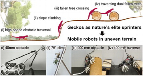
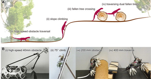
Mobile robots are rapidly expanding in capability and application, yet remain unable to successfully navigate complex real-world terrain [Citation1–3]. Improving robot mobility is essential for applications in agricultural and environmental monitoring, disaster response and a variety of other inspection tasks [Citation4–6]. The past decade has presented a dramatic expansion in the development of mobile robots and the application of robotic systems to practical tasks. Despite the proliferation of computation and sensing at the small scale, robots remain mostly incapable of accessing all but the most evenly structured environments, and cannot reach the performances of natural systems [Citation7,Citation8]. On the other hand, animals in a forest, such as geckos, acrobatically sprint over uneven terrain horizontally, vertically and even over the surface of the water at the same high speed [Citation9] (Figure A). The major reason for this ability of geckos is their long and elastic tails, which enable them to act as nature's elite sprinters. However, many of the biological mechanisms which allow animals to explore the natural world remain poorly understood at the fundamental, biomechanical level. We believe both challenges can be addressed with robophysical models: biorobotic systems that serve as ‘model animals’ for biology research to deepen insights in nature, while also allowing mobile robots to approach biological capabilities for navigation and exploration [Citation10,Citation11].
Figure 1. Target locomotive tasks. (A) A supposed scenario for locomotion in a forest. (B) The environment for robot experiments. In both (A) and (B), (i) high speed obstacle traversal, (ii) slope climbing, (iii) fallen tree crossing, (iv) dual fallen trees traversing.
One of the most distinctive features of animal locomotion compared to contemporary robotics is the application of ‘morphological intelligence’ instead of exhaustive sensing and computation. Often, the immediate response of a natural system to a perturbation is not driven by an action from the animal, but by the mechanical response of a body structure. The most immediate advantage of this lies in robustness; a mechanical response does not rely on sensory information and therefore is less likely to fail due to rapidity of movement or the loss of stimuli (e.g. nocturnal conditions). A response coordinated by the brain also needs additional time to transmit, and is bandwidth limited. These challenges apply equally to robots moving through the environment, and the application of mechanical intelligence is significant for creating resilient, practical robots.
A vital way in which such mechanical intelligence can be realised is through the use of soft actuators and compliant systems, which bring intrinsic compliance and locomotion enhancing structural non-linearities [Citation1,Citation8]. Organic bodies are composed predominantly of water, and can, mainly by deforming, store or release energy in tissues and facilitating dynamic, high strain behaviours which are in stark contrast to the movements of rigid synthetic robots. The use of compliance in climbing systems has already been shown to be vital for vertical climbing with spines [Citation12–16]. Soft materials dissipate energy from impacts extremely effectively [Citation17], damping oscillations, and counteracting discontinuous movements [Citation18] and forces. Soft materials can be utilised in robotics to develop platforms that are adaptable and more life-like in their capabilities [Citation19].
In this paper, we will explore a suite of active and passive adaption mechanisms to allow a robot to climb over irregular terrain, ascend slopes, and traverse obstacles. To achieve the locomotive tasks, we especially utilise neck and tail effects in animal locomotion. This includes their compliance, mass distribution changes, different wheg [Citation20] designs and the use of a tail in both active and passive modes, taking a cue from the use of tails to stabilise climbing in geckos [Citation21]. In the following sections we will present three types of locomotive robots, the results of various performance tests and the insights gained into adaptations for robust locomotion.
2. Locomotion effects from mass distribution changes
During locomotion, many animals are able to use appendage inertia to stabilise and reorient themselves [Citation21,Citation23]. Also in robotics, an actuatable inertial element enables robots to rapidly change their velocity vector [Citation24,Citation25] and orientation of their bodies [Citation26,Citation27]. Where there is a loss of contact, an inertial reaction force is particularly effective [Citation28], as it can produce a more rapid response than a fluid reaction force, for example. Inertial reaction forces are also used to store energy in elastic elements [Citation29], and thereby may dissipate it gradually. Massive tails and elongated necks often occur in nature, and while these appendages serve multiple functions, they may have positive effects on locomotion. A salient example is the role of neck oscillations in reducing giraffe foot forces [Citation30], or the use of tails by kangaroos for stability and efficiency [Citation31,Citation32].
Biorobotics can be used to provide control experiments on the effect of mass distribution on locomotion. A previous study [Citation22] examined the effect of change mass and inertia on the obstacle traversal dynamics of a robot with round wheels and whegs. A meta-analysis of the results in [Citation22] is shown in Figure , in which it can be seen that a forward biased or ‘head’ mass is beneficial in wheeled robots (Figure B). In legged whegs-based locomotion, tail mass was destabilising but head mass was not favourable relative to symmetric mass placement (Figure A).
Figure 2. A meta-analysis of the results in [Citation22], in which asymmetric masses were attached to legged (A) and wheeled (B) robots crossing an obstacle: An experiment with static masses showed that biasing the mass distribution forward and backward had a significant effect on response to an obstacle during terrestrial locomotion. A whegs robot was strongly destabilised by tail mass (C) while rigid and soft wheeled robots were both helped by addition of a static head mass (D).
![Figure 2. A meta-analysis of the results in [Citation22], in which asymmetric masses were attached to legged (A) and wheeled (B) robots crossing an obstacle: An experiment with static masses showed that biasing the mass distribution forward and backward had a significant effect on response to an obstacle during terrestrial locomotion. A whegs robot was strongly destabilised by tail mass (C) while rigid and soft wheeled robots were both helped by addition of a static head mass (D).](/cms/asset/4359e604-947a-42db-80e0-f00c2eecbf36/tadr_a_1887760_f0002_oc.jpg)
Other studies have shown that the elastic decoupling of mass atop a robot traversing an obstacle-laden path can increase speed while reducing energy consumption [Citation33]. We therefore sought to extend our investigation of asymmetric loading with elastically suspended neck masses. To aid design, we began with a multibody simulation of a wheeled robot encountering an obstacle. The model treats the robot as a uniform block measuring 20 x 15 x 5 cm, with a mass of 2 kg, with four 10 cm diameter wheels, each weighing 0.125 kg, for a total mass of 2.5 kg. Only contact forces between the wheels and the ground are modelled. Inertia is calculated based on the assumption of uniform density for all objects. The wheeled robot has a head mass comprising 10% of body weight (0.25 kg), modelled as a point mass at the end of a rigid rod, connected to the body via a torsion spring, such that the neck moves passively in response to body pitching (Figure A). The simulation was developed in the Simscape Multibody package of Matlab/Simulink 2019b, using the contact forces library [Citation34] to model the impact with an obstacleFootnote1.
Figure 3. After showing a noticeable effect with static mass changes [Citation22], we used a simulation to explore the effect of an elastic head (A). A neck and head were modelled as a mass (equal to 10% body mass) on a rigid rod, connected to the body via a torsional spring. (B) The simulation showed that the pitching of the body in response to an obstacle could be suppressed by the appropriate neck size and stiffness, although certain neck lengths and stiffnesses caused the robot to overturn (red shaded regions, indicating runs where the robot did not reach >2 m past the obstacle, or >10 body lengths). (C) RMS pitch rate over the entire run captures both pitch back and pitch forward afterward.
![Figure 3. After showing a noticeable effect with static mass changes [Citation22], we used a simulation to explore the effect of an elastic head (A). A neck and head were modelled as a mass (equal to 10% body mass) on a rigid rod, connected to the body via a torsional spring. (B) The simulation showed that the pitching of the body in response to an obstacle could be suppressed by the appropriate neck size and stiffness, although certain neck lengths and stiffnesses caused the robot to overturn (red shaded regions, indicating runs where the robot did not reach >2 m past the obstacle, or >10 body lengths). (C) RMS pitch rate over the entire run captures both pitch back and pitch forward afterward.](/cms/asset/19069477-a2c5-4ca1-8362-df55696e0e7f/tadr_a_1887760_f0003_oc.jpg)
A range of neck lengths and stiffnesses were simulated, up to a neck length of twice body length, over a stiffness range sufficient to support the neck's weight. The robot response to an obstacle was compared using robot dimensions, speeds and obstacle sizes matched to those found in [Citation22]). We calculated the peak pitch backward angle and RMS (Root Mean Square) body angular velocity, representing the amount of perturbation to the body caused by the obstacle. We used RMS angular velocity to capture both the initial upward deflection of the body and the over-rotation and pitch forward after the obstacle. In some instances, the robot pitched too far and overturned (Figure B,C, shaded areas). Simulations showed that a longer neck reduced body pitching (Figure B), but the most significant reductions in pitching required impractical neck lengths of over 1.5 times body length (a morphology rarely seen in nature). The same large reduction in pitching could be achieved by multiple combinations of neck length and compliance, although some elastic necks acted to increase maximum pitchback.
Some of the change in pitch behaviour comes from the increase in total inertia from the neck length, and some comes from absorption of energy by the neck joint, and an appropriately compliant neck joint could absorb more energy during obstacle traversal, without requiring overly large neck sizes (Figure B–C). This simulation shows that neck length and compliance can have positive effects. However, it only uses a single obstacle size and wheel diameter, and is not exhaustive. It also does not explore the effect of damping or active movement of the neck joint.
To confirm this with physical model data, in this paper we extend the previous investigation with a compliant neck, allowing additional active neck movement and energy absorption during obstacle traversal. We then test mass distribution changes on a smaller climbing platform, to see if beneficial effects for incline running can also be found.
3. Robot design
In this section, we present three small four-wheeled platforms, which are inspired by animals (Table ). The initial prototype has a solid chassis, a compliantly mounted neck [Citation22], and motor actuated four whegs (Figure A). The compliance can be actively changed by an actuator mounted on the chassis. The second prototype has a soft stabilising tail [Citation35], spined whegs, and an adjustable mass distribution (Figure B). Based on observations from tests of their performances traversing obstacles and ascending an incline, we then develop a third robot with improved performance and a soft wheel-leg design, which builds from the lessons learned in the prototypes (Figure C).
Figure 4. (A) Side view of the elastic suspension robot prototype. (B) Top view of the slope climbing robot prototype, showing the drive components and the holder for a centre-biased added mass. (C) View of the active tail robot prototype, showing the novel wheg design and variable sprawl. The inset shows a CAD drawing of the compliant fin ray wheg.
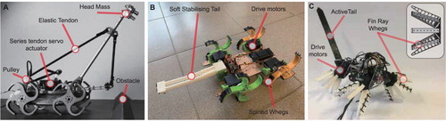
Table 1. Robot specs and features: Additional mass represents distributable mass on a neck or a tail. Body length excludes neck or tail length.
3.1. Elastic suspension prototype
The same platform used in [Citation22] is used here, now extended with an elastic neck and a simple series-elastic actuator (Figure A). The chassis is a custom built, four wheeled robot from TRIC Robotics (Newark, USA), that uses two drive motors to power left and right side wheels i.e. ‘skid steering’. Wheel pairs on each side are linked by a chain and sprockets. Power is provided by three 18650 lithium cells and an ATMega328p (Arduino Nano) is used for motor control.
The elastic neck mass is attached to a 300 mm aluminium pipe which is hinged at its root, to form a rigid pendulum. Pretensioned latex tubing is then attached to the neck to hold it upright but allow pitching motion. One latex tube is connected to a servo motor, allowing tension to be actively adjusted during locomotion.
3.2. Climbing prototype
The second climbing robot is actuated by four servomotors (HSR-2645CR, 53 g mass), each driving a single wheg at a prescribed speed, with a maximum torque of 0.78 N·m per wheg, or a combined maximum forward force of 6.4 kg (ten times body mass), based on the maximum wheg radius of 5 cm (Figure B). The robot chassis is laser cut from fibreboard, while the mounting hardware, whegs and compliant tail are fabricated using a fused deposition 3D printer. The servos are controlled by a radio receiver module, which accepts speed commands from the operator. The compliant tail has an embedded soft capacitive sensor (bendlabs, one axis sensor), from which data is recorded over a Bluetooth serial connection. The main structure of each wheg is printed using PLA plastic, and a separately printed compliant set of spines, made from TPU elastomer is bonded to the traction surface of each wheg to facilitate climbing.
Changes in mass distribution can be used to examine the salient features of locomotion dynamics [Citation22]. As such, receptacles were attached to the robot so that the robot's centre of mass could be moved forward or backward, and the consequences for locomotion were observed. The total robot weight without the added masses is 605 grams, and the mass added was 121 grams, or 20% of the total.
3.3. Active tail prototype
A new robot with a more compliant wheg design and a controllable tail was created to examine the efficacy of the active tail in climbing large obstacles (Figure C). The third iteration of the robot retains the four-wheel-drive layout, but replaces the servomotors with more sophisticated actuators (Dynamixel XL430, 1.5 N·m stall torque) and adds an actuated tail motor and adjustable sprawl. The additional sprawl and tail motor of the robot, as well as a larger battery pack (11.1 V, 3 × 18650 cells) have increased its mass relative to the previous robot by 50%, to 900 grams. However, the torque capacity of the motors has doubled, and so overall performance has increased. The conventional whegs of the previous prototype are replaced with a new soft wheel-leg design which increases the contact area available for climbing, adds additional compliance and allows for gait and posture changes for obstacle traversal via actuation of the wheel sprawl angle. The robot chassis is laser cut from 2 mm plastic sheets, and can be controlled using Python scripts either from the onboard single-board computer (Raspberry Pi A+), or with commands sent directly to the robot over USB.
The new wheel legs are formed from eight soft Fin Ray effect spokes made from TPU elastomer with spines [Citation36], attached to a rigid hub (Figure C, inset). The Fin Ray
effect allows the spokes to conform to surfaces and grip convex shapes using the sprawl motors. Four sets of three spines each are distributed along a spoke, such that the spoke's compliance allows each spine set to move independently and better engage with the climbing substrate.
Finally, the robot is equipped with a tail, fabricated from laser-cut plastic sheets. To examine the effect of different tail compliances, four tails were manufactured with different flexural stiffness, ranging from a 3 mm thick rigid PVC tail to a very soft tail formed from a 2 mm thick sheet of synthetic rubber (SBR). All tails used have the same width and length, the latter being equal to 90 body length, for a total robot length of 580 mm (similar to many arboreal lizards in which tail length and body length are approximately equal).
4. Experimental setup
We created locomotive tasks similar to possible scenarios that a small animal, like a gecko, encounters in nature, such as in a forest (Figure A): The robot rapidly traverses an obstacle, ascends a steep slope and climbs over a fallen tree then traverses between fallen trees. For each task, we build an experimental setup compromising of artificial obstacles and then test the robots' performance.
The robot's progression was recorded with a high-speed camera (AOS S-MOTION) and a markerless pose estimation algorithm was then run on the resulting videos, using the open-source DeepLabCut library [Citation37], with a set of 60 images marked manually and used to train a neural network. The resulting tracking information was post-processed in Matlab, and speeds, body angles and sensor data were analysed to assess locomotive performance.
4.1. High-speed obstacle traversal
The robot was made to traverse a triangular obstacle at a constant approach speed. to provide traction the trackway was covered with rubber and the obstacle was covered by sandpaper. The robot was driven at a fixed motor power level, with positions and orientations of the neck and body recorded using a single high-speed camera (AOS S-Motion) at 500 Hz. Repeated obstacle traversals were carried out, using different neck stiffnesses, and also testing forward actuation of the neck at the moment of contact with the obstacle. As a control, the robot was also tested with the elastic neck removed entirely.
4.2. Slope climbing
A wooden slope was covered in a 1 cm steel mesh grid and placed at a variety of fixed angles, of up to 80 degrees to the horizontal, to test the robot's climbing performance, and the efficacy of mass distribution changes, as well as the addition of a contact tail. To test robustness, an obstacle could be placed in the robot's path (Figure B (ii)).
4.3. Fallen tree crossing
In this test, an obstacle height was set equal to the robot's body length (excluding tail, Figure B (iii)). The obstacle was formed from a steel cylinder covered in a 5 mm layer of natural cork for traction. The experiments were conducted with the active tail prototype robot. The robot was driven forward at a fixed speed, with the rotation of each Fin Ray wheg held constant. The tail actuation was then varied, including holding the tail fixed, removing the tail completely, swinging the tail downward at different points of time, and gradually adjusting the tail angle as the robot climbed. These tests were performed for tails of varying stiffness. In these experiments, position tracking method is different from others. Visual markers were placed on the robot, pose information was extracted using video analysis software (OpenPhysics Tracker) and data were post-processed in MATLAB.
Table 2. Obstacle Traversal Success with varying tail stiffness.
4.4. Dual fallen trees traversing
After examining the performance of the robot crossing a single large obstacle, we examined its behaviour traversing two smaller obstacles in quick succession (Figure B (iv)), modelling a typical scenario for a small robot moving in unstructured terrain. In this instance, we used two wooden blocks with a height equal to the robot's wheel height, and varied their separation up to two body lengths (excluding tail), which corresponds to a distance just below the total robot length (including tail). Separation with spacing greater than two body lengths is not considered as this would allow the obstacles to be traversed in succession similar to completely separate obstacles, which the robot is demonstrably capable of doing. This test was then repeated with the active tail prototype robot.
5. Results
5.1. High-speed obstacle traversal
Elastically mounted mass distribution suppresses impact force
The elastic neck prototype was run over an obstacle repeatedly with various head configurations (Figure A–D). We analysed body and neck angles over time using videography data. For performance metrics, we considered the maximum pitchback angle during obstacle transit and the root mean squared body angular velocity over the entire run, the latter serving as a measure of the energy of the perturbation. Finally, we considered the time taken for the robot to transit a distance of two body lengths, centred on the obstacle, to quantify how much the obstacle impeded the robot.
Figure 5. Traversing an obstacle with an elastically suspended neck mass. We tested four different configurations: (A) An elastic neck with low stiffness, (B) an elastic neck actuated forward at the moment of obstacle contact, (c) an elastic neck with high stiffness and (C) no neck. The robot was then run over an obstacle, and the response recorded. We found that the actively moved neck showed the lowest pitch back (D), and that the presence of the neck in all configurations reduced the total perturbation (E). This allowed the robot to cross the obstacle more quickly (F).
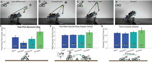
It was immediately clear from the data that the elastic head served to suppress the perturbation from the impact with the obstacle (Figure E–F), and allowed the robot to move more quickly along the track (Figure G). The effect was the same at all neck tension levels, although actuating the neck forward at the moment of impact reduced the maximum pitchback slightly (Figure E). Actuating the neck forward added ‘pitch-down’ angular velocity to the system, which served to reduce the maximum pitch back angle when a ‘pitch-up’ angular velocity was imparted by the obstacle.
These results indicate that an elongated, elastic has some locomotion benefit, as indicated by the initial simulation (Figure ). However, the inertial damping effect alone may not be sufficient to make the morphology evolutionarily favourable, and an elongated head carries penalties in maneuverability and overall body mass. However, an extended neck also provides advantages to perception and access to nutrition, which combined with a benefit to locomotion may be enough to produce changes in body plan.
5.2. Slope climbing
Tail engagement enables robot to climb steep slopes
First, climbing experiments were run with the robot tail removed. Without the tail to ensure forefoot contact, the robot was unable to climb at an angle greater than 45. With tail attached and positioned in contact with the surface such that the tail was flexed and a small preload to the robot was applied, this angle increased to 70
(Figure A) and transitions from the horizontal to inclines of up to 75
were possible (Figure E).
Figure 6. Climbing experiment results. (A) Example trajectories extracted from video data using DeepLabCut [Citation37]. (B) Soft tail sensor is able to sense pitch-back in the robot. In this case, the pitch-back leads to a catastrophic fall, but future robots could employ an active tail reflex to prevent loss of contact, the inset to the right shows an image the soft sensor. (C) Mean amplitude of pitch oscillations of the robot body at 45. The use of a tail significantly suppresses oscillation, and prevents loss of traction. (D) Tail increases speed due to the reduced oscillation, which means less foot slippage. Changing weight distribution also has an effect on the oscillations and reduced pitching results in a faster climb speed due to improved traction. (E) At 70
the robot is unable to climb without a tail. The addition of 20% additional mass at different locations has little impact on oscillations because the robot must climb at a lower speed, and so motion is steadier. (F) Again, speed and oscillation are consistent with each other.
![Figure 6. Climbing experiment results. (A) Example trajectories extracted from video data using DeepLabCut [Citation37]. (B) Soft tail sensor is able to sense pitch-back in the robot. In this case, the pitch-back leads to a catastrophic fall, but future robots could employ an active tail reflex to prevent loss of contact, the inset to the right shows an image the soft sensor. (C) Mean amplitude of pitch oscillations of the robot body at 45∘. The use of a tail significantly suppresses oscillation, and prevents loss of traction. (D) Tail increases speed due to the reduced oscillation, which means less foot slippage. Changing weight distribution also has an effect on the oscillations and reduced pitching results in a faster climb speed due to improved traction. (E) At 70∘ the robot is unable to climb without a tail. The addition of 20% additional mass at different locations has little impact on oscillations because the robot must climb at a lower speed, and so motion is steadier. (F) Again, speed and oscillation are consistent with each other.](/cms/asset/32bc714f-f3af-4153-ac71-a3187602436b/tadr_a_1887760_f0006_oc.jpg)
Figure 7. (A) Side view of a climbing gecko, showing the use of the tail to recover from a forefoot slip [Citation21]. (B)–(D) Image sequences showing the robot traversing a 30 mm obstacle. (B) 45 ramp angle, 4 successful trials. (C) 50
ramp angle, 2 successful trials out of 4. (D) 60
ramp angle, 2 successful trials out of 4. (E) 75
ramp angle which the robot successfully climbed.
![Figure 7. (A) Side view of a climbing gecko, showing the use of the tail to recover from a forefoot slip [Citation21]. (B)–(D) Image sequences showing the robot traversing a 30 mm obstacle. (B) 45∘ ramp angle, 4 successful trials. (C) 50∘ ramp angle, 2 successful trials out of 4. (D) 60∘ ramp angle, 2 successful trials out of 4. (E) 75∘ ramp angle which the robot successfully climbed.](/cms/asset/fed5094b-3b5c-4aa4-9431-b9495ee558b9/tadr_a_1887760_f0007_oc.jpg)
This shows that a passive tail is important for reliable climbing, as has been observed in previous robots [Citation35]. However, fast climbing arboreal geckos employ an active tail reflex to dynamically respond to the loss of contact with the climbing surface (Figure A) [Citation21]. The soft sensor integrated into the robot's tail provides a pathway for this response. In Figure B we see a time history of the robot ascending a 70 incline in which the forward wheels lose traction, and the torque from the rear wheels causes the robot to pitch-back, lose contact and fall. The sensor in the tail responds rapidly to this perturbation, and in a future iteration of the robot, this could be used as a control signal to catch falls dynamically as the robot climbs.
The reason for the high failure rate without a tail is illustrated in Figure C, in which the mean deviation in body angle over an ascent is plotted. Without the tail attached, the size of the body pitch oscillations increases significantly, which results in a higher likelihood that enough of the spines become detached from the climbing surface and cause a catastrophic fall. The reduction in oscillation also means less foot slip, and therefore a faster climb rate is achieved through the use of the tail at 45 degrees (Figure D).
Mass distribution controls body pitch back
Experiments with the tail attached were run at 70, and masses attached to the robot at different positions. The mass added weighed 121 grams, or 20% of total robot mass, and was placed either at the centre of the robot's wheelbase, or one wheelbase length forward of the centre, such that the mass was in front of the wheels.
During climbing, the mean ascent rate is strongly impacted by loss of traction for brief periods, during which the robot makes no forward progress. Loss of traction typically occurs in the front wheels, as the rear motor torque acts to raise the nose of the robot if unresisted. The tail counters this torque, but it was expected that further improvement could be made by adding forward-biased mass, which has the dual effect of countering pitch-back torque and increasing the robot's moment of inertia. During shallow angle climbing experiments the added mass did have the effect of reducing oscillations (Figure C), but at steeper angles, no consistent difference was observed between different loading cases (Figure E), likely due to the slower climb speed due to the steeper angle (Figure D, F).
Compliant wheg leg makes obstacle traversal easier
Relative to climbing robot designs that employ more careful, quasi-static foot placement, the use of whegs in climbing incurs a penalty with respect to body oscillations and increases the distance of the robot's centre of mass from the wall. On the other hand, the use of whegs allows the robot to traverse obstacles more easily, which is an essential feature of any robot operating in an outdoor environment. We show the fabricated robot to be able to cross obstacles while ascending an incline of up to 60 degrees from the horizontal plane. Several different ramp angles were tested, and it was found that the robot could consistently cross obstacles at 45 degrees (Figure B), but had reduced success at steeper angles (Figure C–D). The typical failure reason in an obstacle traversal was the loss of traction in the rear whegs, before the front whegs had traversed the obstacle.
5.3. Fallen tree crossing
Active tail controls body pitch angle
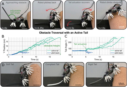
We found that the robot was not able to climb the obstacle without the use of the tail, and would pitch back in attempting to do so. Nor was it able to traverse the obstacle with the tail held fixed in place at any angle relative to the robot body, independent of the stiffness of the tail (Table ). However, the robot was able to cross the obstacle when the tail was actuated and swung downward at specific points to push against the ground as the robot climbed (Figure A–C). The moment at which the tail was actuated was critical, as an early application of the tail force meant the robot could not transition from its horizontal position onto the obstacle, the tail hindering it from angling its body upward. A late actuation of the tail would cause the robot to lose contact with the obstacle and pitch backward, yet initially positioning the tail upward at an angle of 130 meant the robot would only tip over marginally before being caught by the tail, which could then actively push it back into position. Activating the tail right at the moment of pitch-back proved most effective (Figure C). Manually applying constant tail pressure and increasing the downward angle of the tail incrementally, helped the robot to climb the obstacle, suggesting that a force control approach could be beneficial. The addition of some compliance to the tail doesn't impede climbing the obstacle, and may help by making the robot less sensitive to the timing of tail actuation. However, too much compliance and the tail is unable to transmit enough force to enable the robot to climb (Figure D).
Figure 8. The climbing robot traversing a large obstacle (obstacle height = body length). (A) Image sequence of a successful traversal with a tail of medium stiffness, showing the robot (from left to right) approaching the obstacle, pitching backward as it ascends, actuating its tail to prevent loss of contact, and having ascended the obstacle. (B) Time history of several obstacle ascent trials, showing failed ascents with the tail remaining unused at 130 and successful ascents using the active tail. (C) Tail angle time histories of the same set of traversal tests. Change of tail angle during pitch-back is due to the robot's weight bending the tail back. (D) Robot failing to scale obstacle with a soft tail, climbing obstacle with a compliant tail and using a rigid tail to actively aid the ascent.
5.4. Dual fallen trees traversing
Flexible tail brings adaptability for environmental structure
As with the first obstacle, we investigated the effect of a change in tail stiffness, using the same set of four tails (Table ). The results of several tests with a passive tail are shown in Table . The cases in which the separation of the two obstacles is less than body length are trivial, and the robot crosses successfully as it would crossing a single large obstacle. However, with a passive, rigid tail the robot is unable to traverse the second obstacle as the tail prevents the robot from pitching to climb (Figure A). Instead, transitioning between the obstacles is best achieved with a compliant tail (Figure B), which can flex and allow the robot to conform to the obstacle (Table ).
Figure 9. Dual obstacle traversal fails with a rigid tail (A) but is successful with a soft tail (B).
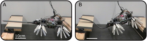
Table 3. Dual Obstacle Traversal Success.
The robot is not capable of entirely crossing an obstacle with the compliant or soft tail, these being unable to transmit the necessary force, yet scaling the obstacle with its front whegs is possible using those tail configurations. As not even this is achievable for failed attempts with other tail configurations, the robot being able to transition the gap and scale the second obstacle with the front whegs was regarded as a successful attempt. In future iterations of the robot, adjustable tail stiffness could give both the advantage of transitioning between obstacles with a soft tail, as well as then fully traversing the obstacle aided by a stiffer tail.
6. Discussion
An active tail response is necessary for the most challenging manoeuvres, as shown by the climbing of the large obstacle. However, passive tail responses are intrinsically more robust, as response speed and reliability are not impeded by computation or the availability of sensing. We found that a soft tail improved inter-obstacle navigation, but also prevented the ascent of a single large obstacle. In nature, animals are able to dynamically adjust the stiffness of their appendages through their muscles. In a future iteration of this robot, we expect that a soft tail with adjustable stiffness [Citation38] will provide the broadest benefit to locomotion robustness, as well as additional advantages in climbing, such as conforming to uneven surfaces for traction enhancement.
In this paper, we have explored adaptations for mobile robots dealing with irregular and uneven terrain. The latest robot iteration shows promise, and future work will explore the use of feedback-controlled tails using onboard sensors [Citation39] (Section 5.2) to reject a variety of perturbations and control terrain transitions, going beyond the simple cases examined in this paper. The adjustable sprawl capability has not been explored in detail yet, and future work will examine how this feature can be used to adjust posture, conform to irregular surfaces, and apply active grip to retain traction. The improved controllability of the new robot will also facilitate control of relative phase between the different wheel legs and allow investigation of the effect on obstacle traversal, body oscillation and overall performance.
7. Conclusion
Utilising ‘morphological intelligence’, we developed three types of biologically-inspired robots, with elastic capabilities and examined their locomotive performance with various types of obstacles. The results showed optimised elasticity and mass distribution bring robustness of rapid locomotion in uneven terrain. The results address the question of utilising leg and tail compliance in scenarios of obstacle traversal in uneven terrain and suggest that modifying the stiffness [Citation39–41] continuously in response to disturbances could be advantageous for enhancing locomotion performance as well as robustness. The emerging field of biorobotics facilitates investigation of locomotion as advances in experimental robotics provide novel instruments that exhibit great promise for testing scientific hypotheses [Citation11]. Biorobotics advances our understanding of the design principles for soft robots by emulating the control principles of perturbation rejection in biological systems, and allow us to transfer them to robotic designs.
Supplemental Material
Download MP4 Video (18.6 MB)Acknowledgements
We thank the Max Planck Society and the Cyber Valley Initiative for grants to Ardian Jusufi (CyVy-RF-2018-09). Also appreciated is the Alexander von Humboldt Society's postdoctoral financial support of Robert Siddall. We thank the Central Service Station for Robotics and Mechatronics at the Max Planck Institute for Intelligent Systems (MPI-IS) for their continuous assistance. The authors would like to acknowledge the Fabrication Laboratory Bonevet managing director Arber Lleshi as well as overall director Vllaznim Xhiha. We thank Fabian Schwab of the Lab for Locomotion in Biorobotic and Somatic Systems for valuable insights.
Disclosure statement
No potential conflict of interest was reported by the author(s).
Correction Statement
This article has been republished with minor changes. These changes do not impact the academic content of the article.
Additional information
Funding
Notes on contributors
Robert Siddall
Rob Siddall is on a Postdoctoral Humboldt Fellowship at the Locomotion Biorobotic & Somatic Systems group at the Max Planck Institute for Intelligent Systems, subsequently a lecturer in robotics at the University of Surrey. He received his Master's degree in Aerospace Engineering from the University of Cambridge and his PhD in Aeronautics from Imperial College London. He is interested in multimodal locomotion, with an emphasis on hybrid forms of flight.
Toshihiko Fukushima
Toshihiko Fukushima is a research engineer in the lab for Locomotion in Biorobotic & Somatic Systems at the Max Planck Institute for Intelligent Systems. He received his Bacholar's degree in Engineering and Master's degree in Interdisciplinary Information Studies from Toyota Technological Institute in 2012 and from The University of Tokyo in 2014 respectively. After that, he has worked as an automotive engineer at Toyota Motor Corporation, Toyota Motorsport GmbH and NTN Wälzlager (Europa) GmbH. His current fields of interest are bio-inspired robotics, dynamic locomotion and soft robotics.
Drilon Bardhi
Drilon Bardhi is currently a student of the Faculty of Medicine, branch of general medicine and integrated studies at the University of Prishtina ‘Hasan Prishtina’. His interests include the use of robotic systems for minimally invasive interventions, the development of new prostheses, and life support systems.
Buna Perteshoni
Buna Perteshoni is currently a student at Des Moines Area Community College, in the Tech and Industry department. Her interests are focused on 3D design of high precision dies and creating a sustainable plant with a economic impact in her country.
Albulena Morina
Albulena Morina is currently a student of the Faculty of Mathematics and Natural Sciences, branch of physics at the University of Prishtina ‘Hasan Prishtina’. Her interests include the use of robots with repetitive movements in biological laboratories, and the physics behind robotics locomotion.
Era Hasimja
Era Hasimja is a student of University of Business and Technology, branch of computer science and engineering at the UBT - Prishtine. Her interests include the use of computers to solve real-world problems, especially focused on controlling robots performance by developing complex and flexible models of them.
Yll Dujaka
Yll Dujaka is a student at the Faculty of Electronic and Computer Engineering, branch of electronic engineering at the University of Prishtina ‘Hasan Prishtina’. His interest includes the use of technology in simplifying everyday problems by configuring robot designs.
Gezim Haziri
Gezim Haziri is a student at the Faculty of Electronic and Computer Engineering, branch of Electronic Engineering at the University of Prishtina ‘Hasan Prishtina’. His interest includes making fun and practicable projects that make everyday life tasks easier and designing electronic PCBs.
Lina Martin
Lina Martin received her B.Sc. in Biomimetics from the Westphalian University of Applied Sciences in 2020 and worked as a researcher assistant at the Locomotion Biorobotic & Somatic Systems group at the Max Planck Institute for Intelligent Systems. She is interested in practical biological field research.
Hritwick Banerjee
Hritwick Banerjee is working as a Jr. Scientist in the Locomotion in Biorobotic & Somatic Systems Group at the Max Planck Institute for Intelligent Systems (MPI-IS). In the past, he was working as a Sr. Research Engineer at the Dept. of Biomedical Engineering, National University of Singapore (NUS) (2016–19). Before this, he also worked as a Research Engineer at the NUS (2015–16), Indian Institute of Science (IISc), Bangalore, India (2014–15). He graduated with a Master's Degree in Electrical Engineering from the Indian Institute of Technology (IIT), Gandhinagar (2014) in collaboration with the IIT Kharagpur and the University of Oxford (Institute of Biomedical Engineering), UK.
Ardian Jusufi
Ardian Jusufi is a Max Planck Independent Group Leader, and head of the lab for Locomotion in Biorobotic and Somatic Systems (at the Max Planck Institute for Intelligent Systems), which is also a Cyber Valley research group. Dr. Jusufi is also Associate Faculty at the ETH Center for Learning Systems (CLS). Ardian's formal undergraduate and graduate university training was concluded at the University of California at Berkeley USA. He earned his PhD at the U.C. Berkeley CiBER Center. He was a Postdoctoral Researcher Associate at Queens' and Darwin Colleges, at the University of Cambridge. Ardian was a postdoctoral researcher at Harvard University, under supervision of Prof. Robert Wood of the Harvard Microrobotics Lab at the School of Engineering and Applied Sciences at Harvard University, and the Wyss Institute for Biologically-Inspired Engineering. Ardian was a Lectuer at the Center for Autonomous Systems, Facultuy of Engineering and Information Technology at Sydney University of Technology.
Notes
1 The Simulink model is available for download at https://github.com/robjds/ElasticHead
References
- Trimmer B. Soft robots. Curr Biol. 2013;23(15):R639–R641.
- Iida F, Laschi C. Soft robotics: challenges and perspectives. Procedia Comput Sci. 2011;7:99–102.
- Yang GZ, Bellingham J, Dupont PE, et al. The grand challenges of science robotics. Sci Robot. 2018;3(14):eaar7650.
- Gilbertson MD, McDonald G, Korinek G, et al. Serially actuated locomotion for soft robots in tube-like environments. IEEE Robot Automat Lett. 2017;2(2):1140–1147.
- Cheney N, Bongard J, Lipson H. Evolving soft robots in tight spaces. Proceedings of the annual conference on genetic and evolutionary computation; ACM; 2015. p. 935–942.
- Banerjee H, Pusalkar N, Ren H. Single-motor controlled tendon-driven peristaltic soft origami robot. J Mech Robot. 2018;10(6):064501.
- Lipson H. Challenges and opportunities for design, simulation, and fabrication of soft robots. Soft Robotics. 2014;1(1):21–27.
- Rus D, Tolley MT. Design, fabrication and control of soft robots. Nature. 2015;521(7553):467–475.
- Nirody JA, Jinn J, Libby T, et al. Geckos race across the water's surface using multiple mechanisms. Curr Biol. 2018;28(24):4046–4051.e2.
- Jusufi A, Kawano DT, Libby T, et al. Righting and turning in mid-air using appendage inertia: reptile tails, analytical models and bio-inspired robots. Bioinspir Biomim. 2010;5(4):045001.
- Libby T, Moore TY, Chang-Siu E, et al. Tail-assisted pitch control in lizards, robots and dinosaurs. Nature. 2012;481(7380):181–184.
- Kim S, Asbeck AT, Cutkosky MR, et al. Spinybotii: climbing hard walls with compliant microspines. Proceedings of 12th international conference on advanced robotics (ICAR); IEEE; 2005. p. 601–606.
- Asbeck AT, Kim S, McClung A, et al. Climbing walls with microspines. Proceedings of the IEEE international conference robotics and automation (ICRA); IEEE; 2006.
- Martone M, Pavlov C, Zeloof A, et al. Enhancing the vertical mobility of a robot hexapod using microspines. 2019. arXiv:190604811.
- Manoonpong P, Petersen D, Kovalev A, et al. Enhanced locomotion efficiency of a bio-inspired walking robot using contact surfaces with frictional anisotropy. Sci Rep. 2016;6:1145.
- Liu Y, Sun S, Wu X, et al. A wheeled wall-climbing robot with bio-inspired spine mechanisms. J Bionic Eng. 2015;12(1):17–28.
- Roderick WR, Cutkosky MR, Lentink D. Touchdown to take-off: at the interface of flight and surface locomotion. Interface Focus. 2017;7(1):20160094.
- Nguyen HN, Siddall R, Stephens B, et al. A passively adaptive microspine grapple for robust, controllable perching. Proceedings of 2nd IEEE international conference on soft robotics (RoboSoft); IEEE; 2019. p. 80–87.
- Souri H, Banerjee H, Jusufi A, et al. Wearable and stretchable strain sensors: materials, sensing mechanisms, and applications. Adv Intell Syst. 2020;2:2000039.
- Boxerbaum AS, Oro J, Peterson G, et al. The latest generation whegsTMrobot features a passive-compliant body joint. Proceedings of IEEE/RSJ international conference on intelligent robots and systems (IROS); IEEE; 2008. p. 1636–1641.
- Jusufi A, Goldman DI, Revzen S, et al. Active tails enhance arboreal acrobatics in geckos. Proc Natl Acad Sci. 2008;105(11):4215–4219.
- Siddall R, Schwab F, Michel J, et al. Heads or tails? cranio-caudal mass distribution for robust locomotion with biorobotic appendages composed of 3d-printed soft materials. Proceedings of conference on biomimetic and biohybrid systems; Springer; 2019. p. 240–253.
- Wilson AM, Lowe J, Roskilly K, et al. Locomotion dynamics of hunting in wild cheetahs. Nature. 2013;498(7453):185–189.
- Patel A, Braae M. Rapid turning at high-speed: Inspirations from the cheetah's tail. 2013 IEEE/RSJ international conference on intelligent robots and systems (IROS); IEEE; 2013. p. 5506–5511.
- Patel A, Braae M. An actuated tail increases rapid acceleration manoeuvres in quadruped robots. Innovations and advances in computing, informatics, systems sciences, networking and engineering; Springer; 2015. p. 69–76.
- Johnson AM, Libby T, Chang-Siu E, et al. Tail assisted dynamic self righting. Adaptive mobile robotics. World Scientific; 2012. p. 611–620.
- Libby T, Johnson AM, Chang-Siu E, et al. Comparative design, scaling, and control of appendages for inertial reorientation. IEEE Trans Robot. 2016;32(6):1380–1398.
- Kohut N, Haldane D, Zarrouk D, et al. Effect of inertial tail on yaw rate of 45 gram legged robot. International conference on climbing and walking robots and the support technologies for mobile machines; 2012. p. 157–164.
- Fukushima T, Nishikawa S, Kuniyoshi Y. Active bending motion of pole vault robot to improve reachable height. 2014 IEEE international conference on robotics and automation (ICRA); IEEE; 2014. p. 4208–4214.
- Basu C, Wilson AM, Hutchinson JR. The locomotor kinematics and ground reaction forces of walking giraffes. J Experi Biol. 2019;222(2):jeb159277.
- Dawson TJ, Taylor CR. Energetic cost of locomotion in kangaroos. Nature. 1973;246(5431):313.
- Kram R, Dawson TJ. Energetics and biomechanics of locomotion by red kangaroos (macropus rufus). Comparative Biochem Physiol Part B: Biochem Mol Biol. 1998;120(1):41–49.
- Ackerman J, Seipel J. Energy efficiency of legged robot locomotion with elastically suspended loads. IEEE Trans Robot. 2013;29(2):321–330.
- Steve M. Simscape multibody contact forces library. 2020. retrieved September 27, 2019. Available From: https://github.com/mathworks/Simscape-Multibody-Contact-Forces-Library/releases/tag/20.1.5.1.
- Spenko MJ, Haynes GC, Saunders J, et al. Biologically inspired climbing with a hexapedal robot. J Field Robot. 2008;25(4-5):223–242.
- Spagna JC, Goldman DI, Lin PC, et al. Distributed mechanical feedback in arthropods and robots simplifies control of rapid running on challenging terrain. Bioinspir Biomim. 2007;2(1):9.
- Mathis A, Mamidanna P, Cury KM, et al. Deeplabcut: markerless pose estimation of user-defined body parts with deep learning. Nat Neurosci. 2018;21(9):1281–1289.
- Wolf Z, Jusufi A, Vogt D, et al. Fish-like aquatic propulsion studied using a pneumatically-actuated soft-robotic model. Bioinspir Biomim. 2020;15(4):046008
- Wright B, Vogt DM, Wood RJ, et al. Soft sensors for curvature estimation under water in a soft robotic fish. Proceedings of 2nd IEEE international conference on soft robotics (RoboSoft); 2019. p. 367–371.
- Jusufi A, Vogt DM, Wood RJ, et al. Undulatory swimming performance and body stiffness modulation in a soft robotic fish-inspired physical model. Soft Robot. 2017;4(3):202–210.
- Lin Y, Siddall R, Schwab F, et al. Modeling and control of a soft robotic fishtail with integrated soft sensing. Adv Intell Syst. 2021. In press. doi:10.1002/aisy.202000244
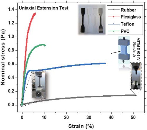
Appendix 1. Tensile tests of tail materials
In order to have precise data on the mechanical properties of the materials used for the various tails, samples were tested in an Instron machine (Instron 5942), following the ASTM D638 IV standard. A calibrated load cell of 500 N was used and samples were loaded and uniaxial strain applied with a ramp rate of 5 mm/min. A results summary is shown in Figure .
Figure A1. Tensile tests of the materials used for the tails of varying compliance, performed with an Instron using ASTM D 638 IV standard samples.