
 ?Mathematical formulae have been encoded as MathML and are displayed in this HTML version using MathJax in order to improve their display. Uncheck the box to turn MathJax off. This feature requires Javascript. Click on a formula to zoom.
Abstract
Quality assurance (QA) guidelines are essential to provide uniform execution of clinical hyperthermia treatments and trials. This document outlines the clinical and technical consequences of the specific properties of interstitial heat delivery and specifies recommendations for hyperthermia administration with interstitial techniques. Interstitial hyperthermia aims at tumor temperatures in the 40–44 °C range as an adjunct to radiation or chemotherapy. The clinical part of this document imparts specific clinical experience of interstitial heat delivery to various tumor sites as well as recommended interstitial hyperthermia workflow and procedures. The second part describes technical requirements for quality assurance of current interstitial heating equipment including electromagnetic (radiative and capacitive) and ultrasound heating techniques. Detailed instructions are provided on characterization and documentation of the performance of interstitial hyperthermia applicators to achieve reproducible hyperthermia treatments of uniform high quality. Output power and consequent temperature rise are the key parameters for characterization of applicator performance in these QA guidelines. These characteristics determine the specific maximum tumor size and depth that can be heated adequately. The guidelines were developed by the ESHO Technical Committee with participation of senior STM members and members of the Atzelsberg Circle.
Introduction
These quality assurance (QA) guidelines for the application of interstitial hyperthermia, as presented here, were developed upon request of the Atzelsberg Circle for Clinical Hyperthermia, which is the Interdisciplinary Working Group of Hyperthermia ‘Interdisziplinäre Arbeitsgruppe Hyperthermie’ (IAH) [Citation1] of the German Cancer Society (‘Deutsche Krebsgesellschaft’) to the European Society for Hyperthermic Oncology (ESHO) [Citation2]. ESHO delegated this task to the ESHO technical committee (ESHO-TC), who formulated the guidelines with participation of experienced members of the Society for Thermal Medicine (STM) [Citation3].
Goal: these guidelines aim to establish a single uniform level of quality assurance and control in hyperthermia treatments delivered in all multi-institutional studies initiated by the Atzelsberg Circle or under the auspices of the ESHO. The goal of this effort is to establish QA guidelines for the application of interstitial hyperthermia (IHT), similar to the QA guidelines for the administration of deep and superficial hyperthermia defined earlier [Citation4–7] and as follow-up to the earlier QA guidelines for interstitial hyperthermia provided by Radiation Therapy Oncology Group [Citation8], earlier reviews on interstitial technology [Citation9,Citation10] and the hyperthermia guidelines by ESHO [Citation11]. The technical properties and clinical practice described in these earlier documents serve as starting point for these updated and expanded guidelines. New in the guidelines is more attention to the consequences of the heterogeneous temperature distributions and high-temperature gradients during clinical interstitial hyperthermia. Furthermore, detailed descriptions are included of standardized QA and working procedures before, during and after clinical application, all based on modern computer technology. Results from these earlier documents are discussed when necessary for understanding the rationale of these new guidelines.
The guidelines serve as the current standard to facilitate that the application and registration of interstitial hyperthermia treatments within clinical trials follow current knowledge and experience both from technological and clinical considerations. Consequently, participation in clinical trials requires both implementation of these QA guidelines and strict adherence to the specific requirements of the clinical study protocol in order to apply hyperthermia to the defined clinical target. Storing treatment data should preferably follow a joint standard format [Citation12]. It is the responsibility of every institute to characterize its hyperthermia equipment and to make the data available to the ESHO-TC. As a follow-up to the development of these QA guidelines and use of the experimental and clinical information obtained via the implementation of the QA guidelines, the ESHO-TC may formulate a list of device types with a description of the potential tumor size and location that can be heated.
The QA-IHT guidelines in this paper are intended for interstitial devices used to generate hyperthermic temperatures within a tumor volume that are predominantly within the 40–44 °C range for 30–60 min typical duration, as an adjunct to radiation therapy [Citation13], chemotherapy [Citation14], and potentially immunotherapy [Citation15]. Hyperthermia delivered in this fashion is targeted toward direct cytotoxicity of nutrient deprived and hypoxic cells, and indirect cell kill by radiosensitization and chemosensitization [Citation16]. Although not covered in this document, similar devices can be used to deliver thermal ablation therapy, where temperatures exceeding ∼50–55 °C and a lethal thermal dose (>240 CEM43 °C) are targeted throughout the tumor and surrounding margin for producing irreversible tissue destruction. The choice between applying ablation or hyperthermia treatment is guided by tumor site-specific considerations and clinical practice.
In particular, these QA-IHT guidelines summarize the characteristics of interstitial heating and cover both technical and clinical aspects of applying IHT and procedures to characterize the heating capabilities of IHT devices. When the QA-IHT guidelines states ‘must’, strict application is required whereas when it states ‘should’, implementation is strongly recommended.
Part I. General definitions
I-A definition of IHT
Interstitial hyperthermia is a heating method using arrays of needle-shaped applicators implanted directly or applicators inserted within catheters that are implanted into the target volume. Commonly treated tumor sites include brain, breast, head and neck, cervix, prostate and bladder. Interstitial applicators have a typical active length of 4–10 cm and a diameter of 1–2 mm. Due to steep radial fall-off of energy and blood perfusion, heating penetration is limited for most modalities to 5–10 mm radius of tumor tissue around each applicator, often dictating that multiple applicators be used.
Interstitial heating techniques are based on the same heating principles as intracavitary and intraluminal techniques, but energy is delivered from interstitial needles or catheters implanted percutaneously into the tumor rather than placed within natural body cavities like cervix, bladder, esophagus and urethra. Benign prostatic hyperplasia may be treated with intraluminal transurethral microwave thermotherapy in the 45–60 °C range [Citation17]. Intracavitary and intraluminal applicators may have active lengths similar to interstitial applicators but are generally not used in multiapplicator arrays and the diameter can be larger, up to 30 mm, depending on size of the cavity involved. These QA guidelines are intended for interstitial hyperthermia, although parts may be applicable to intraluminal and intracavitary hyperthermia which may be considered a special case of interstitial heating using only one applicator.
Although many considerations for QA-IHT are directly comparable to QA considerations for other hyperthermia treatment approaches, there are two major differences which hamper direct transfer of knowledge/experience from external heating technologies. For external hyperthermia, the heating and radiotherapy delivery devices are used independent of each other. In contrast, the clinical use of IHT systems is usually closely interlaced with brachytherapy as both treatments use the same catheters. Hence, power deposition in IHT is confined to the tumor region avoiding the risk of treatment limiting hot spots in surrounding normal tissues, which should lead to better tumor coverage. The comparatively thin rim of heated tissue margin around the heated tumor volume creates a risk of heterogeneous and lower temperatures in the tumor periphery due to the cooling effect of incoming normothermic blood. Due to the steep thermal gradient associated with highly localized IHT heating, achieving acceptable tumor temperature uniformity is possible only with careful placement and spacing of the IHT applicators and with adequate temperature control to achieve a sufficiently high temperature between the applicators without overheating the tissue close to the applicator. Maintaining appropriate insertion lengths and parallel spacing between catheters, sufficient implant catheters in the periphery, along with adequate catheters for thermometry, are critical points of which the radiation oncologist and surgeon must be aware during catheter implantation.
I-B definition of a minimum thermal dose requirement for an interstitial hyperthermia treatment
A fundamental premise of these QA guidelines is that the proven effectiveness of hyperthermia in clinical studies relies exclusively on its thermal effect on tumors, which is dependent on temperature and time [Citation16,Citation18–21]. For this reason, interstitial hyperthermia treatments must be conducted using hyperthermia devices that are technically capable of providing controlled heating of the specific target volume to the required thermal dose range (as defined in part II) while minimizing dose to surrounding critical normal tissues and adjacent normal organs (‘organ at risk’ – OAR). The target volume and organs/areas at risk are to be defined by the responsible oncologist using imaging studies and/or physical examination.
Current literature shows clinical evidence that the benefit of hyperthermia exists only when hyperthermia is applied in combination with chemotherapy and/or radiotherapy. Different protocols specify different thermal dose goals depending on combinations with other therapeutic agents like radiation or chemotherapy and location in the body. The clinical protocol also defines the time interval between the chemotherapy/radiotherapy and hyperthermia treatment session, aiming for optimal sensitization of chemo- and radiotherapy. In current practice, chemotherapy is applied just before or simultaneously with hyperthermia, while radiotherapy is generally applied within 1–4 h of hyperthermia to enhance therapeutic ratio, that is, obtain significant thermal enhancement in tumor while avoiding enhancing normal tissue side effects [Citation22]. In rare cases when technically feasible, external beam radiotherapy and interstitial hyperthermia can be applied simultaneously [Citation23] to achieve the potentially highest thermal enhancement possible [Citation22,Citation24].
In particular, a good interstitial hyperthermia treatment is defined as heating the target volume above the minimum prescribed thermal dose while maintaining critical normal tissues below the maximum prescribed normal tissue thermal dose. At each hyperthermia session, the goal temperature of 40–44 °C in the target volume should be aimed for over a period of 30–60 min. This means that temperatures exceeding 44 °C can occur very close to the applicators due to the steep temperature gradient characteristic of interstitial heating. Interpretation of the measured temperatures during interstitial hyperthermia requires special consideration of the steep energy decay and precise location of temperature sensors (see Section II-E).
Part II. Clinical considerations
II-A clinical requirements on heating devices
An interstitial hyperthermia system should be capable of increasing the temperature in the majority of the target volume to the desired therapeutic level of 40–44 °C, with possibly higher temperatures (44 °C to ∼48 °C) localized in small volumes immediately adjacent to the applicators. These higher temperatures adjacent to the applicators should be within the tumor target volume. To achieve this, an individual applicator should be able to deposit at least 0.5W/g in its subvolume of the implant volume, see Section III-B for details [Citation25]. In order to produce more uniform heating, it should be possible to control the output power of individual applicators independently between 0% and 100% of maximum output.
IHT catheters are generally selected for use with properties suitable for brachytherapy, which only partly coincide with requirements for hyperthermia. A property very relevant for hyperthermia is the proportion of applicator power that is absorbed in the catheter wall. Excessive self-heating of catheters leads to a significant change of the physical mechanism of energy transfer. For radiative EM approaches, the catheter should be made from electromagnetically (EM) lossless or lowloss materials like polytetrafluoroethylene (PTFE), polyethylene (PE) or silicone. Most applicator designs are matched to specific catheter materials and diameters in order to achieve the desired power deposition patterns. Thermal conduction hot sources also require specific catheters to achieve the correct temperature in tissue.
To generate more uniform heating independent of applicator geometry, noncoherent or asynchronous excitation of multiple applicators is generally preferred. Special care must be given to interapplicator spacing, maintaining greater than 5 mm separation, in order to minimize cross-coupling and interaction between adjacent applicators and to achieve a contiguous therapeutic temperature distribution above 40 °C iso-temperature level across all target tissue between implanted sources. Due to the small diameter of interstitial implants and sharp radial fall-off of the energy deposition around each device, the temperature distributions throughout the target are more heterogeneous compared to superficial heating, with generally unknown peak temperatures located at the surface of the sources and valleys or dips in temperature between implants. Use of phase steering to correct for cold spots is technically possible after careful hyperthermia treatment planning but difficult to implement reliably in clinical practice as often positioning is imprecise and insufficient thermometry is available for feedback. Hence, synchronous excitation of applicators is generally not preferred. Implanting of additional catheters to improve thermal dose distribution and allow for adequate thermometry should be considered. The important factor for a quality treatment is to maintain a minimum therapeutic temperature throughout the target, and thus, careful preplanning and monitoring of temperature in the valleys between sources is critical to successful treatment. Furthermore, care should be taken regarding placement of applicators too close to the body surface or bony structures to avoid perturbation of expected applicator SAR pattern, feedline heating, and normal tissue toxicity.
II-B overview of existing (minimal) invasive heating technologies
An overview of interstitial, intraluminal and intracavitary heating technology can be found in Appendix B and in [Citation9,Citation26,Citation27], which describe nine distinct technologies for heating tissue with miniature implantable heat sources. These documents summarize design concepts and typical performance for numerous implementations of these nine technologies which have resulted from University prototypes and commercial production. The most common devices are: (i) coaxial cable mounted microwave (MW) antennas [Citation28] which have been manufactured in a variety of monopole, dipole and helical coil configurations; (ii) laser-irradiated fiberoptic diffuser crystals [Citation29]; and (iii) radiofrequency (RF) electrodes that couple either resistively [Citation30,Citation31] or capacitively [Citation32–34] to surrounding tissue. For hyperthermia applications where temperatures are restricted to a narrow 40–44 °C window, interstitially implanted sources heat roughly 5–10 mm radius cylindrical or ellipsoidal volumes so must be implanted in arrays with 10 mm or less spacing. In the special case of using microwave synchronous phase array mode, the spacing can be 20 mm. The advantage of such a configuration is that catheters of the 10 mm spacing brachy implant can be left nonoccupied to be used for temperature probes providing relevant feedback for RF-power control per applicator. When high-density implant arrays close to 10 mm spacing are clinically feasible, thermal conduction only hot sources may be used to produce relatively uniform heating within the interior of an array away from the periphery. Thus, there has been considerable investigation of hot source techniques like needle- or catheter-based hot water perfusion (HWP) [Citation27,Citation35], DC resistance wires (RW) [Citation36], and ferromagnetic seeds (FMS) [Citation37,Citation38] which are unique in that no externalized connections are required to couple energy from an external magnetic field.
Some of the above approaches have no provision to adjust heating along the length of the implanted source which limits homogeneity of heating and localization of heat to just the tumor volume. To provide real-time adjustment of heating along the implant length, other approaches have been investigated [Citation39–41]. Of the currently available interstitial systems, the most adjustable patterns are possible from capacitive coupled bipolar RF electrodes [Citation32,Citation42] and linear array tubular ultrasound (US) transducers in either direct coupled [Citation43] or catheter-cooled [Citation44] configurations. In particular, the ultrasound array applicators can provide precise control over the angular as well as axial distribution of the SAR [Citation45]. Of the various technologies for interstitial hyperthermia, only MW antennas are commercially available; all other devices are products of academic research groups.
Somewhat larger diameter sources based on the same technologies as mentioned above have been used successfully for heating tissue surrounding natural body cavities (e.g., urethra, rectum, esophagus, bile duct). This intracavitary heating technology has been reviewed previously [Citation10,Citation46,Citation47].
II-C specific considerations for IHT-treated tumor sites
Experience with the clinical application of IHT shows the need for attention to a number of physical and (thermo) physiological aspects of treatment for specific tumor sites. The distribution, alignment and spacing of implanted catheters are often determined by the requirements and constraints for brachytherapy, and the resulting implant tends to be suboptimal for hyperthermia. Spatial control over the temperature distribution is achieved by power control of individual applicators. Axial steering along the length of individual applicators is not possible for many of the IHT applicators. Moreover, poor alignment and heterogeneous catheter spacing can cause hot and cold spots within the implant, which might be enhanced when using coherent or synchronous power to drive different applicators. Proximity of anatomical structures with very low-power absorption like bone and air/gas surface can also cause hot spots; this should be taken into account when implanting the target region. Very localized hot spots are acceptable as long as they are within the macroscopic tumor and do not lead to pain complaints.
High perfusion levels are a major issue in many tumor sites, including head and neck, brain and prostate where high perfusion levels can produce significant temperature heterogeneity [Citation37]. Movement and changes in catheter alignment, applicator insertion, and thermometry positioning are other aspects that should be monitored and controlled.
Heating brain tumors requires more caution to avoid toxicity in surrounding thermally sensitive normal brain tissue as patients are generally incapable of sensing either pain or excessive temperatures in the brain. Monitoring of brain temperatures in fully awake patients is critical so the patient can report unusual sensations or neurological perturbations, which correspond to the brain region treated. In some cases, patients may respond with seizures during heat treatment, especially in cases where the tumor is pressing upon motor control areas of the brain. Some brain tumors, for example, glioblastoma, are associated with microscopic infiltration extending out into the surrounding normal brain tissue, necessitating implantation of a comparatively large margin of normal brain around the macroscopic tumor [Citation23].
For base of tongue tumors, the main critical structures are bones close to the target volume where excessive temperatures should be avoided. Additionally the temperature distribution can be heterogeneous due to heterogeneous perfusion in this region and nonparallel catheter placement. When curved catheters (e.g., loops) are used with an extreme curvature, proper positioning of the hyperthermia applicators can be compromised. Further, care must be taken to ensure that catheter insertion and applicator insertion length are sufficient to produce the desired power deposition pattern while avoiding skin or entry site burns.
In the case of breast tumors, excessive temperature should be avoided in critical tissues such as skin overlying the breast, scar tissue, surgical skin flaps, and bony structures if the target volume is close to the chest wall. For most tumor sites, the tips of the brachytherapy catheters are placed at the distal edge of the tumor, facilitating correct positioning of the hyperthermia applicators as the active heating region of most applicators also starts at the tip. Correct positioning of applicators relative to the tumor target requires more attention in the case of breast tumors implanted with catheters exiting the skin on both ends and having variable amount of normal tissue overlying the tumor target. Potential movement of the applicators during treatment is also an issue requiring precaution. Occasionally, highly curved (e.g., looping) catheters are implanted for brachytherapy in breast and head and neck cancers, which may cause passage, positioning problems, and possibly undesirable SAR patterns for hyperthermia as discussed earlier for base of tongue tumors.
The critical structures for prostate tumors are the urethra, neurovascular-bundles, bladder neck and wall, penile bulb, and bowel and rectum. Causing damage to these structures during catheter placement or treatment delivery should be avoided. These structures are close to, or in the case of the urethra, inside the target volume so a minimum therapeutic temperature of 40 °C is necessary although excessive temperatures >45 °C should be avoided.
Generally, the catheters are placed and fixed using a template during the entire treatment. This template is often fixed to the target region using metallic needles. These metallic fixation needles are recommended to be removed during hyperthermia to avoid unwanted excessive heating at these metallic structures. Alternatively metallic fixation needles can be replaced with plastic anchoring catheters [Citation48].
II-D recommended IHT treatment delivery
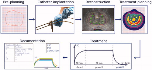
shows the workflow of IHT, which consists of: preplanning, catheter implantation, reconstruction, hyperthermia treatment planning, treatment with heat up phase (I), therapeutic phase (II) and cool down phase (III), and finally documentation. The target volume is always defined by the responsible clinician. Definition of the tumor volume, adjacent normal organs, OARs, and large vessels is one of the most important aspects of the treatment planning process, so it should incorporate the information from clinical examination and radiologic studies (US, computed tomography (CT), magnetic resonance imaging (MRI), Positron-emission tomography-computed tomography (PET-CT). CT or US guidance is used to place the catheters into the tumor target volume. In case of combining brachytherapy with hyperthermia, the clinical target volumes for both treatments should be the same. The geometry of the implant catheters should take into account brachytherapy physics, as well as technical properties of the heat sources [Citation9] and the required number and position of thermometry probes.
Figure 1. Schematic workflow of interstitial hyperthermia which consists of preplanning, catheter implantation, reconstruction, hyperthermia treatment planning, treatment with heat up phase (I), therapeutic phase (II) and cool down phase (III), and finally documentation.
Preplanning
Pretreatment planning involves definition of the target volume by the responsible clinician, more specifically the number, location and orientation of IHT applicators and thermometry to cover the desired target volume, taking into account the required applicator alignment, spacing and margins needed to ensure adequate tumor heating. Both patient-specific and generic nonpatient-specific planning using published implantation guidelines for specific techniques are acceptable [Citation8,Citation9]. Interstitial hyperthermia is generally applied using catheters implanted for brachytherapy, so planning should take the implant requirements for both radiotherapy and hyperthermia into account. A catheter spacing of 10 mm is optimal general practice for both modalities.
Catheter implantation
Catheters for applicators should use materials compatible with the hyperthermia technique used, for instance plastic catheters without self-heating should be used in conjunction with EM techniques [Citation49]. Catheters should be distributed homogeneously and parallel orientation throughout the target volume including the periphery to avoid hot spots as well as areas of underdosage. The goal temperature is 40–44 °C throughout the target volume combined with sparing of organs at risk and critical structures. Homogeneity of heating will be improved by reducing the spacing between catheters. Alternatively, accepting higher temperatures close to the catheters will help to reach the minimum temperature.
Catheters for thermometry should use the same materials as catheters for applicators. They should be placed at:
– representative locations for best sampling of target temperature.
– expected cold regions, that is, at the periphery and at target locations at a large distance from applicators
– close to critical structures
– expected hot spots
Table 1. Recommended minimum number* of temperature probes.
Reconstruction
Reconstruction of the treatment setup should be performed by 3D-imaging with CT, MR, or US with the patient in treatment position including the IHT catheters or applicators. Implant catheters should be visualized for proper tracking and localization, using dummy inserts if needed to recognize the catheter positions. The gross tumor volume (GTV) and hyperthermia target volume (HTV) should be defined.
Planning
Definitive treatment planning: The actual/updated gross tumor volume (GTV) and hyperthermia target volume (HTV) should be defined in the 3 D patient data set. Hereafter, the physicist/engineer can calculate the tissue insertion length of each catheter, the HTV along that length, the definite location of the applicators and temperature probes together with the steering parameters. If necessary, an offset to the applicator or thermometry insertion can be applied to match insertion depth to target volume.
Treatment
The operator should have all relevant data to control the treatment (temperature, dose, power, time - history) presented in the graphical user interface (GUI). Safeguards to detect and prevent malfunctioning of equipment, such as reflected power monitoring, should be present. Applicators and temperature probes are placed in the catheters. Hereafter, the treatment starts using low power. During the first 10 min the power is stepwise increased, after every power increase the temperatures and vital signs of the patient are monitored. The remaining treatment time after reaching steady-state (temperature T > 40 °C) should be between 30 to 60 min. Temperatures should be recorded at least every minute. If temperature mapping is used a cycle time for the temperature profiles of at most 5–10 min is recommended. Recording the temperature decay for several minutes after turning off the power is recommended. Most if not all patients will be on epidural and pain meds already, but during ‘breakthrough’ discomfort additional meds can be given or the applied power distribution can be altered or reduced if deemed necessary from patient feedback,.
Documentation
Treatment data to be recorded include temperatures of tumor and normal tissues at risk, tumor thermal dose, applied power to each applicator, temperature and flow of the cooling medium (if applicable), and operator and patient comments (e.g., pain). Calculating and recording temperature parameters T50 and T90, the temperatures achieved in 50% and 90% of measured (tumor-related) points, respectively, and CEM43T90 (CEM for ‘cumulative equivalent minutes’) is recommended, but challenging in view of the heterogeneous temperature distribution during IHT. Temperatures recorded using dedicated thermometry catheters will generally provide the minimum target temperature. Accurate dose distribution data are needed to obtain reliable T90 and CEM43T90 correlated with clinical response. The full list of parameters to document is given in Section IV-B.
Throughout planning and treatment delivery, HT should be done in such a way as to minimize impact on standard brachytherapy practice.
Part III. Technical considerations
III-A key characteristics of interstitial applicator devices
Interstitial applicators in use today consist of MW antennas, capacitively coupled radiofrequency catheter-based electrodes (RF-CC), resistively coupled radiofrequency local current field electrodes (RF-LCF), and ultrasound transducers. In general, these devices deposit energy within a limited volume of tissue close to the heating device(s). The operating principles of various systems for interstitial heating have been reviewed previously [Citation9,Citation51–53] and are summarized in Appendix B and C.
Heating uniformity within an interstitial implant array is highly dependent on: (i) modality and technical properties of the applicator used; (ii) implant spacing and alignment; and (iii) applicator position within each needle or catheter implant relative to the skin and other applicators. The comparison of critical implant characteristics given in for four different interstitial heating techniques provides some guidance in selecting the appropriate technique for a specific tumor indication.
Table 2. Comparison of device characteristics for four interstitial heating modalities.
As indicated in , RF-LCF techniques are most sensitive to parallel alignment of sources and MW antennas are more sensitive to alignment than US segmented linear array applicators that can be adjusted in power along the length to accommodate variable distance between implants. An important factor determining the required spacing is the characteristic heat penetration depth (PD) of the applicator. The PD of RF techniques is conservatively defined by 1/r2 falloff. Theoretically, higher PD can be achieved in the central part of the target volume with an array of multiple parallel MW applicators, if used in (nonrecommended) coherent mode. A special case exists for synchronous or coherent phase modes using a 20 × 20 mm implant utilizing the nonoccupied catheters for temperature measurement and feedback. To cover larger target volumes, ultrasound devices with the highest PD shall be preferably used to minimize the number of heating elements needed. This increase in PD justifies an increase in required implant array spacing from 10-15 mm for RF-CC/RF-LCF/MW techniques to 15–20 mm for US transducers, as listed in . The PD of MW antennas can be improved by selecting a lower operating frequency up to a certain limit [Citation54]. Some techniques apply internal cooling to reduce the maximum temperature at the applicator surface. This allows the operator to raise the applied power without overheating the applicator surface, effectively increasing the PD by a few mm. This allows a corresponding increase in implant spacing over non-cooled applicators. A practical implication for this approach is that maximum temperature Tmax cannot be acquired in or near the applicator.
III-B characterization of heating properties
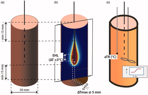
The implant/applicator is usually characterized as a single device, but clinically applied in an array of applicators. An IHT system should be capable of increasing the temperature throughout the target volume to the desired therapeutic range of 40–44 °C. To achieve this, an individual implant/applicator should be able to deposit at least 0.5W/g in its subvolume of the implant volume [Citation25,Citation55]. Characterization of the applicator’s heating properties should be performed annually and consist of measuring the heating pattern () and its efficiency ().
Figure 2. The two main experimental setups to characterize the heating properties of an interstitial applicator. (a) Schematic setup to determine the effective heating length and the average temperature rise (aTR) in muscle equivalent phantoms, (b) Determination of the effective heating length in a solid phantom and using infrared imaging (ΔTmax ≥ 6 °C), (c) Calorimetric setup to determine the applicator efficacy in a liquid phantom for 6 min heating time. The temperature–time profile must be measured 5 min before and after the heating and continuing during heating while continuously homogenizing the liquid to obtain the correct average temperature. The minimum average ΔT must be 6 °C.
(1) Single applicator
Prior to clinical use, the properties of the IHT system must be characterized. First, it has to be demonstrated whether the effective heating length (EHL) is sensitive for insertion depth. The minimum dimension of the experimental setup to characterize the IHT system are shown in . Therefore the temperature pattern must be measured for two different insertion depths, for example, 5 and 25 mm between the phantom surface and the active part of the applicator, in a split muscle equivalent phantom used in combination either with an IR camera (preferred) or with liquid crystal film [Citation56] which both need calibration before use, with a resolution of ±0.1 °C and relative accuracy 0.05 °C; spatial resolution 0.5–1 mm [Citation7] (). These patterns should be available for the physicist prior to geometric planning. EM field measurements using E-field probes is not recommend, due to severe limitations with spatial resolution [Citation57,Citation58]. Furthermore, a calorimetric measurement to determine efficiency of the applicator must be performed as described by Wilkinson et al [Citation59] (). Knowledge of applicator efficiency is mandatory for hyperthermia treatment planning or setting power output per applicator using synchronous or coherent arrays.
In general MW, RF-CC and Ultrasound interstitial applicators are used without counter electrodes. Only for RF-LCF the application is mostly with a single ‘hot’ electrode and a large counter electrode outside but against the body surface. For all these cases, the characteristic heating properties can be assessed as described in next sections. In rare cases, RF-LCF heating is achieved by using two internal electrodes. For this special case, the characteristic heating properties can also be assessed using the description below, but the single applicator has to be replaced by the dual electrode setup and the diameter of the phantom cylinder has to be doubled. Hence, the picture in ) holds two electrodes with heating patterns.
Temperature rise criteria for adequate heating
An interstitial heating applicator is considered adequate/appropriate if a temperature rise (TR) of 6 °C above the starting temperature can be achieved in 6 min in a muscle-equivalent phantom [Citation7], around the applicator at 5 mm, in general a distance equal to half the implant spacing, .
The effective heating length depends on the applicator design and can be determined using the measurement described in section III-B (1). The EHL is characterized by a thermal profile in the vertical plane, as shown in . Similarly to Emami et al [Citation8], the EHL is defined as the length at which the temperature rise (TR) is 50% or more of the maximum TR (i.e., temperature difference ΔT ≥ 3 °C) obtained a constant distance of 5 mm from the applicator. The phantom can be cylindrical as shown in , or flat but should be sufficiently large to show the entire heating pattern.
Note that besides characterizing the temperature distribution, the effectively applied power must be measured annually. This can be accomplished with a calorimetric method using a cylinder of which the diameter depends on the heating device (). The diameter of the cylinder should be much larger than the implant spacing to reduce the effects of the outer boundary on the measurement; and >30 mm minimum irrespective of applicator type. Theoretically, it seems possible to calculate the total absorbed power from average temperature rise (aTR) measurements, but this approach has limited accuracy since it includes self-heating of the applicator as well as the EM deposited energy.
Thus shows the appropriate setup for calorimetric/effective power measurements. The applicator within the planned brachytherapy catheter is immersed in a Styrofoam isolated cylinder of given diameter with a length of a liquid muscle-equivalent phantom [Citation60] matching the active length of the applicator, where the phantom should extend 15 mm before and after the active part of applicator. The initial temperature of the phantom must be known, typically at room temperature or other stable uniform temperature. The maximum power is applied for maximally 6 min to achieve at least a 6 °C temperature rise. As an example: to increase the temperature of a saline volume by 6 °C during a 6 min heating time an average SAR of 70 W/kg is required. For a 3 cm diameter cylinder that is 10 cm long (i.e., a volume of 70.9 cm3 and a weight of 0.0709 kg), this translates in an applied power level of 5 W. The aTR in the phantom is measured before and after by a temperature probe following good mixing of the liquid to obtain a homogeneous temperature. The effective power emitted by the applicator can be calculated from the relation
in which Pa is absorbed power, ρ is the density and cw is the specific heat capacity of the muscle-equivalent saline water, V is the volume, dT the temperature increase, dt is the duration of heating. Alternatively, if other liquid media are used the calorimeter can be calibrated by a resistance wire heating element, and direct current (DC) and applied voltage measured to provide dT per unit power deposited.
(2) Array of applicators
It is important to verify to which degree applicators are performing independently regarding heating pattern and power output of each applicator, and whether these remain stable and controllable when other applicators power channels in the array are switched on or off. Such a test should be done with an asynchronous or incoherent phase mode for these channels. Generally, each applicator is operated by a separate, independently controlled power control channel. Verification of this independence is particularly important when multiple applicators are connected to a single power channel, for example, through a power splitter or similar device. The setup shown in should be used to test and verify the stability of the heating pattern of applicators within an array as individual applicator or part of an applicator array operated by a single power control. LCF applicators are more sensitive for misbalance when multiple applicators are operated by a single power control than MW applicators using a calibrated power divider.
The first test involves the temperature distribution in the horizontal plane through the maxima of Tmax when all applicators are switched on as depicted in . This requires a phantom filled with a muscle equivalent gel which can be split at the mid horizontal plane to permit recording of the temperature distribution using a thermographic camera as outlined in the superficial hyperthermia guidelines [Citation6,Citation7].
The test of the stability of the heating pattern of applicators and their generators is performed using an implant of three applicators inserted in a phantom filled with a muscle equivalent gel as depicted in . A temperature probe is inserted at 5 mm distance from each applicator to monitor the effective output of each applicator. Applicators should be switched on and off in different configurations with the objective to establish that the effective power output of each applicator remains stable independent of the on/off status of the other two applicators. In this case, the RF-LCF applicators must be operated as a unipolar system with a large ground plate connected to tissue. In systems using multiple applicators per power channel, the applicators should be connected to a single channel as well as distributed over different channels. An example is given for three applicators. We will compare the effective output power by continuously measuring the temperature rise close to the first applicator during 3 minutes of power on for three settings: 100, 101 and 111. For systems with a minimum measured temperature, for example, 29 °C for the BSD 500, the phantom will need to be prewarmed so that the stated rise rate can be observed. The first experiment is the control measurement with one applicator switched on (setting 100). In the second experiment, the first and third applicators are switched on (setting 101). Any change in effective output power as a result of switching on these applicators indicates an influence of the generator as the mutual distance of the first and third applicator is 40 mm, too large for direct interference between the applicators. Finally, in the third experiment, all three applicators are switched on (setting 111). This final measurement may also establish a more direct interference between applicators if switching on of this applicator at a closer distance has more impact than switching on the furthest applicator. The test should be performed as a single experiment, that is, without moving applicators and temperature sensors. A variation less than +/-20% for each temperature sensor/applicator pair within all three experiments is considered acceptable. The forward, reflected, and net power should also be recorded for each applicator and test situation, and used for consistency. This procedure should also establish that the output is indeed zero when an applicator is switched off.
Figure 3. Setup to verify independent performance of three applicators in an array. Experiments are required for three configurations with a different combination of active applicators. (a) Setup to test the independence of the applicators and their generators, consisting of three applicators, each 20 mm apart, and three temperature probes indicated in black, each recording the temperature at 5 mm of the active section of one applicator. (b) Example showing temperature distributions in the horizontal plane at the position of the maxima of Tmax when one, two or three applicators are switched on. Green dots indicate power on, red dots power off.
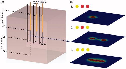
For testing an array of three applicators that share the same RF power channel with a power divider or when an array of three applicators are operated in a phase synchronous mode, the simultaneous operation of all three applicators with equal RF power should be tested to verify that the measured heating rates do not vary by more than ±20%. If it is not possible to switch connections to different applicators of a power divider using a single channel than the applicator cables should be connected or disconnected from the output of the power splitter. For such a case, the input power to the power divider would need to be changed so that the RF power to each of these applicators would be the same. A synchronous phased array of three applicators can have RF power of individual channels switched on or off, but for such a test the temperature sensor of the central applicator may have a higher heating rate compared to the perimeter applicators due to the synchronous phase additive effects when all 3 applicators are operated.
III-C benefits of 3 D treatment planning
Although 3 D hyperthermia treatment planning systems are scarcely used as a routine part of the interstitial hyperthermia workflow, they have great potential to increase the insight and understanding of the quality of the applied heat distribution. Phantom measurements are generally unable to produce quantitative metrics like T10, T50, and T90, whereas these parameters are readily calculated with treatment planning systems. The benefits of planning software are especially useful in cases of irregular implants which deviate from equally spaced implants, or when insertion depths are variable. Simulations can help to determine the required applicator spacing for optimal target heating. If the insertion depth is shallow for a particular source, care must be taken to ensure that the SAR profile is as expected and not unintentionally preferentially heating tissue proximal to the target (e.g., bulb of penis, vaginal wall), or skin surface around the entrance site. Hyperthermia treatment planning is generally invaluable for initial evaluation of novel interstitial hyperthermia applicators or implant configurations.
For microwave heating using commercial systems, built-in planning tools can be used to simulate heating according to a user defined placement of the applicators and adjusted phase and power settings. In general, an important aspect for treatment planning in interstitial hyperthermia is accurate modeling of the applicators. For capacitively coupled interstitial electrodes, a grid-independent representation allows an accurate description of irregular implants in heterogeneous tissue [Citation61]. Available techniques for modeling interstitial ultrasound devices have been reviewed by Prakash et al. [Citation62]. In multi-element systems, the interaction between the individual elements has a substantial impact on the achieved temperature distribution. For instance, a graded-mesh finite-difference time-domain (FDTD) code, together with an alternate-direction-implicit finite-difference (ADI-FD) solution of the bioheat equation, were used for studying arrays of sleeved-slot antennas imbedded in a brain-equivalent phantom [Citation63]. Patient-specific temperature-based optimization techniques are being developed for these complex systems [Citation64] and can be expected to improve future treatments.
At this time, the use of more detailed forward and optimization-based treatment planning systems for interstitial hyperthermia–is limited to a few academic centers that study specific patient cases with, whenever possible, validation of the predicted SAR/temperature distribution with measurements made during the patient treatment [Citation65,Citation66]. From these experiences, recommendations for treatment have been formulated in the literature for some general cases (e.g., implant technique, proximity of bone, insertion depths, synchronous versus asynchronous operation) that can be applied by the hyperthermia community [Citation66,Citation67].
Generic pretreatment planning is the minimum requirement and most basic form of planning system. This involves computing the SAR and temperature distribution in an equally spaced implant of applicators placed in an (semi) infinite (half) space, assuming appropriate homogeneous tissue properties and perfusion. The characteristics of the heating device for various insertion depths into soft tissue need to be accounted for. The reliability of generic planning is limited, but tumor temperatures will not be overestimated if worst case assumptions are made regarding tissue and perfusion properties, for example, assuming the maximally increased tissue perfusion rate valid in response to hyperthermic temperatures. This generic pretreatment planning is very useful to derive generic rules for implant properties including active applicator length, spacing and location. If available, individual patient-specific treatment planning is recommended using relevant anatomical data with perfusion and tissue properties acquired using CT, MRI or US [Citation64,Citation67,Citation68].
In clinical application, computer simulations are useful to complement actual measurements and thereby estimate the indexed temperatures T10, T50 and T90, particularly in view of the high gradients, small heated volume, and potentially complex interactions within multi-element systems.
Nevertheless it is important to take into account the uncertainties and limitations of the temperature simulation in the planning systems.
IV. Protocol compliance, staff and documentation
IV-A demands on personnel
Hyperthermia is a multidisciplinary treatment involving complex interrelated clinical and technical aspects. It requires input and close cooperation of radiation oncologists, medical oncologists, medical physicists, engineers, technicians, nurses and in some cases surgeons and anesthesiologists. Recommendations and responsibilities for all hyperthermia treatment staff, with the exception of surgeons, are summarized in [Citation4,Citation69]. Local and country-specific regulations must be respected.
(a) Hyperthermia training
For the staff members who actually apply the interstitial hyperthermia practical training in the form of active participation at an established hyperthermia center is required, in addition to their main qualification. Adequate practical training is defined as at least 10 treatment sessions be performed with the heating system in 3–5 different patients, under the guidance of an experienced user. If the person in training has experiences with other hyperthermia modalities (at least 1 year superficial/deep HT), the required training reduces to five treatment sessions. It is recommended that the training period is completed in 6 months. Staff members who just take care of the patients’ well-being and are not directly involved in the application of the interstitial hyperthermia need only a basic training on the principles hyperthermia and the possible physiological effects of interstitial heating. A modified training procedure can be discussed with ESHO in case of severe practical obstacles, for example, the absence of an established interstitial hyperthermia institute within a reasonable distance.
(b) Physicians
Interstitial Hyperthermia treatments are performed under the supervision of a radiation oncologist who has been adequately trained in either brachytherapy and/or theory and clinical practice of interstitial hyperthermia. The physician is responsible for all clinical aspects of the hyperthermia treatment (e.g., diagnosis, imaging, patient selection, treatment prescription, fractionation, documentation). The physician is responsible for implantation of an appropriate high-quality hyperthermia catheters implant. This includes complete coverage of the target volume, protection of organs at risk, and optimal separation and parallel orientation of catheters. The physician should understand the limitations of interstitial heating technology when placing the implant catheters, to ensure optimal insertion length, alignment, and density for both radiation and hyperthermia considerations. In case of a challenging location, the physician can invite a surgeon to place the implant catheters. Further, the physician also takes care of additional medications for pain management and breakthrough pain if needed.
(c) Physicists/engineers
An adequately trained physicist or engineer is responsible for the physical and technical aspects of the hyperthermia system (e.g., quality assurance and consistency checks, specifying the technical treatment parameters, intervention in case of technical failures, phantom measurements, physical–technical part of the treatment planning) as described in this document. In the preplanning phase, the physicist/engineer must always advise the initial setup with the oncologist, which defines the desired catheter positions and optimized power delivery preplan.
(d) Technicians
The interstitial hyperthermia treatment can be assigned to a hyperthermia trained assistant, for example a Radiation Therapist or Radiographer under the direct supervision of a physician and physicist. The technical assistant should be specifically trained in the application of interstitial hyperthermia, with minimum training defined in section a) above. If the hyperthermia equipment is operated by a technician, the responsible physicist must be on-call and ready to take direct action (maximum acceptable response time 5 min).
(e) Nurses
Nurses can support a medical technician to perform interstitial hyperthermia treatments after completing a training program. In most institutes, nurses are involved in the preparation of patients for the hyperthermia treatment and are responsible for the well-being of the patient (e.g., assist with placement of interstitial catheters for applicators and thermometry, monitoring of patient vital signs during therapy, administration of analgesics and pain medications, etc.). When properly trained according to the physicist or treatment technician requirements above, the nurse may perform the hyperthermia treatment.
(f) Anesthetists
When sedation of the patient is required, an anesthetist performs all relevant actions. A potential assistant must be formally trained in anesthesia.
(g) Arranging substitutes
As in many other clinical treatments, two of the previously described responsible professionals must be present at the beginning of each treatment session in order to take care of the patient, to control the hyperthermia device, and to guarantee correct implementation and verification of all aspects of the standard operational procedure (SOP). During treatment, one person might be sufficient if the other is available on call. When interstitial hyperthermia is applied in combination with chemotherapy, a second person is responsible for the chemotherapy application as described in the SOP for chemotherapy.
IV-B treatment documentation
Treatment documentation varies for different complexity levels of clinical use of IHT. The minimum data set required to reconstruct the treatment quality of ‘a standard treatment’ is defined below. Multicenter trials and dose effect studies generally require a higher level of documentation as summarized in Appendix A.
Interstitial hyperthermia presents an opportunity for temperature measurement directly within and adjacent to tumors at depth which is generally not possible with superficial temperature monitoring. Rigorous temperature measurement throughout the treatment region is encouraged, balanced with practical treatment considerations including the total number of catheters required for radiation treatment and temperature probe placement.
Temperature data are preferably reported using maximal, minimal and average temperatures Tmax, Tmin, Tave, and the temperature parameters T10, T50, and T90, which are the temperatures achieved in 10%, 50% and 90% of (tumor-related) measured points, respectively. These parameters give a fair representation of the temperature distribution during treatment when a sufficient number of temperatures are monitored with appropriate spatial sampling as described in the clinical study protocol. Thus the number of sensors and the volume enclosed by the sensors in relation to the target volume should be recorded to reflect the quality of the temperature dosimetry.
When analyzing the achieved temperatures during IHT, attention must be given to the position of the thermal sensors with respect to the applicators. Temperatures recorded using sensors placed separately in tissue between sensors typically correlate with cold spots, giving values close to Tmin and T90. Sensors integrated within or adjacent to the applicators generally provide information about maximal temperatures Tmax and T10. Moreover, there are variations of temperature along the length of the applicators so that higher quality dosimetry results from increasing the number of measurement locations along each temperature monitoring catheter as well as the number of probes/catheters. Placement of temperature points and mapping to include tumor periphery at the distal and proximal extent of implant, and within the implant interior are all critical to assess the quality of delivered treatment. However, the perimeter of tumors is generally well-perfused making those tissues more sensitive to radiation or chemotherapy alone. So the clinical impact of adding IHT may have more importance based on the temperatures within the more necrotic portions of the tumor that would be more resistant to radiation or chemotherapy.
Minimum requirements for data reporting
All treatment relevant system control parameters (e.g., power, reflection, etc.) as well as all temperature measurement values must be stored at regular time intervals, for example, every five minutes. Changes to the treatment parameters must be documented with chronological reference. Temperatures must be documented in a manner that they can be related chronologically to the corresponding measurement location. Further, logging must be performed of power-related pain, pain caused by the position of the applicator or the applicator itself, treatment interruptions or early termination. Acute and late toxicities must also be recorded. Storing treatment data should preferably follow a joint standard format. The published data standard for the storage and interchange of hyperthermia clinical data could serve as a starting point to address this issue [Citation12].
Disclaimer
This publication is based on literature and other sources of information judged to be reliable by the authors representing the ESHO-TC. However, the authors, ESHO-TC and editors disclaim any warranty or liability based on or relating to the contents of this publication. The authors and ESHO-TC do not endorse any specific products, manufacturers, or suppliers. Nothing in this publication should be interpreted as implying such endorsement. Several companies were invited to provide feedback on the document but have not participated actively either at ESHO-TC meetings or in the writing of this document. The authors and ESHO-TC alone are responsible for the content and writing of this paper.
Disclosure statement
No potential conflict of interest was reported by the authors.
References
- IAH. Available from: http://www.hyperthermie.org.
- ESHO. Available from: www.esho.info
- STM. Available from: http://www.thermaltherapy.org/eBusSFTM/.
- Bruggmoser G. Some aspects of quality management in deep regional hyperthermia. Int J Hyperther. 2012;28:562–569.
- Bruggmoser G, Bauchowitz S, Canters R, et al. Guideline for the clinical application, documentation and analysis of clinical studies for regional deep hyperthermia. Strahlenther Onkol. 2012;188:198–211.
- Dobsicek Trefna H, Crezee H, Schmidt M, et al. Quality assurance guidelines for superficial hyperthermia clinical trials: I. Clinical requirements. Int J Hyperthermia. 2017;33:471–482.
- Dobsicek Trefna H, Crezee J, Schmidt M, et al. Quality assurance guidelines for superficial hyperthermia clinical trials: II. Technical requirements for heating devices. Strahlenther Onkol. 2017;193:351–366.
- Emami B, Stauffer P, Dewhirst MW, et al. RTOG quality assurance guidelines for interstitial hyperthermia. Int J Radiat Oncol Biol Phys. 1991;20:1117–1124.
- Stauffer PR, Diederich CJ, Seegenschmiedt MH. Interstitial heating technologies. In: Seegenschmiedt MH, Fessenden P, Vernon CC, editors. Thermoradiotherapy and thermochemotherapy: Volume 1, Biology, Physiology and Physics. Berlin, New York: Springer-Verlag; 1995. p. 279–320.
- Visser AG, Chive M, Hand MW, et al. Interstitial and intracavitary hyperthermia. A Task Group Report of the European Society for Hyperthermic Oncology in cooperation with a COMAC-BME Concerted Action within the 4th Medical and Health Research Programme of the European Commission. Rome: Postgraduate school of Medical Physics University of Rome Tor Vergata: 1993.
- Hand JW, Lagenduk JJW, Andersen JB, et al. Quality Assurance Guidelines for Esho Protocols. Int J Hyperther. 1989;5:421–428.
- Sapareto SA, Corry PM. A proposed standard data file format for hyperthermia treatments. Int J Radiat Oncol Biol Phys. 1989;16:613–627.
- Datta NR, Rogers S, Klingbiel D, et al. Hyperthermia and radiotherapy with or without chemotherapy in locally advanced cervical cancer: a systematic review with conventional and network meta-analyses. Int J Hyperthermia. 2016;32:809–821.
- Issels R, Kampmann E, Kanaar R, et al. Hallmarks of hyperthermia in driving the future of clinical hyperthermia as targeted therapy: translation into clinical application. Int J Hyperthermia. 2016;32:89–95.
- Frey B, Ruckert M, Deloch L, et al. Immunomodulation by ionizing radiation-impact for design of radio-immunotherapies and for treatment of inflammatory diseases. Immunol Rev. 2017;280:231–248.
- Dewhirst MW, Stauffer PR, Das SK, et al. Hyperthermia In: Gunderson L, Tepper J, editors. Clinical radiation oncology. 4th ed. Philladelphia: Elsevier; 2016. p. 381–398.
- Hoffman RM, Monga M, Elliott SP, et al. Microwave thermotherapy for benign prostatic hyperplasia. Cochrane Database Syst Rev. 2012(9);CD004135.
- Dewhirst MW, Vujaskovic Z, Jones E, et al. Re-setting the biologic rationale for thermal therapy. Int J Hyperthermia. 2005;21:779–790.
- Leopold KA, Dewhirst MW, Samulski TV, et al. Cumulative minutes with T90 greater than Tempindex is predictive of response of superficial malignancies to hyperthermia and radiation. Int J Radiat Oncol Biol Phys. 1993;25:841–847.
- Oleson JR, Samulski TV, Leopold KA, et al. Sensitivity of hyperthermia trial outcomes to temperature and time: implications for thermal goals of treatment. Int J Radiation Oncol Biol Phys. 1993;25:289–297.
- van Rhoon GC. Is CEM43 still a relevant thermal dose parameter for hyperthermia treatment monitoring?. Int J Hyperthermia. 2016;32:50–62.
- Overgaard J. Simultaneous and sequential hyperthermia and radiation treatment of an experimental tumor and its surrounding normal tissue in vivo. Int J Radiat Oncol Biol Phys. 1980;6:1507–1517.
- Hulshof MCCM, Raaymakers BW, Lagendijk JJW, et al. A feasibility study of interstitial hyperthermia plus external beam radiotherapy in glioblastoma multiforme using the Multi Electrode Current Source (MECS) system. Int J Hyperthermia. 2004;20:451–463.
- Overgaard J. The current and potential role of hyperthermia in radiotherapy. Int J Radiat Oncol Biol Phys. 1989;16:535–549.
- Adibzadeh F, Paulides MM, van Rhoon GC. SAR thresholds for electromagnetic exposure using functional thermal dose limits. Int J Hyperthermia. 2018;34:1248–1254.
- Stauffer PR. Evolving technology for thermal therapy of cancer. Int J Hyperthermia. 2005;21:731–744.
- Seegenschmiedt MH, Sauer R. Interstitial and intracavitary thermoradiotherapy. Berlin Heidelberg New York London, Paris, Tokyo, Hong Kong Barcelona, Budapest: Springer-Verlag; 1993.
- Ryan TP. Comparison of six microwave antennas for hyperthermia treatment of cancer: SAR results for single antennas and arrays. Int J Radiation Oncol Biol Phys. 1991;21:403–413.
- Panjehpour M, Overholt BF, Milligan AJ, et al. Nd:YAG laser-induced interstitial hyperthermia using a long frosted contact probe. Lasers Surg Med. 1990;10:16–24.
- Astrahan MA, Norman A. A localized current field hyperthermia system for use with 192-iridium interstitial implants. Med Phys. 1982;9:419–424.
- Corry PM, Martinez A, Armour EP, et al. Simultaneous hyperthermia and brachytherapy with remote afterloading. In: Martinez AA, Morton CT, Mould RF, editors. Brachytherapy HDR and LDR. Proceedings of the meeting “Remote Afterloading: State of the Art”; Colombia, MD, Dearborn, MI: Nucletron Corp; 1990. p. 193–204
- Visser AG, Deurloo IKK, Levendag PC, et al. An Interstitial hyperthermia system at 27-Mhz. Int J Hyperthermia. 1989;5:265–276.
- Kaatee RSJP, Crezee H, Kanis BP, et al. Spatial temperature control with a 27 MHz current source interstitial hyperthermia system. Int J Radiation Oncol Biol Phys. 1997;37:189–197.
- Van der Koijk JF, Lagendijk JJW, Crezee J, et al. The influence of vasculature on temperature distributions in MECS interstitial hyperthermia: importance of longitudinal control. Int J Hyperthermia. 1997;13:365–385.
- Lesnicar H, Budihna M, Handl-Zeller L, et al. Clinical experience with water-heated interstitial hyperthermia system. Acta Chir Austriaca. 1992;24:214–216.
- DeFord JA, Babbs CF, Patel UH, et al. Effective estimation and computer control of minimum tumour temperature during conductive interstitial hyperthermia. Int J Hyperthermia. 1991;7:441–453.
- Stauffer PR, Cetas TC, Fletcher AM, et al. Observations on the use of ferromagnetic implants for inducing hyperthermia. IEEE Trans Biomed Eng. 1984;31:76–90.
- Tucker RD, Platz CE, Huidobro C, et al. Interstitial thermal therapy in patients with localized prostate cancer: histologic analysis. Urology. 2002;60:166–169.
- Patel UH, DeFord JA, Babbs CF. Computer-aided design and evaluation of novel catheters for conductive interstitial hyperthermia. Med Biol Eng Comput. 1991;29:25–33.
- Prionas SD, Kapp DS, Goffinet DR, et al. Thermometry of interstitial hyperthermia given as an adjuvant to brachytherapy for the treatment of carcinoma of the prostate. Int J Radiat Oncol Biol Phys. 1994;28:151–162.
- Mack CF, Stea B, Kittelson JM, et al. Interstitial thermoradiotherapy with ferromagnetic implants for locally advanced and recurrent neoplasms. Int J Radiat Oncol Biol Phys. 1993;27:109–115.
- Lagendijk JJW, Visser AG, Kaatee RSJP, et al. Interestitial hyperthermia & treatment planning: the 27 MHz multi-electrode current source method. Nucletron-Odelft Activity Report No 6; 1995. p. 83–90.
- Diederich CJ, Khalil IS, Stauffer PR, et al. Direct-coupled interstitial ultrasound applicators for simultaneous thermobrachytherapy: a feasibility study. Int J Hyperthermia. 1996;12:401–419.
- Diederich CJ. Ultrasound applicators with integrated catheter-cooling for interstitial hyperthermia: theory and preliminary experiments. Int J Hyperthermia. 1996;12:279–297.
- Nau WH, Diederich CJ, Stauffer PR. Directional power deposition from direct-coupled and catheter-cooled interstitial ultrasound applicators. Int J Hyperthermia. 2000;16:129–144.
- Stauffer PR, Goldberg SN. Introduction: thermal ablation therapy. Int J Hyperthermia. 2004;20:671.
- Diederich CJ. Thermal ablation and high-temperature thermal therapy: overview of technology and clinical implementation. Int J Hyperthermia. 2005;21:745–753.
- Pieters BR, van der Grient JN, Blank LE, et al. Minimal displacement of novel self-anchoring catheters suitable for temporary prostate implants. Radiother Oncol. 2006;80:69–72.
- van der Koijk JF, Crezee J, Lagendijk JJW. Thermal properties of capacitively coupled electrodes in interstitial hyperthermia. Phys Med Biol. 1998;43:139–153.
- Kukielka AM, Hetnal M, Brandys P, et al. Interstitial hyperthermia of the prostate in combination with brachytherapy: an evaluation of feasibility and early tolerance. Strahlenther Onkol. 2013;189:467–475.
- Hand JW, Trembly BS, Prior MV. Physics of interstitial hyperthermia: radiofrequency and hot water tube techniques. In: Urano M, Douple E, editors. Hyperthermia and oncology, vol 3. Interstitial Hyperthermia. Zeist: VSP; 1991. p. 99–134.
- Handl-Zeller L, editor. Interstitial hyperthermia. Wien, New York: Springer-Verlag; 1992.
- Strohbehn JW. Interstitial techniques for hyperthermia. In: Field SB, Franconi C, editors. Physics and technology of hyperthermia. Dordrecht, Boston, Lancaster: Martinus Nijhoff Publishers; 1987. p. 211–240.
- Vrba J, Franconi C, Lapes M. Theoretical limits for the penetration depth of intracavitary applicators. Int J Hyperthermia. 1996;12:737–742.
- Dutz S, Hergt R. Magnetic nanoparticle heating and heat transfer on a microscale: basic principles, realities and physical limitations of hyperthermia for tumour therapy. Int J Hyperthermia. 2013;29:790–800.
- Cristoforetti L, Pontalti R, Cescatti L, et al. Quantitative colorimetric analysis of liquid crystal films (LCF) for phantom dosimetry in microwave hyperthermia. IEEE Trans Biomed Eng. 1993;40:1159–1165.
- Babij TM, Hagmann MJ, Gottlieb CF, et al. Evaluation of heating patterns of microwave interstitial applicators using miniature electric field and fluoroptic temperature probes. Int J Hyperthermia. 1991;7:485–492.
- Deardorff DL, Diederich CJ, Nau WH. Control of interstitial thermal coagulation: comparative evaluation of microwave and ultrasound applicators. Med Phys. 2001;28:104–117.
- Wilkinson DA, Saylor TK, Shrivastava PN, et al. Calorimetric evaluation of antennas used for microwave interstitial hyperthermia. Int J Hyperthermia. 1990;6:655–663.
- Hartsgrove G, Kraszewski A, Surowiec A. Simulated biological materials for electromagnetic radiation absorption studies. Bioelectromagnetics. 1987;8:29–36.
- de Bree J, van der Koijk JF, Lagendijk JJ. A 3-D SAR model for current source interstitial hyperthermia. IEEE Trans Biomed Eng. 1996;43:1038–1045.
- Prakash P, Salgaonkar VA, Diederich CJ. Modelling of endoluminal and interstitial ultrasound hyperthermia and thermal ablation: applications for device design, feedback control and treatment planning. Int J Hyperthermia. 2013;29:296–307.
- Pisa S, Cavagnaro M, Piuzzi E, et al. Power density and temperature distributions produced by interstitial arrays of sleeved-slot antennas for hyperthermic cancer therapy. Ieee Trans Microwave Theory Techn. 2003;51:2418–2426.
- Salgaonkar VA, Prakash P, Diederich CJ. Temperature superposition for fast computation of 3D temperature distributions during optimization and planning of interstitial ultrasound hyperthermia treatments. Int J Hyperthermia. 2012;28:235–249.
- Raaymakers BW, Van Vulpen M, Lagendijk JJ, et al. Determination and validation of the actual 3D temperature distribution during interstitial hyperthermia of prostate carcinoma. Phys Med Biol. 2001;46:3115–3131.
- van Vulpen M, Raaymakers BW, Lagendijk JJ, et al. Three-dimensional controlled interstitial hyperthermia combined with radiotherapy for locally advanced prostate carcinoma–a feasibility study. Int J Radiat Oncol Biol Phys. 2002;53:116–126.
- Scott SJ, Prakash P, Salgaonkar V, et al. Interstitial ultrasound ablation of tumors within or adjacent to bone: contributions of preferential heating at the bone surface. Energy-based Treatment of Tissue and Assessment VII. Proc. SPIE. 2013;8584.
- Chen X, Diederich CJ, Wootton JH, et al. Optimisation-based thermal treatment planning for catheter-based ultrasound hyperthermia. Int J Hyperthermia. 2010;26:39–55.
- Myerson RJ, Moros EG, Diederich CJ, et al. Components of a hyperthermia clinic: recommendations for staffing, equipment, and treatment monitoring. Int J Hyperthermia. 2014;30:1–5.
- Diederich C. Endocavitary and catheter-based ultrasound devices. In: Moros E, editor. Physics of thermal therapy. Boca Raton: CRC Press; 2013.
- Pyrexar Medical Inc. “BSD-500 Features”. [cited 2019 Jan 8] Available from: http://www.pyrexar.com/hyperthermia/bsd-500.
- Crezee J, der Koijk v, Kaatee Rsjp JF, Lagendijk JJW. Implications of using thermocouple thermometry in 27 MHz capacitively coupled interstitial hyperthermia. Phys Med Biol. 1997;42:637–650.
- Stuecklschweiger G, Arian-Schad KS, Kapp DS, et al. Analysis of temperature distributions of interstitial hyperthermia using a hot water system. Int J Radiat Oncol Biol Phys. 1993;26:891–895.
- Wootton JH, Prakash P, Hsu IC, et al. Implant strategies for endocervical and interstitial ultrasound hyperthermia adjunct to HDR brachytherapy for the treatment of cervical cancer. Phys Med Biol. 2011;56:3967–3984.
- Diederich CJ, Wootton J, Prakash P, et al. Catheter-based ultrasound hyperthermia with HDR brachytherapy for treatment of locally advanced cancer of the prostate and cervix. Proc SPIE Int Soc Opt Eng. 2011;7901:79010O.
- Salgaonkar VA, Diederich CJ. Catheter-based ultrasound technology for image-guided thermal therapy: current technology and applications. Int J Hyperthermia. 2015;31:203–215.
- Commission IE. IEC 61161 Ultrasonics - Power measurement - Radiation force balances and performance requirements Edition 3.0. Geneva, Switzerland 2013.
- Wootton JH, Hsu IC, Diederich CJ. Endocervical ultrasound applicator for integrated hyperthermia and HDR brachytherapy in the treatment of locally advanced cervical carcinoma. Med Phys. 2011;38:598–611.
- Crezee H, Inman BA. The use of hyperthermia in the treatment of bladder cancer. Int J Hyperthermia. 2016;32:349–350.
- van Valenberg H, Colombo R, Witjes F. Intravesical radiofrequency-induced hyperthermia combined with chemotherapy for non-muscle-invasive bladder cancer. Int J Hyperthermia. 2016;32:351–362.
- Sousa A, Pineiro I, Rodriguez S, et al. Recirculant hyperthermic IntraVEsical chemotherapy (HIVEC) in intermediate-high-risk non-muscle-invasive bladder cancer. Int J Hyperthermia. 2016;32:374–380.
- Stauffer PR, van Rhoon GC. Overview of bladder heating technology: matching capabilities with clinical requirements. Int J Hyperthermia. 2016;32:407–416.
- Schooneveldt G, Bakker A, Balidemaj E, et al. Thermal dosimetry for bladder hyperthermia treatment. An overview. Int J Hyperthermia. 2016;32:417–433.
- van der Heijden AG, Dewhirst MW. Effects of hyperthermia in neutralising mechanisms of drug resistance in non-muscle-invasive bladder cancer. Int J Hyperthermia. 2016;32:434–445.
- Kuijpers AM, Mirck B, Aalbers AG, et al. Cytoreduction and HIPEC in the Netherlands: nationwide long-term outcome following the Dutch protocol. Ann Surg Oncol. 2013;20:4224–4230.
- Eight Medical Corporation.
- Therma Solutions Inc. [cited 2018 Jan 8]. Available from: https://www.thermasolutions.com/.
- Gamida. [cited 2018 Jan 8]. Available from: http://www.gamida.net/.
- Rand. [cited 2018 Jan 8]. Available from: http://rand-biotech.com/.
- Diederich CJ, Hynynen K. The development of intracavitary ultrasonic applicators for hyperthermia: a design and experimental study. Med Phys. 1990;17:626–634.
- Hurwitz MD, Hansen JL, Prokopios-Davos S, et al. Hyperthermia combined with radiation for the treatment of locally advanced prostate cancer: long-term results from Dana-Farber Cancer Institute study 94-153. Cancer. 2011;117:510–516.
- Hurwitz MD, Kaplan ID, Hansen JL, et al. Hyperthermia combined with radiation in treatment of locally advanced prostate cancer is associated with a favourable toxicity profile. Int J Hyperthermia. 2005;21:649–656.
- Hurwitz MD, Kaplan ID, Hansen JL, et al. Association of rectal toxicity with thermal dose parameters in treatment of locally advanced prostate cancer with radiation and hyperthermia. Int J Radiat Oncol Biol Phys. 2002;53:913–918.
Appendix A
Analysis and documentation of treatments mandatory for institutes participating in clinical trials and recommended in general
Temperature data are preferably reported maximal, minimal and average temperatures Tmax, Tmin, Tave, and the temperature parameters T10, T50, and T90, which are the temperatures achieved in 10%, 50% and 90% of (tumor-related) measured points, respectively. These parameters give a fair representation of the temperature distribution during treatment when a sufficient number of temperatures are monitored with appropriate spatial sampling as described in the clinical study protocol. Thus, the number of sensors and the volume enclosed by the sensors in relation to the target volume should be recorded to reflect the quality of the thermal dosimetry (e.g., does it include peripheral as well as central tumor monitoring). Thermal dose accumulates as a nonlinear function of temperature and linear function of time and is preferably reported as Cumulative Equivalent Minutes (CEM) T50 and T90 at 43 °C, that is, CEM43T50 and CEM43T90 respectively [Citation4,Citation5,Citation21].
The exact evaluation procedure to be followed is prescribed by the particular study protocols, but in general good documentation encompasses the following items:
Treatment efficacy:
Tumor response: complete response (CR), partial response (PR), stable disease (SD) and progressive disease (PD) following the international definitions for these evaluation criteria.
Tumor regression grade (TRG) according to Mandard or Dworak scale for patients undergoing tumor resection after initial treatment with hyperthermia.
Tumor downstaging by T and N parameters using the latest TNM classification.
Survival analysis following the international practice and definitions
Toxicity using the latest version of the standard CTCAE scoring list:
Acute Toxicity (treatment-related toxicity occurring during treatment and/or within 3 months after completing the treatment)
Late toxicity (treatment related toxicity persisting or occurring after 3 months after completing the treatment)
Further, each clinical study protocol under the auspices of ESHO will be executed in accordance to the latest ESHO quality assurance guidelines and will include the following statements:
An audit of the participating institute will be performed to validate that documentation is in accordance with the study protocol.
A site visit will be performed by a member of the ESHO-TC. Selection of this person will be in close cooperation with the principal investigator of the study, the institute’s local study coordinator, the chair of the Medical Committee of ESHO, and the chair of the ESHO-TC.
The institution that will be visited is responsible for the support (traveling, lodging and time) of the auditor.
The following points should be considered for evaluating clinically relevant hyperthermia studies:
Patient selection for trial participation
Before starting the therapy, a qualified physician must define the indications for the hyperthermia treatment, regarding the inclusion and exclusion criteria as defined in either local or multi-institutional protocols.
Documentation
The documentation includes a clinical part, as well as a physical–technical part. When the patient agrees to participate in the clinical study, a hard copy of the informed consent signed by the patient and MD must be stored. Duration of storage is prescribed by national guidelines. The local situation of the designated treatment field should be documented with pictures.
For patient-related medical data, protection regulations and doctor–patient confidentiality apply. Availability and readability of the treatment-relevant data must be ensured for the period specified by the clinical protocol and (inter)national law.
2.1. Physical–technical documentation
All treatment relevant system control parameters (e.g., power, reflection, etc.) as well as all temperature measurement values must be stored electronically in a retrievable fashion. Changes to the treatment parameters must be documented with chronological reference. Temperatures must be documented in a manner that they can be related chronologically to the corresponding measurement location and power delivery parameters.
(a) Data log of the course of treatment
Logging must be performed of: all temperatures, power, complaints caused by position or power of the applicator, and treatment interruptions or early termination.
(b) Data log of the hyperthermia system
All hyperthermia device-related quality assurance data must be documented in the device logbook. The recordings must be according to the existing national law (e.g., the German Medizinprodukte Gesetz (MPG). Storing treatment data should preferably follow a joint standard format.
2.2. Clinical documentation
Informed consent with a list of potential side effects of adjuvant hyperthermia is mandatory (according to national law).
Clinical Setup - Clinical documentation should describe the positions of patient, applicator, and temperature probes to allow reproduction of the treatment setup. For additional interstitial sensors, additional CT, MRI and/or US imaging is recommended.
Medications (including cytotoxic drugs), concurrent radiotherapy, and any other concurrent medical treatment.
Treatment related toxicity must be documented with a chronological reference to the hyperthermia treatment. Side effects that are specifically caused by hyperthermia are primarily unwanted high temperatures in the skin or nontarget tissues, especially in patients with compromised temperature sensitivity, for example in polyneuropathy or near surgical scars. Moderate temperatures may be accompanied by false sensations, feelings of urgency for bladder or bowel release, or skin irritation, pain, and/or local edema. In case of sustained overheating of tissue, tissue damage and necrosis may result. The temperature threshold for such irreversible damage is approximately 44–46 °C and 120–240 CEM43C thermal dose depending on the tissue type. Specific side effects are given in Table A-1. Hyperthermia treatment (in terms of these guidelines) is not a single therapy mode, but supplements systemic chemotherapy or radiation therapy. Side effects of the combined treatment therefore correspond primarily with intensification of the spectrum of side effects of chemotherapy or radiation therapy alone. Classifying the side effects should follow the latest version of the internationally established and accepted scoring systems (Common Terminology Criteria for Adverse Events (CTCAE) and Quality Management in Hyperthermia (QMHT). Worst grade toxicity sustained up to 90 days from treatment initiation is classified as acute toxicity. Worst grade toxicity sustained more than 90 days from treatment initiation is classified as late toxicity. Physician reported toxicity should be supplemented by patient reported outcomes including quality of life using validated measures.
2.3 Standardization of the analysis of physical/technical treatment data In order to create comparable analysis for all study participants, the relevant data are extracted and, as far as possible, analyzed using standard software.
Table (A-1). Classification of hyperthermia specific side effects according to Common Toxicity Criteria Adverse Events (CTCAE) v5.0 and Quality Management in Hyperthermia (QMHT).
Appendix B: Overview of historical and current devices for interstitial heating
Interstitial applicators in use today consist of microwave antennas (MW), resistively coupled radiofrequency local current field electrodes (RF-LCF), capacitively coupled radiofrequency catheter-based electrodes (RF-CC), ultrasound transducers (US), and various hot source techniques (HS). In general, these devices deposit energy within a limited volume of tissue close to the heating device(s). The operating principles of various systems for interstitial heating have been reviewed previously ([Citation9,Citation10,Citation51,Citation70]).
Interstitial microwave antennas have been constructed with numerous variations of the radiating structure in attempts to optimize performance for different tissue sites [Citation15,Citation40]. The most commonly available commercial applicator is the BSD-500 – Pyrexar modified dipole antenna model MA-251 (1.20mm OD) operating at 915 MHz [Citation71]. The radiating portion is fixed in length as determined by wavelength constraints of 915 MHz radiation. The applicator can be inserted within Nylon or Celcon 15–15.5 gauge (1.74–1.8 mm OD) or six French brachytherapy implant catheters typically placed during an High-Dose Rate (HDR) brachytherapy implant procedure. For insertion depths greater than 6 cm, the effectively heated portion (>10–25% SAR contour) is approximately 5 cm along the distal length of implant, potentially extending beyond the tip. For a typical implant, multiple applicators are inserted in catheters around the periphery and 1.0–2.0 cm apart within the GTV. Depending upon alignment and separation distance, the applicator can be operated in synchronous or asynchronous mode at the discretion of the physicist to maximize uniformity of SAR distribution and extent tumor heating. However, care must be taken when the insertion depths and insertion angles are unequal. In this situation and with tumor axial dimensions greater than 3 cm, the more conservative asynchronous approach is recommended. When operating in synchronous mode, the phase of each applicator with respect to the others can be modified to steer the overall SAR distribution within the target and obtain more selective central array heating. Regardless of phase relationship, feedline heating and radiation pattern as a function of insertion depth need to be accommodated in the treatment plan, to best ensure targeted heating of the tumor volume and minimization of surrounding normal tissue heating. MW compatible high resistance lead thermistor probes or fiberoptic probes are preferred, but thermocouples have also been used if properly filtered and a minimum distance and perpendicular orientation from the sources maintained.
Interstitial radiofrequency electrodes generate heating by resistive losses of conduction currents between electrodes and can be divided in two classes, resistively coupled radiofrequency local current field (RF-LCF) electrodes which are in direct galvanic contact with the tissue and capacitively coupled radiofrequency catheter-based electrodes (RF-CC). RF-LCF electrodes relying on RF currents between metal electrodes are straightforward in use and can be combined with simultaneous brachytherapy. The disadvantage is that the output of individual electrodes is strongly dependent on the local electrical tissue properties and the location and alignment of adjacent electrodes [Citation8]. Interstitial capacitively coupled radiofrequency catheter-based electrodes were designed to overcome this issue by using segmented bipolar electrodes operating from within catheters. The impedance associated with the catheter wall far exceeds the tissue impedance, so RF-CC electrodes are less sensitive to heterogeneous tissue properties and parallel alignment, and multi-electrode applicators were developed to achieve 3-D control over the spatial power deposition [Citation33,Citation34,Citation42]. Multi-junction thermocouple probes are integrated into the electrodes and are used for treatment monitoring and feedback [Citation72]. Interstitial hot source techniques have not been used extensively, but good temperatures have been reported by several groups [Citation36,Citation41,Citation73].
Interstitial ultrasound applicators are currently under investigation for delivery of hyperthermia within an HDR implant [Citation42]. The unique and advantageous property of ultrasound devices is that the radiating transducer portion can be segmented into separate tubular radiating elements along the catheter length and even separate sectors around the tube surface. Each sector or segment can be operated under individual power control to tailor the SAR to fit the tumor target or in response to dynamic tissue changes. The short wavelengths for 5–10 MHz radiators ensure generation of well-directed energy patterns that are not susceptible to change from variations in insertion depth or alignment angle, such as is common for RF and MW devices. Typical configurations are four to five 10 mm long tubular transducers separated by 1 mm; radiating either 360 deg (circumferential) or 210 deg (directional) sonication patterns. The directional devices can be steered or directed toward the center of the target volume, while the dead-zone or inactive region with zero energy output can be positioned to provide protection of sensitive tissues such as rectum or bladder. Multiple transducer directional ultrasound devices have been used for treatment of prostate and cervical cancers [Citation74–76]. These interstitial ultrasound devices are larger than MW antennas, and thus require slightly larger 13 or 14 g Celcon Flexi-Guide brachytherapy (2.2–2.4 mm outside diameter (OD)) implant catheters, compared to the 15–16 g commonly used for HDR brachytherapy. A larger separation distance of 15–20 mm is tolerable between applicators due to the 1/r radial propagation (versus 1/r2 for RF) which produces enhanced penetration depth of ultrasound compared to microwave. Larger devices (e.g., 4 mm OD) designed to fit within a standard HDR tandem plastic catheter for the treatment of uterus and cervix, provide directional and longitudinal control of power deposition to the cervix [Citation74–76]. It must be noted that ultrasound devices are generally more complex to operate in that power levels must be controlled individually to multiple elements after careful preplanning of the position and angle of each implant catheter, and water-flow is required within each catheter. Multi-junction thermocouple probes within adjacent catheters can be used for treatment monitoring and feedback. Instead of associating individual transducer segments to an individual temperature sensor, the starting shape of power deposition can be applied and adjusted in magnitude during the treatment as a simplification.
Quality assurance for ultrasound requires determination of the optimal driving frequency for the applicator and the efficiency of electrical input to acoustic power output. This characterization is typically performed using an acoustic force-balance system [Citation77]. The beam pattern (equivalent to power deposition pattern) is typically measured in water using a calibrated hydrophone and provides a direct representation of the energy output pattern [Citation45,Citation78]. Further, tissue mimicking phantoms for ultrasound can be used, either as a split phantom in conjunction with an IR camera or using embedded temperature sensors for determination of the power deposition pattern.
Appendix C: Current devices for intracavitary and intraluminal hyperthermia
As implied by the word intracavitary, hyperthermia is applied only to heat tissues surrounding natural body cavities (i.e., bladder, rectum, vagina, cervix, and esophagus) or within an intraoperative cavity such as treatment of metastatic spread of cancer cells within the abdomen. Extensive descriptions of the methodology and prospects of heating nonmuscle invasive bladder cancer have been published recently in a special issue of the Int. J. of Hyperthermia (Vol 32, Iss 4). As discussed in the literature, several commercial systems are available for applying hyperthermia in combination with chemotherapy for treating non-muscle invasive bladder cancer [Citation79–84]. In addition, commercial systems are available for applying hyperthermic intraperitoneal chemotherapy for the treatment of metastatic spread of cancer cells within the abdomen [Citation85–89]. For both intracavitary hyperthermia methods, the quality of treatment strongly depends on fluid circulation, control of the chemotherapy application, and the surgical procedure. Hence, specific quality assurance guidelines should be developed in due time for these treatment modalities.
Endorectal ultrasound devices have been developed specifically for prostate hyperthermia [Citation70,Citation90] and evaluated in clinical studies [Citation91,Citation92]. With this technique, a linear array of ∼1.5 MHz tubular transducers with individual power control provides longitudinal and angular control of heating profiles 2–4 cm from the rectal wall – covering the entire prostate and seminal vesicles without an increase in rectal toxicity [Citation93]. An expandable water-cooling jacket was used to provide good coupling and protection of the rectal wall. Quality assurance for intraluminal ultrasound devices follows the same principles as those for interstitial devices.