
Abstract
Integrated gasification combined cycles can incorporate pre-combustion carbon capture. High-H2 syngas produces high H2O levels after combustion, potentially accelerating gas turbine component damage. Determining materials systems’ suitability for this novel environment requires exposures in representative environments. Thus, an existing 0.7 MW burner rig was modified to generate the combustion environment and incorporate a cascade of 15 air-cooled turbine blades. Computational fluid dynamic calculations using blade dimensions and flow requirements supported the cascade design and determined blade placement within the gas flow. Trials of the modified unit have shown that a simulated combusted H2-rich syngas composition was generated at gas temperatures ≤1440°C. A 1000 h exposure has been carried out with thermal barrier coated blades to demonstrate the operation of the unit.
This paper is part of a thematic issue on the 9th International Charles Parsons Turbine and Generator Conference. All papers have been revised and extended before publication in Materials Science and Technology.
GRAPHICAL ABSTRACT
Introduction
Continuing global warming through the enhanced greenhouse effect has led to agreements and policies to cut CO2 emissions. Within the European Union a target of 80% reduction in CO2 emissions by 2050 has been set, with intermediate targets of 20% reduction by 2020, 40% by 2030 and 60% by 2040 (all relative to 1990 levels).Citation1,Citation2 In order to achieve these targets, while maintaining security of supply and minimising electricity costs, a balance between a wide range of power generation technologies needs to be considered. These include advanced fossil fuel fired systems (with CO2 capture and storage when appropriate), nuclear and a range of renewable technologies using solar, hydro, biomass/waste, etc., energy sources. Many of these systems include the use of gas turbines, but in several different configurations with gaseous or liquid fuels and with oxidants including air or oxygen. In terms of gaseous fuels these systems can include firing using natural gases, but also fire on syngases (such as from gasification systems using coal, biomass or waste fuels), hydrogen and mixtures of these gases. The compositions of the combusted bulk gas streams will vary between the gas turbine fuels/oxidants, as will the cocktail of contaminants that will be found in each of the different systems.Citation3,Citation4
Industrial gas turbines (IGTs) have been developed over the last ∼60 years to meet the need for power generation at scales now ranging up to ∼544 MW.Citation5,Citation6 During these developments, particular targets have been aimed at optimising the efficiency of the gas turbines and their reliability. This has driven the development of new materials (bulk alloys and coatings) as well as leading to efficient component cooling techniques and turbine combustion processes. Thus, current advanced gas turbines operate with gas temperatures of up to ∼1500°C with pressure ratios of up to ∼40 and can achieve efficiencies of ∼44% when operated in open cycle mode and ∼63% in combined cycles.Citation5,Citation6
Blades and vanes within the hot gas path of the power turbine need to withstand aggressive operating conditions in terms of the combinations of component temperatures, mechanical loads and oxidation/corrosion resistance.Citation7–10 To cope with the progressively increasing aggressiveness in firing conditions, the materials used for blades and vanes in the hot gas paths of IGTs have needed considerable development, resulting in with a series of new alloys with increased creep and thermal fatigue resistance.Citation11,Citation12 Until the 1970s, increased high temperature oxidation and corrosion resistance of these new materials was targeted as a compromise to alloys with improved high temperature mechanical properties.Citation10,Citation12 However, since then alloy development has concentrated on optimising the mechanical properties of the alloys, in order to permit usage of the highest possible metal temperature while retaining economically viable component lifetimes. Thus, coatings that protect the base alloys from the surrounding environment have become critical parts of IGT hot gas path components:Citation10,Citation13–16
Metallic environmentally resistive coatings to provide protection against corrosion/oxidation environments;
Ceramic thermal barrier coatings (TBCs) with low thermal conductivities to provide protection against higher gas operating temperatures (in conjunction with increasingly sophisticated air-cooling systems).
Many classes of coatings have been developed to meet these needs and their on-going developments are reviewed elsewhere.Citation13–15 Increasingly complex multi-layered coating systems are being developed, for example thermal barrier coatings can consist of two low conductivity ceramic layers on top of an oxide that forms on a two layered metallic bond coating that is applied to the underlying metallic substrate. As part of the development of new power generation processes, the potential lives of all components and their various potential materials systems need to be assessed to maximise the system reliability and minimise risk of component failures.
One of the new power generation processes that is being evaluated as part of the moves to reduce CO2 emissions is an integrated gasification combined cycle system that incorporates a pre-combustion CO2 capture process (schematic flow diagram in ).Citation3,Citation17–19 This process takes a solid fuel and gasifies it to produce a gaseous fuel gas stream (syngas), rich in CO, CO2, H2 and H2O (along with contaminants such as COS, H2S, HCl and NH3 as well as trace metals and particles). Gas cleaning and processing steps can then be used to remove first contaminant species and then CO2 (after the cleaned syngas has passed through a water gas shift reactor to maximise its CO2 and H2 content). Thus, in such a system the gas turbine is fired on a H2-rich syngas, and so produces novel operating environments for gas turbine components, with steam contents of up to ∼20 vol.-% (compared to ∼10 vol.-% from combusted natural gas) and SOX levels that depend on the efficiency of the syngas cleaning processes.Citation20
1 Integrated gasification combined cycle system including pre-combustion CO2 removalCitation3
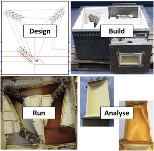
An EU funded R&D project, H2-IGCC, has been investigating different specific aspects of such an IGCC system in terms of: (a) materials performances; (b) H2 rich syngas combustion; (c) turbo-machinery design and (d) alternative cycle configurations.Citation19 As part of the materials performance research for this project it was necessary to exposure potential materials systems for blades/vanes to more realistic operating environments than possible in laboratory furnaces. The use of a cascade on a burner rig offers a cost-effective route to achieving this, and also has the benefit of enabling component manufacturing processes, including coating application methods, to be demonstrated as part of the activity.
As part of the European COST522 and 538 programmes (that had research activities targeted at the standardisation of test and assessment methods for gas turbine materials),Citation3,Citation7 a series of six burner rigs were used to investigate gas turbine materials performance.Citation3 Each of those rigs had different unique operating characteristics, with rig designs ranging from those that operate with realistic combustion gas stream temperatures and flows, and samples cooled to typical real world component operating temperatures, to those rigs that operate isothermally with very low combusted gas flows.Citation21,Citation22 For the purposes of the H2-IGCC research project it was decided to adapt one of these burner rigs by fitting it with a cascade of air-cooled blades. The advantage of exposing the blades in this way, rather than in a system with slow flowing or static gases, is that realistic interactions between the gas stream and blades can take place as the gas flows around the aerofoil shapes. In addition, air cooling of the blades can be carried out that can permit the condensation of various volatile, potentially corrosive species, as happens in operating gas turbines.
This paper is focused on describing the design and development of a novel burner rig cascade system for the H2-IGCC project. In addition, it outlines the initial experimental work carried out using this modified rig and gives examples of the materials damage experienced during these trials to illustrate that realistic gas turbine environments have been achieved. Detailed results of the extensive materials assessment studies carried out on the cascade blades (using both non-destructive and destructive examination methods) are beyond the scope of the paper and will be reported separately.Citation23
Burner rig cascade design, development and construction
The burner rig selected for this activity was a natural gas fired, atmospheric pressure modular ducted unit that has previously been used to exposure air-cooled cylindrical test samples. The original configuration of this rig had a maximum rating of 1.4 MWthCitation21,Citation24 with a maximum combusted gas temperature of 1400°C, but this was modified about 5 years ago to enable a maximum combusted gas temperature of 1600°C with a 0.7 MWth combustor and a pre-heated combustion air stream. Figure a shows a schematic diagram of the later of these rig configurations.
2 Schematic diagrams of the burner rig designed to simulate IGT combustion conditions using a cylindrical air-cooled samples and b after modification to include a cascade of air-cooled blades

The further modification of this rig with the incorporation of a cascade of turbine blades is described in the following sections.
Cascade design
The cascade design had many practical limitations as a result of the burner rig that had been selected for its installation and the blades that had to be used in its operation.
The limitations arising from the burner rig included:
A combustor with a maximum rating of 0.7 MWth.
A maximum test section length of 1.2 m, imposed by the separation between the combustor exit and exhaust chamber inlet.
A maximum pressure drop across the cascade (140 mbar), imposed by the supply pressure of the natural gas.
Air cooling for the blades limited by the supply from the two existing air compressors: a Boge S50 capable of delivering 6.35 m3 min−1 and a Compair L45 capable of delivering between 1.48 and 7.95 m3 min−1.
The blades that had to be used in the cascade were from a Siemens’ V64.3 gas turbine. The size of the blades in terms of their height and width determined the combusted gas flow required per blade. This was one factor in determining the number of blades possible within each stage of the cascade. Another factor was the need to consider edge effects. Within each cascade stage, the two blades in contact with the cascade wall (positioned such that only one of their long faces (pressure or suction) would be exposed to the hot gas path) would see significant edge effects in the hot gas path. Only the blades between these ‘wall’ blades would see gas flows comparable to those in engine operation. In addition, the total number of blades available for the set-up, commissioning and initial trial was limited by their supply. As a result, it was decided that the blades would be exposed in the cascade in three stages of five blades each; allowing three blades per stage to experience ‘realistic’ gas flows on both pressure and suction sides. Figure b illustrates the burner rig with cascade schematic.
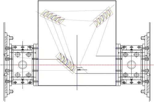
The geometry of the blades dictated the deflection of the gas stream and the angles that needed to be used between of the cascade stages. Thus, several issues needed to be considered to design the gas path for the cascade ():
The staggering of the blades in each stage;
The angle(s) through which the hot gas would be deflected;
The difference in gas path width between entering and exiting each stage;
The mixing distance of the main combustion gas flow with the cooling air that would exit from the blade trailing edges so that the next stage of the cascade could be positioned far enough downstream to avoid ‘cool spots’.
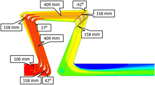
3 Blade geometries determined the angles blades were mounted at in the cascade; three blades per cascade stage were in the centre of the combusted gas stream and the remaining two blades were integrated into the gas stream containment wall
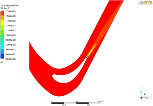
In order to carry out these calculations a computational fluid dynamic (CFD) model of the cascade was created using ANSYS-FLUENT. This included details of the blade aerofoil designs and also incorporated the various limitations on the gas path as outlined above. Calculations of potential gas flows were conducted based on meshes generated in CFX 14 solver and Centaur. The gas was assumed to be ideal and compressible, and Menter SST was used to model turbulence. It should be noted that to direct the gas path through the cascade in the required zigzag manner, two blade stages needed to be orientated ‘upside down’ relative to the other. This ensured that the gas flows could be deflected so that the inlet and final exit flows had the same centre line (and thus could use the existing burner rig configuration).
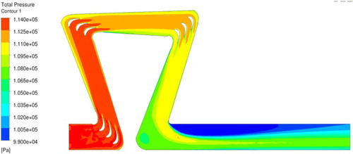
One key output from this analysis was to confirm the pressure drop throughout the cascade. The modelling work confirmed that this pressure drop was less than 140 mbar (); the natural gas supply pressure. This ensured that sufficient natural gas flow would take place to enable stable burner operation. Another key output was confirm that cooling air from the trailing edge of the blades mixed well with the combustion gas stream before it arrived at the next cassette ().
4 Results of CFD calculations of combustion gas stream pressure drops throughout the cascade
5 Results of CFD calculations show that the cooling air leaving the trailing edge of a cascade blade mixes well with the general hot gas flow before it interacts with the next cascade stage
Based on these gas path calculations, a series of engineering drawings for the cascade were produced (e.g. general assembly shown in ). The blades were mounted such that the central 60 mm of the blade would be exposed to the hot gas path. The blade’s firtree root and platform would be below the hot gas path, while the shroud and knife edges would be above this hot gas path; this would allow cooling air entry and partial exit systems to be engineered (Section ‘Adapting blades for use in the cascade’).
6 General assembly drawing of the overall cascade system showing the positions of the three cascade stages, position of the hot gas path for the combusted gases, as well as the cascade hot gas inlet (left side) and exit (right side)
The overall cascade design had an inlet to outlet (not gas path) length of 728 mm. This was 472 mm less than the existing burner rig’s combustion chamber to exhaust chamber gap. As such, two bridging sections were integrated into the design. These had the additional advantage of allowing space to bolt the new cascade test section in to the gap and also space to connect the air cooling required for the blades.
Adapting blades for use in the cascade
The Siemens’ V64.3 gas turbine blades used in the cascade are designed to operate with air cooling to maintain the aerofoil surfaces in contact with the hot combusted gas stream within a target operational temperature range. To ensure that the correct surface temperatures were maintained for the blades while in the cascade it was necessary to supply cooling air separately to each blade. This individual cooling air feed approach was adopted since there was a concern that small pressure differences between blades in the near atmospheric pressure combustion gas flow path might prevent equal cooling for all blades if the cooling air was just supplied to the each cascade stage (i.e. groups of five blades). The CFD flow path modelling and other design information from Siemens confirmed that the existing compressors were able to meet the cooling air demand from the 15 blades in the cascade.
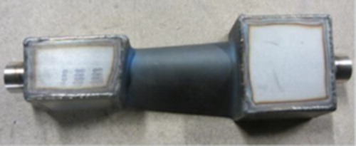
When this particular blade design is used in gas turbine operation, the cooling air is supplied through feedholes in the firtree root and then exits into the combustion gas stream either through the trailing edge or via holes above the blade shroud. Thus, connections were required to the blade roots and tips to handle the cooling air inlet and partial exit flows, respectively. As both of these parts of the blades have complex geometries, it was decided to avoid joining with either of these directly by instead welding boxes onto the blade platforms and shrouds, and so fully encase the air inlets and outlets (). The design of the cascade meant that these cooling air handling boxes for each blade were positioned well outside the combustion gas flow paths. The cooling air inlet pipes leading to each blade entered through holes in the cascade’s containment box. However, due to its elevated temperature, the heated cooling air exiting the blade tips was piped away until it could be vented into the main cascade combusted gas path close to the overall cascade exhaust. All of these air handling boxes were manufactured from Hastelloy X sheet and alloy 625 weld filler to ensure that they withstood the cascade’s operational temperatures.
7 The boxes fitted the blade root and shroud to the blades’ modified cooling air supply and partial exit, respectively. The blade root (cooling air inlet) is to the right. The blade shroud (main cooling air exit) is to the left
For ease of handling it was decided to join together the sets of five blades that made up each of the cascade stages into cassettes. This was carried out by welding strips of Hastelloy X across the cooling air inlet and outlet boxes on each of the sets of five blades.
Cascade construction and instrumentation
The cascade was housed in a welded mild steel containment box, with a water-cooled jacket to prevent it from overheating. This box was fully lined with layers of Microtherm insulation to reduce the heat transfer from the main combustion gas path to the containment box, and so maintain the required gas temperature within the cascade.
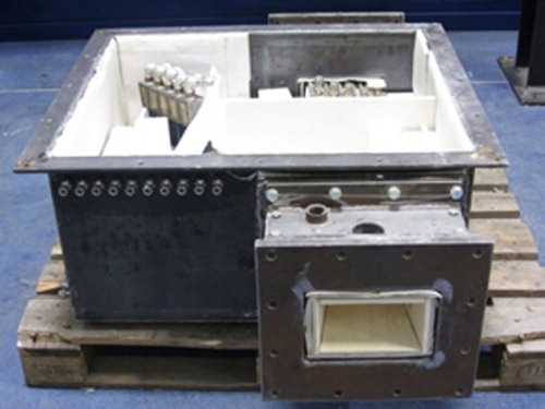
Following the cascade design (Section ‘Cascade design’), the cascade hot gas path was lined using a double layer of 10 mm thick dense cordierite tiles, cut to size and supported on insulating refractory blocks (with any gaps between the blocks filled by silica sand). The refractory blocks were positioned so that the AISI 316L stainless steel pipes used for the blade air cooling supply and hot air removal could be grouped together for each cassette of blades. Figure shows the cascade construction midway through assembly.
8 Photograph of cascade midway through its construction. The cascade inlet is at the front right, and outlet at the back. In the top left, the third and final stage of cascade blades can be seen
The combined burner rig and cascade includes instrumentation for data logging as well as measurements made to control the system during periods of automated operation including:
Combustion air and natural gas flow rates and temperature measurements;
Monitoring of pressures in the combustion chamber, in the cascade and in the combustion gas exhaust chamber;
Temperature measurements of the combusted gas stream in the combustor, ahead of each stage of the cascade, after the cascade and in the exhaust gas stream (using R-type thermocouples);
Temperature measurements of the cooling air entry and exit temperatures for each of the blades (using K-type thermocouples on each of the air lines);
Cooling air pressure control and cooling air flow rates for each of the blades;
Composition of composition gas steam before and after the cascade (using an ADC MGA 3000 series multi-gas analysis system for CO2, O2, CO and SO2);
Data were logged using a National Instruments CompactRIO data logging system.
Cascade blade materials
The blades were all manufactured from Rene 80, a nickel-based superalloy with a nominal composition of 14 wt-% Cr – 9.5% Co – 5% Ti – 4% W – 3% Al – 4% Mo – 0.16% C – 0.015% B – 0.03% Zr – balance Ni. All of the blades were coated. One set of blades had a corrosion-resistant metallic coating (Sicoat 2464) applied to it using a high velocity oxyfuel (HVOF) system. Another set of blades had a selection of four thermal barrier coating and bond coating combinations applied to it (, which are the subject of a separate paper),Citation23 but included a reference coating system of air plasma sprayed 8 wt-% yttria – stabilised zirconia ceramic on a Sicoat 2462 HVOF bond coating.
9 Four different TBC coating systems (ceramic and bond coat combinations, indicated by different colours) were applied to blades in the centre of each cascade stage. The blades that formed the cascade walls in each cascade stage (shown in black-and-white) were coated with just the metallic corrosion-resistant coating Sicoat 2464

Pre-exposure the blades with the TBCs were assessed by non-destructive analysis techniques (photography, flash thermography and F-SECT) to gather baseline data. Post-exposure, the blades were removed from the cascade and analysed by both non-destructive and destructive techniques (optical microscopy and scanning electron microscopy (backscattered electron imaging) with energy dispersive X-ray analysis; SEM/EDX) to identify the damage mechanisms that had been operating. To compare exposed and unexposed samples, reference blades for each of the coating systems were produced and analysed. Detailed results from this materials study are being reported elsewhere.Citation23
Cascade operation
Two periods of cascade operation have been carried out: the first was a commission run of 300 h using metallic coated blades in all positions within the cascade, while the second was a longer initial trial of 1000 h using TBC coated blades in the three central positions of each cascade stage ().
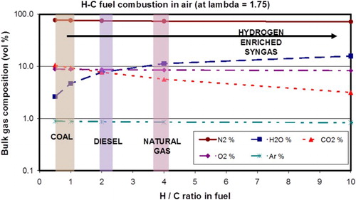
Both of these periods of operation used the same target simulated combusted flue gas composition. This was calculated using a mass balance technique for different hydrocarbons and assumed lambda values in the range 1.75–2 (1.75 example given in ). To generate the required gas composition, natural gas was combusted in the burner rig (b) and deionised water injected (at a rate of 1 L every 3 min) alongside the flame into the combustion chamber to increase the concentration of H2O in the hot, combusted gas stream.
10 Calculated concentrations of species expected for different fuels (defined by their hydrogen to carbon ratio) assuming combustion where lambda is 1.75
For both periods of operation the following test parameters were chosen:
Gas stream temperature exiting the combustion chamber: 1440°C.
Gas stream temperature at the three cascade states: from ∼1340 (at cascade inlet) to ∼1100°C (at cascade outlet).
Estimated temperatures of the blades: controlled with air-cooling system to maintain bond coat surface temperatures of 950–1050°C (depending on location in cascade).
Flue gas composition based on combusted natural gas but with the H2O level boosted to ∼20 vol.-% to simulate combusted H2-rich syngas.
Results and discussion
Cascade commissioning run
The newly modified burner rig and cascade system was successfully run for 300 h with combustion temperatures of up to 1440°C (first cascade stage gas temperature of up to 1340°C) in both manual and automated control modes. All of the blades exposed in this run were Rene 80 coated with a metallic corrosion-resistant coating (Sicoat 2464), which were used just to prove the viability of the new modified rig system.
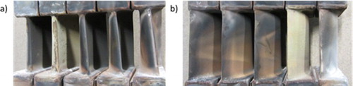
As shown in , one of the blades (coloured white) overheated. This was found to be as a result of a fault in the cooling air supply pipework leading to that blade; this fault was corrected before the main cascade test run. In addition to this, flow-marks can be observed in the deposits formed on the five blades from this example (using cascade stage 2). These markings are comparable to those observed on aerofoils in IGTs.Citation25
11 Photographs taken of the a leading and b trailing edges of blades exposed in the second stage of the cascade after its removal following the 300 h cascade/modified burner rig commissioning run. Note the presence of one ‘white’ blade that had over-heated due to a faulty cooling air supply system
Cascade 1000 h trial operation
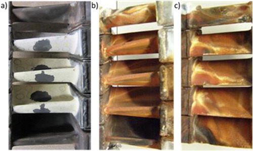
Following the successful completion of the commissioning run, the test TBC coated blades were substituted into the cassettes and the cascade re-built. Figure shows one of these blade cassettes pre- and post-exposure (from cascade stage 1). All of the new TBC coated test blades initially appear white/cream (as expected for these unexposed coatings) while the metallic coated wall blades (previously exposed in the commissioning run) are grey/brown. The black marks and circles on the unexposed TBCs are carbon paint from the coatings’ pre-exposure non-destructive analysis (Section ‘Cascade blade materials’). The carbon paint is not believed to be detrimental to the performance of these coating systems.Citation23 Post-exposure, the TBCs appeared to have more red/brown colouration due to the presence of Fe-rich deposits.
12 Cassette of blades from the first cascade stage of the initial 1000 h trial showing: a leading edge pre-exposure, b leading edge post-exposure and c trailing edge post-exposure
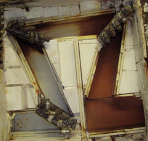
These deposits were also found on some of the ceramic tiles that had been used to line the cascade hot gas path (). Data from the gas path thermocouples indicates that these red/brown deposits had precipitated out at temperatures between ∼1250 and ∼1100°C. MTData thermodynamic stability calculations run with iron concentrations of the order of 10s of parts per billion, indicate that gaseous iron oxides/hydroxides present at the higher gas temperatures can react to form condensed oxides below ∼1100–1200°C.
13 Photograph of the cascade gas path after the 1000 h trial showing the development of red/brown discolouration between the second and third cascade stages
Example post-exposure reference blade analysis
Destructive analysis of example reference blades after their 1000 h exposure revealed several damage mechanisms present in different areas of the blade aerofoils. Some of the blades revealed TBC loss at the leading edge ( and ). There are several possible explanations for this. The coating could have undergone erosion; the coating manufacturing may have had imperfections; or oxidation/hot corrosion of the bond coat could have caused delamination.
14 (left) Erosion of TBC coating can be visually observed on the leading edge of some blades post-exposure. (right) SEM/EDX data shows hot corrosion following the loss of part of a TBC. Cross-section taken at 50% of blade height
15 Some blades showed extensive cracking and delamination of the TBC post-exposure. Cross-section taken at 50% of blade height
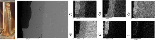
Where the TBC had delaminated, hot corrosion could be observed (). Hot corrosion was also observed under cracked, but still present, TBC layers (). The presence of hot corrosion indicates that expected alkali deposits have condensed from the combusted hot gas stream and onto the air-cooled blades.
16 SEM/EDX mapping images show the presence of oxidation and hot corrosion post-exposure. Cross-section taken at 50% of blade height
Conclusions
As part of the EU H2-IGCC project it has been necessary to demonstrate the suitability of state-of-the-art gas turbine blade/vane materials in the novel operating environments anticipated for a gas turbine burning H2-rich syngases (following pre-combustion CO2 capture).
To enable this work to be carried out, a cascade using air-cooled IGT blades has been designed for incorporation into an existing burner rig. This cascade design was developed and optimised using a CFD model of the cascade that took into account the various limitations imposed by using an existing burner rig and existing gas turbine blades. The final design cascade design had three stages each with five blades, the outer two of which formed parts of the hot gas path walls.
This cascade was built and installed into the burning rig, before being operated for 300 h as part of its commissioning process. The rig used combusted natural gas with extra water injected to generate the desired combustion environment for simulating the use of a H2-rich syngas. The cascade gas temperature just upstream of the first stage was to 1340°C.
The cascade was then re-built using TBC coated blades in the central three positions in each cascade stage. This configuration was operated for 1000 h using the same combusted gas environment as for the commissioning process.
After these exposures, initial examinations of example blades showed that a range of degradation mechanisms including hot corrosion, erosion and coating delamination had been experienced. More detailed examinations of these materials systems will be reported elsewhere.
The development of this cascade/burner rig has provided a facility that will help characterise and understand the various potential failure mechanisms of advanced and state-of-the-art coating systems in novel combustion environments.
Acknowledgements
The authors would like to thank B. Carpenter, P. West, E Hakon and A Potter for their work in constructing the cascade and operating the modified burner rig/cascade system. This work was supported by the Seventh Framework Programme through Grant number FP7-239349.
References
- European Commission: ‘Communication from the Commission to the European Parliament, the Council, the European Economic and Social Committee and the Committee of the Regions: A Roadmap for Moving to a Competitive Low Carbon Economy in 2050’, Report: COM/2011/0112 final, European Commission, 2011.
- P. Dechamps: ‘The EU research strategy towards zero emission fossil fuel power plant’ in ‘Materials for power engineering 2006’, (eds. J. Lecomte-Beckers et al.), Part 1, 25–36; 2006, Jülich, Forschungszentrum Jülich.
- N. J. Simms, J. Sumner, T. Hussain and J. E. Oakey: ‘Fireside issues in advanced power generation systems’, Mater. Sci. Technol., 2013, 29 (7), 804–812. doi: 10.1179/1743284712Y.0000000133
- B. Waschbüsch and H-P. Bossmann: ‘Influence of the salt composition on the hot corrosion behaviour of gas turbine materials’ in ‘Lifetime modelling of high temperature corrosion processes’, (eds. M. Schütze et al.), EFC No. 34, 261–273; 2001, Houston, TX, Nace.
- GE Power Generation: https://powergen.gepower.com/products/heavy-duty-gas-turbines.html (accessed 26/2/2017).
- Siemens Gas Turbines: http://www.energy.siemens.com/hq/en/fossil-power-generation/gas-turbines/ (accessed 26/2/2017).
- D. H. Allen, J. E. Oakey and B. Scarlin. ‘The new cost action 522 – power generation in the 21st century: ultra efficient, low emission plant’ in ‘Materials for advanced power engineering 1998’, (eds. J. Lecomte-Beckers et al.), 1825–1838; 1998, Jülich, Forschungszentrum Jülich.
- S. T. Scheirer and R. Viswanathan: ‘Evolution of Hot Section Materials Technology’, Proc. ASM Materials Solution Conf., St Louis, MO, USA, October 2000, ASM International.
- T. Schulenberg: ‘New development in land-based gas turbine technology’ in ‘Materials for advanced power engineering 1998’, (eds. J. Lecomte-Beckers et al.), 1825–1838; 1998, Jülich, Forschungszentrum Jülich.
- N. J. Simms, D. W. Bale, D. Baxter and J. E. Oakey: ‘Environmental degradation of gas turbine coatings: towards standardised testing and databases’ in ‘Materials for advanced power engineering 2002’, (eds. J. Locomte-Beckers et al.), 73–88; 2002, Jülich, Forschungszentrum Jülich.
- C. T. Sims, N. S. Stoloff, and W. C. Hagel: ‘Superalloys II’; 1987, New York, NY, Wiley.
- R. C. Reed: ‘The superalloys – fundamentals and applications’; 2006, Cambridge, Cambridge University Press.
- J. R. Nicholls and R. Wing: ‘Advances in coating systems for utility gas turbines’ in ‘Materials for advanced power engineering 2002’, (eds. J. Locomte-Beckers et al.), 57–71; 2002, Jülich, Forschungszentrum Jülich.
- R. Vassen, M. O. Jarligo, T. Steinke, D. E. Mack and D. Stöver: ‘Overview on advanced thermal barrier coatings’, Surf. Coat. Technol., 2010, 205, 938–942. doi: 10.1016/j.surfcoat.2010.08.151
- H. Singh, B. S. Sidhu, D. Puri and S. Prakash: ‘Use of plasma spray technology for deposition of high temperature oxidation/corrosion resistance coatings – a review’, Mater. Corros., 2007, 58, (2), 92–102. doi: 10.1002/maco.200603985
- N. Birks, G. H. Meier and F. S. Pettit: ‘Introduction to the high-temperature oxidation of metals’, 2nd edn; 2006, Cambridge, Cambridge University Press.
- O. Maurstad: ‘An overview of coal based integrated gasification combined cycle (IGCC) technology’, Technical publication, MIT LFEE 2005-002 WP; 2005, MA, USA, Massachusetts Institute of Technology.
- C. C. Cormos: ‘Assessment of hydrogen and electricity co-production schemes based on gasification process with carbon capture and storage’, Int J Hydrogen Energy, 2009, 34, 6065–6077. doi: 10.1016/j.ijhydene.2009.05.054
- H2-IGCC project homepage: http://www.h2-igcc.eu/ (accessed 11th January 2017).
- J. Sumner, A. Potter, N. J. Simms and J. E. Oakey: ‘Hot corrosion resistance of gas turbine materials in combusted syngas environments’, Mater. High Temp., 2015, 32(1–2), 177–187. doi: 10.1179/0960340914Z.00000000098
- N.J. Simms, J.R. Nicholls and J.E. Oakey, ‘Materials for solid fuel fired gas turbines: burner rig and laboratory studies’, Mater. Sci. Forum., 2001, 369–372, 833–840. doi: 10.4028/www.scientific.net/MSF.369-372.833
- J. R. Nicholls and S. R. J. Saunders: ‘Hot-salt corrosion standards, test procedures and performance’, High Temp. Technol., 1989, 7, (4), 170. doi: 10.1080/02619180.1989.11753433
- J. Sumner, D. E. Mack, F. Cernuschi, W. Stamm, A. Moscatelli, S. Nardone, B. Sarens, N. J. Simms and J. E. Oakey, ‘Advanced Coatings for Novel Combustion Environments in Gas Turbines Fired on H2-Rich Syngas’, in preparation.
- J. Sumner, A. Encinas-Oropesa, N. J. Simms and J. E. Oakey: ‘High temperature oxidation and corrosion of gas turbine materials in burner rig exposures’, Mater. Sci. Technol., 2013, 29, (7), 813–821. doi: 10.1179/1743284712Y.0000000097
- A. G. Stamatis: ‘Engine condition monitoring and diagnostics’ in ‘Progress in gas turbine performance’, (ed. E. Benini), 187–212; 2013, Rijeka, Croatia, InTech.