
ABSTRACT
A novel, low-alloy steel has been designed for use in the oil and gas industry. Its high strength and hydrogen trapping potential are derived from a martensitic microstructure containing a dispersion of fine vanadium–molybdenum alloy carbides that evolve during tempering. In this second paper, the effect of quench rate from austenitisation and tempering conditions are investigated with respect to the microstructure. The alloy loses its tempering resistance following slow-cooling from austenitisation as a result of MC precipitation, leading to vanadium depletion and significant MC coarsening. This is predicted using computer simulation and confirmed by high energy X-ray diffraction, combined with electron microscopy.
Introduction
High-strength steel is required to exploit subsea oil and gas reserves that operate at an elevated temperature and pressure. However, high-strength steel exacerbates the susceptibility to hydrogen embrittlement [Citation1–5]. This is especially problematic with a hard microstructure, thermally induced residual stresses and a constant supply of hydrogen that is generated during the service life of the material. For this reason, a quench and tempered steel containing alloy carbide precipitates has been designed, that is capable of trapping diffusible hydrogen and rendering it harmless. Full details are available in Part 1 [Citation6], which includes the mechanical properties and hydrogen trapping capacity when compared with a commercially available F22 grade steel.
In the new alloy, designated HT10, a fine dispersion of V–Mo–Cr carbides throughout the martensite provide the mechanism for both strengthening and hydrogen trapping [Citation6]. These precipitates must be sufficiently small to remain coherent with the surrounding matrix and produce the strain fields [Citation7] necessary to act as trap sites [Citation8–11]. The V–Mo–Cr carbides that form in HT10 are expected to be non-stoichiometric and carbon deficient [Citation12–14], containing up to 30 wt-%Mo [Citation15]. It has been shown that the morphology of the carbide is spherical in nature if formed during austenitisation and is in fine platelet form when precipitated during tempering [Citation6]. Because the alloy undergoes a series of thermal cycles during manufacture, its precipitation behaviour has to be known to ensure the correct particle size and distribution that provide adequate level of hydrogen trapping capacity. This paper investigates the effect of the cooling rate from austenitisation along with tempering conditions and their combined influence on the alloy carbide precipitate evolution.
Experimental procedure
An experimental casting of HT10 was produced by vacuum induction and hot rolled to achieve a forging reduction ratio of 4.5:1. The measured chemical compositions of HT10, along with F22, are in Table . The phase transformation temperatures and prior austenite grain size (PAGS) were measured following a solution treatment at 1050C for 0.5 h. The PAGS were determined using the linear intercept method and transmission electron microscopy (TEM) was conducted on electro-polished foils with an FEI TECNAI Osiris operating at 200 kV. The chemical composition of the precipitates was determined by energy dispersive spectroscopy (EDS).
Table 1. Measured compositions (in wt-%), phase transformation temperatures and PAGS.
Effect of cooling rate on tempering hardness
Specimens were prepared from the as-received hot-rolled plate and austenitised at 1050C for 0.5 h to dissolve most of the carbides that may have formed. Cooling rates of 3400, 120 and 60
C h−1 were adopted, followed by tempering at 600
C for various times. The hardness profiles as a function cooling condition (Figure ) suggest that HT10 has a high degree of hardenability, which is necessary when manufacturing thick sections. However, the alloy loses its tempering resistance following slower cooling from austenitisation.
Figure 1. Effect of cooling rate from austenitisation on hardness for HT10 steel tempered at 600C.
Synchrotron X-ray diffraction
Following thermal treatment, 2 mm diameter and 2.5 mm long specimens were machined for high-energy X-ray diffraction (XRD). The experiment was performed on the I12 beamline at Diamond Light Source, UK. A Debye-Scherrer geometry with sample rotation was employed to improve intensity and avoid the effects of preferential orientation. The instrument was calibrated against a cerium dioxide standard and the X-ray wavelength was 0.1559 Å. The data were analysed with Materials Analysis Using Diffraction (MAUD) [Citation16] software, which was used to calculate the retained austenite content and lattice parameters. The carbon concentration of the austenite was then estimated from the lattice parameter, Onink et al. [Citation17]. The martensite dislocation density was evaluated using the approach detailed by Williamson et al. [Citation18,Citation19].
Synchrotron XRD data were analysed using Rietveld refinement [Citation20,Citation21]. No stable fits with carbides were possible due to their minimal volume fractions, therefore, only austenite and martensite were included. The following variables were included in the refinement: the background function (fifth-order polynomial), incident X-ray intensity, austenite phase fraction, lattice parameter, texture (eighth-order spherical harmonics), crystallite size and microstrain for both austenite and martensite. Isotropic microstrain and crystallite size were assumed.
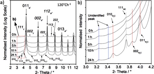
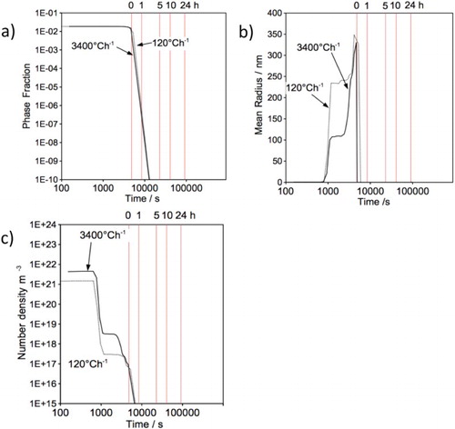
Figures (a) and (a) present the obtained X-ray diffractograms for fast-cooled (3400C h−1) and slow-cooled (120
C h−1) samples followed by tempering at 600
C for various times. Figures (b) and (b) highlight a magnified section of the spectrum where the weaker but significant contributions from MCFootnote1 and M
CFootnote2 can be resolved. Although the peak positions of MC and M
C are the same for both fast- and slow-cooled specimens, the peak broadening behaviour is different. The MC and M
C peaks observed after fast-cooling and 24 h tempering are shorter and broader, indicating that a smaller particle size is produced.
Figure 2. (a) X-ray diffractogram of HT10, austenitised and cooled at 3400 Ch−1; (b) magnified section of (a).
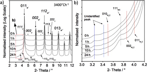
Figure 3. (a) X-ray diffractogram of HT10, austenitised and cooled at 120 Ch−1; (b) magnified section of (a).
Retained austenite is detected in the untempered condition for both cooling rates but it is not present following tempering for 1 h. It is expected that retained austenite would transform to ferrite and cementite during reheating and tempering. During reheating and tempering, cementite is expected to form first from supersaturated martensite, cementite would then dissolve and form alloy carbide during further tempering at 600C indicated by the increase in intensity of the MC and M
C peaks. A very small austenite (
) peak remains after tempering for 1 h and the peak increases in size as the tempering time progress. This is due to the precipitation of nickel-rich austenite (
) as reported in nickel-added steel [Citation22–24].
Figure highlights the effect of cooling rate from austenitisation and tempering time on the martensite (b) lattice parameter, (c) tetragonality and (d) dislocation density. Figure (a) provides an indication of the goodness-of-fit for the data refinement, evaluated using the weighted profile R-factor (), where a lower value corresponds with improved fitting. The
increases with tempering time due to higher carbide contents, that were not included in the Rietveld analysis.
Figure 4. (a) Weighted profile R-factor ; (b) lattice parameter; (c) tetragonality; (d) dislocation density.
The martensite loses its tetragonality (ratio of the lattice parameters, c/a) with prolonged tempering times and tends towards a cubic structure as carbon vacates the interstitial sites [Citation25,Citation26]. Both fast- and slow-cooling resulted in similar hardnesses, despite lower dislocation density in the latter (Figure (d)). Samples cooled at both rates show a gradual reduction in dislocation density with increased tempering time.
A larger austenite lattice parameter is observed in the slow-cooled specimen (Figure ), which is consistent with the extended time allowed for carbon to partition into the austenite during martensitic transformation [Citation27].
Figure 5. (a) Lattice parameter and calculated carbon content of austenite for untempered HT10 steel.
The phases identified by synchrotron XRD are listed in Table , along with the measured unit cell using the stated space group. The unit cells of MC and MC were calculated from the measured d-spacing at [111]
,
and
reflection, respectively. The lattice parameters of the molybdenum-rich carbides (M
C) are very close to the reported values [Citation28,Citation29]. The measured lattice parameter of MC in this work is comparable to some literature values [Citation30–32], whilst there are slight differences (but less than 0.6%) when compared to other data [Citation7]. There is no evidence from the obtained synchrotron XRD spectra that the monoclinic V
C
[Citation13] is formed.
Table 2. Space group and measured unit cell of the phases identified with synchrotron XRD.
Precipitate characterisation with TEM
Microstructural characterisation in Part 1 identified fine V–Mo–Cr-rich carbides distributed throughout a martensitic matrix for rapidly cooled and tempered HT10 steel. In this work, additional precipitates are observed and distinguished in terms of their structure, shape and composition. When subjected to slow-cooling from austenitisation (1050C), a martensite lath matrix is still observed, Figure (a), indicating low carbon content in austenite before martensite transformation. However, the partition of carbon is also evident, where Figure shows a high carbon content in the retained austenite in slow-cooling steel. The evident is further supported by the detection of twin martensite in Figure (b), which is commonly associated with high-carbon martensite transformation.
Figure 6. Microstructures following slow-cooling (120 Ch−1); (a) lath martensite matrix, (b) twin martensite.
The carbide species can be characterised by the diffraction pattern and the measured Mo/V ratio using EDS. The expected element weight ratio of both MC and MC at 600
C were calculated using the precipitate kinetic module within Matcalc, Table . In order to incorporate the material surrounding the precipitates within the interaction volume, the carbide weight ratio was multiplied by that of the matrixFootnote3. In this work, a precipitate is considered to be an MC carbide if the Mo/V weight ratio is
. M
C type carbides are defined by a Mo/V ratio between 7 and 16. The chemical compositions of the identified precipitates based on the discussed Mo/V ratio criteria were shown in Table .
Table 3. Element weight ratios at 600 C calculated using precipitate kinetic module within Matcalc.
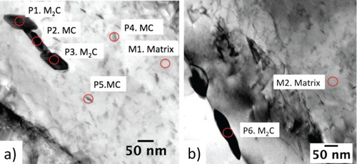
Table 4. Chemical composition of the precipitates and matrix identified in Figure . The sample was slow-cooled from austenitisation and tempering at 600C for 24 h.
As in Part 1, MC carbide precipitation within the martensite laths were also been detected, Figure shows a fine MC carbide that possesses a Baker and Nutting orientation relationships within a martensite lath in a high-resolution transmission electron microscopy (HRTEM) image. Large MC precipitates were also observed at pre-existing MC sites, following tempering at 600
C for 24 h. Such M
C particles nucleation nature has been reported in the literature [Citation15,Citation33,Citation34] and is identified by the characteristic ‘H’ morphology. The local depletion of vanadium following MC precipitation and replenishment with molybdenum from the solid solution leads to such precipitation phenomenon. Elongated M
C particles can also form at the grain and martensite lath boundaries (e.g. P6 in Figure (b)).
Figure 7. Small MC precipitate observed after slow-cooling from 1050C and tempering at 600
C for 24 h; (a) HRTEM image (b) FFT diffractogram of (a) showing that the alloy carbide possesses Baker and Nutting orientation relationships with martensite lath.
Figure 8. Slow-cooling and tempering at 600C for 24 h produces large M
C precipitates; (a) on an existing MC particle with fine carbides in the martensite lath, (b) at grain/lath boundaries.
The measured Cr/Mo ratio of both MC and MC were also included in Table . Comparing the EDS measured and calculated values, it is evident that larger amount of Cr partition into both MC and M
C than has been reported by others [Citation12,Citation35,Citation36].
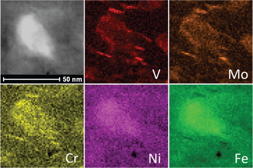
TEM micrographs shown in Figure reveal the austenite () identified during synchrotron XRD, which is enriched in Cr, Ni and Fe. In this figure, fine V–Mo–Cr-rich carbides were found in the surrounding of a larger precipitated austenite (
).
Figure 9. Fast-cooled sample, tempered at 600C for 10 h. Cr, Ni, Fe-rich precipitates with some V, Mo, Cr carbide. The Cr, Ni, Fe-rich precipitation is austenite (
), while V, Mo, Cr-rich precipitate is carbide.
MC, MC and precipitated austenite (
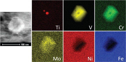
) were all identified using TEM/EDS mapping. These observations correlate with the phases recorded during synchrotron XRD. Other large particles identified in very low concentrations consisted of a Ti-enriched core surrounded by a V–Mo–Cr carbide shell, Figure . Ti-rich precipitates that formed during casting and reheating before hot rolling remain undissolved at the high austenitisation temperature, while the V–Mo–Cr carbide shell would form preferentially on the Ti-enrich core at lower temperature during slow cooling. Epitaxial precipitation is common in Ti-V containing steel and its formation mechanism is explained elsewhere [Citation37].
Figure 10. Ti-rich particle encapsulated by V, Mo and Cr following slow-cooling (120C h−1).
Thermo-kinetic simulation
The precipitation kinetics, during heat treatment cycles, were determined using MatCalc version 5.52, release 1.002. The theoretical concepts are reported in the literature [Citation38–40]. The simulation parameters (Table ) follow the work performed by Zamberger et al. [Citation41,Citation42] and were obtained from the metallographic and synchrotron diffraction work in the previous section, also included are the precipitate phases, their major constituents, shape factor and nucleation composition. Precipitates can nucleate at a variety of microstructural features but dislocations inherited from martensitic transformation are considered to be the primary nucleation sites for both MC and MC [Citation43]. Grain boundaries, subgrain boundaries and dislocation are judged to be the nucleation sites for M
C, based on TEM observation.
Table 5. Summary of the microstructural parameters used for the simulation.
Results for the numerical simulations are based on the thermal treatment in Figure . Cooling from 1200C is used to simulate high-temperature precipitation that may typically form during casting and hot rolling. Austenitisation is performed at 1050
C for 0.5 h, which is sufficiently high to dissolve the majority of MC carbides. Two cooling rates were applied (3400 and 120
C h−1), followed by tempering at 600
C for a maximum of 24 h.
Figure 11. (a) Heat treatment cycle used for the simulation. (b–d) Precipitation kinetic in austenite during cooling from austenitisation; (b) phase fraction, (c) mean radius and (d) number density.
The effect of cooling rate from austenitisation, on the precipitation as a function of temperature, is presented in Figure (b)–(d). Due to its stability and the fact that all nitrogen has been tied up by titanium, the phase fraction and mean radius of MN are not influenced by the cooling rate. However, the phase fraction and mean radius of MC carbide increases with decreasing temperature (down to 800C) during slow cooling. Different cooling rates are not expected to alter the precipitate nucleation site and hence the number density should remain constant for both MN and MC, Figure (d).
Precipitation of MC at high temperature, when slow-cooled, will consume the carbide-forming elements in solution and alter the precipitation kinetic during tempering. The martensite compositions, before and after tempering, for different cooling rates are compared in Table . Slow cooling reduces the original vanadium bulk content from 0.44 to 0.429 wt-%, while fast cooling to 0.439 wt-%, which is an insignificant reduction. Furthermore, the calculated molybdenum matrix concentration is inconsistent with the TEM observations where it has been shown that molybdenum and chromium participate in the precipitation of MC at high temperature Figure . MC precipitation during cooling would reduce the vanadium and molybdenum concentration thus altering the Mo/V ratio in the matrix before tempering.
Table 6. Element concentrations in martensite before and after tempering.
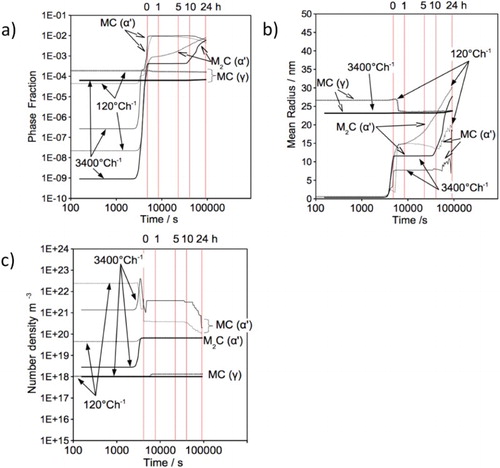
Figure shows the precipitation kinetics in martensite during cooling from austenite. The simulation assumed that the martensite transformation occurred completely at the start temperature, although it is athermal in nature [Citation44]. A slow-cooling rate encourages precipitation of both MC and MC, where greater phase fraction, larger precipitate size and higher number density were observed.
Figure 12. Precipitation kinetic in martensite during cooling from austenitisation; (a)–(b) phase fraction; (c)–(d) mean radius; (e)–(f) number density versus time.
The simulated tempering of HT10 steel at 600C suggests that the MC precipitate reaches its maximum phase fraction as soon as the tempering temperature is obtained (Figure ). The rapid increase in M
C phase fraction, observed in the slow-cooled condition, is caused by the higher Mo/V ratio present when tempering begins. Matcalc simulations suggest that M
C is present at equilibrium and even at the beginning of the tempering cycle, although it is not detected by synchrotron XRD.
Figure 13. Precipitation kinetic during tempering at 600C; (a) phase fraction, (b) mean radius, (c) number density versus time. Hour line markers indicate time at 600
C.
Specimens cooled at 3400C h−1 allow finer precipitates (8 nm) to stabilise when tempered for less than 10 h. Slow cooling increases the stabilised MC precipitate radius to 15 nm. Significant coarsening is observed after 10 h for both MC and M
C in the fast-cooled condition and MC in the slow-cooled condition. At this point, the carbides are expected to lose coherency with the matrix.
MC precipitates increase in radius, while decreasing their phase fraction and number densities after 10 h tempering. This indicates precipitation coarsening and dissolution. Both the radius and phase fraction increase simultaneously for the MC carbide, suggesting that it is more stable compared with MC. Ultimately, MC will be consumed by M
C following long-term tempering.
The simulation predicts that a slow-cooling rate from austenitisation increases MC formation in austenite, which promotes both MC and MC carbide precipitation (nucleation) in martensite during cooling. Coupled with the increased Mo/V ratio in the matrix, this leads to a more rapid M
C coarsening rate during tempering. Furthermore, a slow-cooling rate increases the radius and reduces the number density of MC carbide during tempering. For these reasons, HT10 is more temper resistant in the fast-cooled condition.
In order to maintain a tough yet high-strength steel, it is important that any cementite present undergoes dissolution and is replaced by the alloy carbides. Figure shows the calculated cementite precipitation kinetic during tempering. The phase fraction of cementite stabilises during reheating but drops to a very low level once the tempering temperature is achieved. No cementite peak was detected using synchrotron XRD after 1 h tempering.
Figure 14. Cementite precipitation kinetic during tempering at 600C; (a) phase fraction, (b) mean radius, (c) number density versus time. Hour line markers indicate time at 600
C.
Thermodynamic equilibrium calculation
The equilibrium phases as a function of temperature were calculated using Matcalc with the mc_fe_v2.000_prebeta_012 database as shown in Figure . MC is stable below 700
C compared with M(C, N). MnS and a small quantity of austenite appear below 400
C. For the M(C, N) phase, Ti and N are the major elements at high temperature, while V, Mo and C are present on cooling. Figure (d) shows that the austenite (
) that may be present at low temperature has a high nickel and manganese content. However, Ni, Cr and Fe are observed within the precipitated austenite (
) in the TEM work. Further work is necessary to clarify the precipitated austenite stability since the precipitate is detected during tempering at 600
C, while the thermodynamic calculation indicates that the precipitate is stable below 400
C. Likewise, the composition variation in MC, M
C and precipitated austenite (
) between experiment and calculation would also require further investigation, bearing in mind the experiment performed in this work is not in equilibrium.
Figure 15. (a) Equilibrium phase weight per cent of HT10 as a function of temperature. (b)–(d) The atomic fraction of (b) M(C,N), (c) MC, (d) austenite (
) as a function of temperature.
Discussion
The particle size, shape, number density, volume fraction, lattice parameter and composition of MC and MC carbide have been characterised using TEM, synchrotron XRD and computer modelling. This has allowed the microstructural changes that occur during tempering to be explained in this newly designed steel.
During tempering of HT10, both MC and MC (
, V, Cr, Mo) can form. Depending on the cooling rate from austenitisation, the precipitation kinetics are affected as well as the resistance to softening. Although equilibrium calculations predict that M
C carbide is more stable, it can only be identified following an extended tempering time. Furthermore, its coarsening rate is affected by the MC carbide that precipitates during cooling from austenitisation. Precipitate coarsening, together with the obtained dislocation density following cooling from austenitisation, determine the number density of MC carbide during tempering.
The large MC carbide that forms in austenite during slow cooling was identified with TEM, computer simulation and additionally by synchrotron X-rays. Careful observation of X-ray spectra indicates that the MC diffraction peak is prevalent for all tempering conditions, although the fast-cooled specimen produces a peak after a few hours at temperature. The high number density of fine MC precipitate (fast-cooled sample) is predicted using the computer simulation and confirmed by diffraction where a small, broad peak is recorded. The large MC peak observed for the slow-cooled sample after 24 h tempering is due to precipitation and coarsening, which occurs more rapidly under these conditions.
Regarding MC precipitation, which is only detected after tempering time of 24 h at 600
C, there is a discrepancy with MatCalc calculation (Figure ) which indicates earlier precipitation during tempering. However, the calculations rely on nucleation sites assumed to be dislocations, grain boundaries and subgrain boundaries. The number density of such sites should be regarded as a fitting parameter since the number of nucleation sites per unit length of dislocation or boundary is uncertain. Furthermore, it has been observed in TEM that M
C nucleate preferentially on MC precipitation, which is not modelled in Matcalc. Additionally, the early fraction of M
C in the calculation is
which could be difficult to detect experimentally. It may also be necessary to update the thermodynamic data with respect to the chemical composition of MC and M
C, where a significant amount of molybdenum and chromium has been detected in the precipitates. Similarly, the thermodynamic data on the temperature stability of precipitated austenite precipitated in nickel containing martensite is also need updated.
Conclusions
Both MC and M
The dislocation density in the martensite, following austenitisation, influences the MC precipitate number density. The fast-cooled sample yielded a precipitate density an order of magnitude higher than the slow-cooled.
The loss of tempering resistance in HT10 following slow-cooling from austenitisation is due to the low number density of MC precipitates and significant M
Acknowledgments
The authors would like to acknowledge the technical support from BP through the BP International Centre for Advanced Materials (BP-ICAM) which made this research possible. The provision of synchrotron beam time by the Diamond Light Source is also gratefully acknowledged.
Disclosure statement
No potential conflict of interest was reported by the authors.
ORCID
S. W. Ooi http://orcid.org/0000-0001-8415-0214
C. Hulme-Smith http://orcid.org/0000-0002-6339-4612
M. Drakopoulos http://orcid.org/0000-0002-6125-7497
Additional information
Funding
Notes
1 Vanadium rich carbide with face-centred cubic structure, the exact chemical composition of this carbide is not known and may vary with bulk chemical composition and heat treatment. Most commonly reported as MC
and M
C
.
2 Molybdenum-rich carbide with hexagonal structure. ‘M’ represents metal atoms which include titanium, niobium, vanadium and molybdenum.
3 Based on the damage region observed after EDS measurement in this work, the diameter of the incident beam is estimated to be 30 nm in diameter.
References
- Waid GM, Ault RT. Waid GM and Ault RT, The Development of a New High Strength Casing Steel with Improved Hydrogen Sulfide Cracking Resistance for Sour Oil and Gas Well Applications, CORROSION 79, No. 180, National Association of Corrosion Engineers, Houston, Texas; 1979. p. 3.
- Turnbull A, Griffiths A. Corrosion and cracking of weldable 13 wt-%Cr martensitic stainless steels for application in the oil and gas industry. Corros Eng Sci Techn. 2003;38(1):21–50. doi: 10.1179/147842203225001432
- Stalheim D, Barnes K, McCutcheon D. Alloy designs for high strength oil and gas transmission linepipe steels. In: Fazackerley WJ, Bordignon P, Hulka K, et al., editors. Microalloyed steels for the oil and gas industry. Warrendale (PA): TMS; 2007. p. 73–108.
- Sponseller DL, Garber R, Cox TB. Design of H2S-Resistant steels for the tubular products used in oil and gas wells. In: Interrante CG, Pressouyre GM, editors. Current solutions to Hydrogen problems in steels. Ohio: ASM; 1982. p. 200.
- Bannenberg N, Streisselberger A, Schwinn V. New steel plates for the oil and gas industry. Steel Res Int. 2007;78:185–188. doi: 10.1002/srin.200705878
- Ramjaun TI, Ooi SW, Morana R. Designing steel to resist hydrogen embrittlement. Part 1 – trapping capacity. Mater Sci Techn. 2018.
- Baker RG, Nutting J. Precipitation processes in steels. Iron and steel institute special report no. (64); 1959. p. 1–22.
- Depover T, Verbeken K. Evaluation of the effect of VC precipitates on the hydrogen induced mechanical degradation in Fe-C-V alloys. Mater Sci Eng A. 2016;675:299–313. doi: 10.1016/j.msea.2016.08.053
- Lee J, Lee T, Kwon YJ, et al. Effects of vanadium carbides on hydrogen embrittlement of tempered martensitic steel. Met Mater Int. 2016;22(3):364–372. doi: 10.1007/s12540-016-5631-7
- Depover T, Verbeken K. The detrimental effect of hydrogen at dislocations on the hydrogen embrittlement susceptibility of Fe-C-X alloys: An experimental proof of the HELP mechanism. Int J Hydrogen Energy. 2018;43(5):3050–3061. doi: 10.1016/j.ijhydene.2017.12.109
- Cheng X, Cheng X, Jiang C, et al. Hydrogen diffusion and trapping in V-microalloyed mooring chain steels. Mater Lett. 2018;213:118–121. doi: 10.1016/j.matlet.2017.11.029
- Baker RG, Nutting J. The tempering of 2.25Cr-1Mo steel after quenching and normalizing. J Iron Steel Inst. 1959;192(3):257–268.
- Epicier T, Acevedo D, Perez M. Crystallographic structure of vanadium carbide precipitates in a model Fe-C-V steel. Philos Mag. 2008;88(1):31–45. doi: 10.1080/14786430701753816
- Jack DH, Jack KH. Carbides and nitrides in steel. Mater Sci Eng. 1973;11:1–27. doi: 10.1016/0025-5416(73)90055-4
- Carruthers RB, Collins MJ. Carbide transformations in microstructurally unstable low alloy ferritic steel. Met Sci. 1983;17(3):107–110. doi: 10.1179/030634583790421050
- Lutterotti L, Matthies S, Wenk HR, et al. Combined texture and structure analysis of deformed limestone from time-of-flight neutron diffraction spectra. J Appl Phys. 1997;81:594–600. doi: 10.1063/1.364220
- Onink M, Brakman CM, Tichelaar FD. Lattice parameters of austenite and ferrite in Fe–C alloys a sfunction of carbon concentraiton and temperature. Scr Metall Mater. 1993;29(3):1011–1016. doi: 10.1016/0956-716X(93)90169-S
- Williamson GK, Smallman RE. III. Dislocation densities in some annealed and cold-worked metals from measurements on the X-ray Debye-Scherrer spectrum. Philos Mag. 1956;1:34–46. doi: 10.1080/14786435608238074
- Williamson GK, Hall WH. X-ray line broadening from filed aluminium and wolfram. Acta Metall. 1953;1:22–31. doi: 10.1016/0001-6160(53)90006-6
- Robert AY. The Rietveld Method. Oxford: Oxford University Press; 1993.
- McCusker LB, Von Dreele RB, Cox DE, et al. Rietveld refinement guidelines. J Appl Crystallogr. 1999;32:36–50. doi: 10.1107/S0021889898009856
- Fultz B, Kim JI, Kim YH, et al. The stability of precipitated austenite and the toughness of 9Ni steel. Metall Trans A. 1985;16:2237–2249. doi: 10.1007/BF02670423
- Pampillo CA, Paxton HW. The effect of reverted austenite on the mechanical properties and toughness of 12 Ni and 18 Ni (200) maraging steels. Metall Trans. 1972;3:2895–2903. doi: 10.1007/BF02652858
- Yoo CH, Lee HM, Chan JW, et al. MC precipitates in isothermal tempering of high Co-Ni secondary hardening steel. Metall Mater Trans A Phys Metall Mater Sci. 1996;27:3466–3472. doi: 10.1007/BF02595438
- Honda K, Nishiyama Z. On the nature of the tetragonal and cubic martensites. Sci Rep Tohoku Univ. 1932;21:299–331.
- Christian JW. Tetragonal martensites in ferrous alloys - A Critique. Mater Trans JIM. 1992;33:208–214. doi: 10.2320/matertrans1989.33.208
- Ooi SW, Cho YR, Oh JK, et al. Carbon enrichment in residual austenite during martensitic transformation. In: Olson GB, Lieberman DS, Saxena A, editors. Proceedings of the international conference on martensitic transformations (ICOMAT-08). Philadelphia (PA): TMS; 2008. p. 179–185.
- Senior BA. A critical review of precipitation behaviour in 1CrMoV rotor steels. Mater Sci Eng. 1988;103:263–271. doi: 10.1016/0025-5416(88)90516-2
- Ghomashchi MR, Sellars CM. Microstructural changes in as-cast M2 grade high speed steel during high temperature treatment. Met Sci. 1984;18:44–48. doi: 10.1179/030634584790420339
- Cheremnykh VG, Derevyankin EV, Farafonov VK, et al. Carbide-formation processes in rotor steel 25Kh1M1FA. Met Sci Heat Treat. 1983;25:419–426. doi: 10.1007/BF00802306
- Tanino M, Nishida T. Direct observation of vanadium carbide in an iron-5% vanadium alloy containing a small amount of carbon. J Jpn Inst Met. 1965;29:794–800. doi: 10.2320/jinstmet1952.29.8_794
- Schonberg N. The composition of the phases in the vanadium-carbon system. Acta Chem Scand. 1954;8:624–266. doi: 10.3891/acta.chem.scand.08-0624
- Williams KR, Wilshire B. Effects of microstructural instability on the creep and fracture behaviour of ferritic steels. Mater Sci Eng. 1977;28:289–296. doi: 10.1016/0025-5416(77)90183-5
- Liu Q, Zhao SJ. Compositional and structural characterization of alloyed carbide by 3D atom probe and high-resolution TEM. Surf Interface Anal. 2013;45:1129–1134. doi: 10.1002/sia.5238
- Andrews KW, Hughes H, Dyson DJ. Constitution diagrams for Cr-Mo-V steels. J Iron Steel Inst (London). 1972;210(Pt 5):337–350.
- Stiller K, Svensson L-E, Howell PR, et al. High resolution microanalytical study of precipitation in a powder metallurgical high speed steel. Acta Metall. 1984;32:1457–1467. doi: 10.1016/0001-6160(84)90092-0
- Ooi SW, Fourlaris G. A comparative study of precipitation effects in Ti only and Ti–V Ultra Low Carbon (ULC) strip steels. Mater Charact. 2006;56:214–226. doi: 10.1016/j.matchar.2005.11.010
- Kozeschnik E, Svoboda J, Fratzl P, et al. Modelling of kinetics in multi-component multi-phase systems with spherical precipitates - II: Numerical solution and application. Mater Sci Eng A. 2004;385:166–174.
- Janssens KGF, Raabe D, Kozeschnik E. Computational materials engineering: an introduction to microstructure evolution. London: Elsevier; 2007.
- Svoboda J, Fischer FD, Fratzl P, et al. Modelling of kinetics in multi-component multi-phase systems with spherical precipitates - I: Theory. Mater Sci Eng A. 2004;385:157–165.
- Zamberger S, Wojcik T, Klarner J, et al. Computational and experimental analysis of carbo-nitride precipitation in tempered martensite. Steel Res Int. 2013;84:20–30. doi: 10.1002/srin.201200047
- Zamberger S, Kozeschnik E. Carbo-nitride precipitation in tempered martensite - computer simulation and experiment. Materials Science Forum. 2012; 706–709:1586–1591. Leslie:book.
- Leslie WC. The Physical Metallurgy of Steels. New York (NY): McGraw Hill; 1982.
- Koistinen DP, Marburger RE. A general equation prescribing the extent of the austenite-martensite transformation in pure iron–carbon alloys and plain carbon steels. Acta Metall. 1959;7:59–60. doi: 10.1016/0001-6160(59)90170-1