The fundamentals of 3-D airflow as well as heat and water vapor transport and droplet vaporization (or hygroscopicity) are described for a human upper airway model under steady laminar-transitional-turbulent inspiratory flow conditions. Water vapor distributions from the mouth to the first four generations of the tracheobronchial tree are given in terms of relative humidity or mass fraction. The mass transfer coefficients of water vapor are correlated as a function of local flow rate and temperature-dependent diffusivity, which can be readily used for estimating the regional water loss or moisture variations in the human upper airways. Furthermore, the dynamics of hygroscopicity and deposition of isotonic saline droplets have been simulated as an example, applying the basic theory. Specifically, droplet evaporation rates and deposition pattern are analyzed and the effects of inhalation flow rates and thermodynamic air properties are discussed.
INTRODUCTION
Many types of droplets, such as saline, pharmaceutical, and fuel droplets, undergo size changes due to evaporation or condensation (hygroscopicity) when being inhaled through the respiratory tract. Especially the effects of water evaporation and condensation on aerosols in the human respiratory system have been experimentally and theoretically investigated (see CitationBroday and Georgopoulos 2001; CitationEisner et al. 1990; CitationFerron et al. 1988, Citation1989; CitationFinlay and Stapleton 1995; CitationGebhart et al. 1990; CitationHickey and Martonen 1991; CitationMorrow 1986; among others). These studies show that the functional dependence of deposition fraction on particle size shifts towards smaller size particles with increasing hygroscopicity and relative humidity. For example, hygroscopicity can substantially increase the size and hence the airway deposition fraction of drug particles with initial dry sizes of about 0.5–2 μ m (CitationFerron et al. 1989). Traditionally, deposition equations, based on analytical solutions for particle diffusion, impaction and sedimentation in straight pipes, were employed in modeling deposition fractions of hygroscopic aerosols in human lungs. The temperature and relative humidity of air was assumed to be at alveolar conditions, i.e., T = 37°C and RH = 99.5%, or calculated with one-dimensional mathematical models. Experimental data on the regional deposition of hygroscopic aerosols have been hardly available until the rapid development of the single-photon emission computerized tomography (SPECT) technique as reviewed by CitationFinlay et al. (1996). However, both theoretical and experimental studies focused on total and regional deposition of hygroscopic aerosols. Hence, further studies of effects of water vaporization or condensation on droplet transport and local deposition is most important for dose assessment of such size-changing aerosols.
Accompanied by droplet shrinkage or growth is usually the conditioning process of the inspired air, which may affect droplet transport and deposition. The investigation of heat and moisture transport in human airways is also very important in clinical studies for treating pulmonary disorders. For example, excessive loss of water from the airways can cause cilial damage, inducing pulmonary infection or asthma and altered airway mechanics (CitationChen and Horton 1977; CitationWilliams et al. 1996). There have been a number of reports published attempting to quantify heat and water vapor transfer in the human airways. For example, CitationJohnson et al. (1977) obtained a convective heat and mass transfer coefficient, h c and h m , averaged over three bronchial generations, based on in vivo measured airway temperatures and water vapor contents of several mechanically respired mongrel dogs. However, the correlation extrapolated from the canine measurements should be carefully examined before it is interpreted for humans. CitationNuckols (1981) carried out a series of convective heat and water vapor transfer experiments with a cast replica of human upper airways extending from the mouth and nose to the trachea as well as with a mechanical bronchial airway model representing generations G0 to G2 after CitationWeibel (1963). Considering inspiration only, he expressed his results in terms of Nusselt and Sherwood numbers averaged over the entire cast from mouth to trachea and the bronchial airway model. Both CitationJohnson et al. (1977) and CitationNuckols (1981) did not derive inspiratory convective heat and mass transfer coefficients for each individual generation of the upper bronchial airways. CitationDaviskas et al. (1990) developed a time-dependent model, based on a single differential equation with an analytical solution as well as experimental data, to predict the intra-airway temperature and water vapor contents as a function of air residence time at each location. Most recently, CitationTawhai and Hunter (2004) modeled the water vapor and heat transfer in the normal and the intubated airways employing unsteady, one-dimensional (1-D) (axial) transport equations where a power-law method was used to describe the radial distribution of temperature, water vapor, and air velocity. The airway geometries were approximated as cylindrical segments.
In summary, most mathematical models and numerical simulations employed empirically derived heat and mass transfer coefficients to estimate transfer processes between resident air and airway walls, or focused only on 1-D and 2-D water vapor and temperature distributions in the human airways (see CitationDaviskas et al. 1990; CitationHanna and Scherer 1986; CitationIngenito et al. 1986; CitationNaftali et al. 1998; CitationTawhai and Hunter 2004; among others). In our previous paper (CitationZhang and Kleinstreuer 2003a), 3-D heat transfer in the human upper airway was simulated. However, coupled heat and water vapor transport phenomena in the human respiratory system have not been fully analyzed.
In this paper, water vapor transport as well as vaporization and deposition of isotonic saline droplets in a human upper airway model are numerically investigated. The distributions and mass transfer coefficients of water vapor in a gas stream, droplet evaporation rates, and local depositions are reported. The effects of inhalation flow rate and thermodynamic properties of the incoming air are discussed as well. It should be noted that the methodology and qualitative results presented are also applicable to the inhalation of other types of volatile toxic or therapeutic aerosols. The assumption of rapid mixing is implemented for the discrete liquid phase, i.e., infinite conduction and diffusion are assumed within the droplet, such that liquid temperature and concentration are spatially constant but vary with time. In addition, the effects of droplet evaporation on the water vapor transport in the airways have been neglected due to the underlying assumption of low mass loading of droplets.
THEORY
Upper Airway Geometry
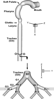
As shown in , the present upper airway model consists of two parts, i.e., an oral airway model, including oral cavity, pharynx, larynx, and trachea, and a symmetric triple bifurcation lung airway model representing generations G0 (trachea) to G3 after CitationWeibel (1963). The dimensions of the oral airway model were adapted from a human cast as reported by CitationCheng et al. (1997). Specifically, the diameter variations along the present oral airway from mouth to trachea are almost the same as those for the hydraulic diameters from the cast. Variations to the actual cast include the circular cross sections, a short mouth inlet with a diameter of 2 cm, a modified soft palate, and a strong bend. The dimensions of the four-generation airway model are similar to those given by CitationWeibel (1963) for adults with a lung volume of 3500 ml. The airway conduit is assumed to be smooth and rigid. The minor effects of cartilaginous rings, which may appear in the upper airways, have not been considered in the present analysis.
Airflow, Heat, and Mass Transfer
To capture the air flow structures in the laminar-to-turbulent flow regimes, i.e., 0 < Relocal < 104 for the human airway configuration during inhalation, the low-Reynolds-number (LRN) k-ω model of CitationWilcox (1998) was selected and adapted which has been demonstrated to be appropriate for such internal flows (CitationZhang and Kleinstreuer 2003b). All transport equations for airflow including continuity, momentum, turbulence kinetic energy, pseudo-vorticity, and energy equations are given in CitationZhang and Kleinstreuer (2003a), Citation(b).
The mass transfer equation for water vapor in the airway stream can be written as
Regional variations in wall temperature were employed as the thermal boundary condition for air at the air-wall interface. The wall temperatures in human airways can be described as (CitationDaviskas et al. 1990):
The mass fraction of water vapor at the wall (Yw) was modeled assuming variable saturation conditions at Tw, i.e.,
The velocity, temperature and vapor concentration fields in the oral and 4-genertion airways are obtained separately. A long exit tube that extends about nine tube diameters from the end of the trachea was used in the oral airway model to eliminate the influence of the zero-pressure assumption at the outlet. However, because the actual length from the glottis to the first carina in the trachea is about 14 cm, the mean-velocity field, turbulence quantities, temperature and mass fraction distributions in the trachea at about 11 cm from the glottis, were adjusted as the inlet conditions of the bifurcating airway segment (i.e., Generations G0 to G3) (see ). The parent tube length of the bifurcation airway model is about 3 cm. Necessary adjustments included: (Equation1) the magnitudes of velocity, turbulence quantities, temperature and water vapor concentration which were recalculated due to the slight variation in trachea diameter (D = 1.37 cm) and Weibel's lung model (D = 1.6 cm); and (2) the profiles of variables were also reconstructed for the inlet to the bronchial airways, G0 to G3, employing an inverse distance weighting method after CitationShepard (1968).
Transport of Micro-Size Droplets
With any given ambient concentration of non-interacting spherical droplets, a Lagrangian frame of reference for the trajectory computations of the evaporating droplets can be employed. In light of the large particle-to-air density ratio, dilute particle suspensions, negligible particle rotation and small thermophoretic forces, drag is the dominant point force. Hence, the particle trajectory equation can be written as
In Equation (Equation6), ui is the instantaneous fluid velocity with ui = [ubar]i +u′i, where [ubar]i is the time-averaged or bulk velocity of the fluid, and u′i are its fluctuating components. Turbulence is assumed to consist of a collection of randomly directed eddies; hence, an eddy-interaction model (EIM) with near-wall correction is used to simulate the particle trajectories, and the fluctuating velocities u′i are obtained by (CitationGosman and Ioannides 1981):
At the mouth inlet, presently uniform droplet distributions were prescribed. The effect of randomized non-uniform droplet inlet distributions on the deposition efficiency has been discussed by CitationZhang and Kleinstreuer (2001). The initial droplet velocities were set equal to that of the fluid, and one-way coupling was assumed between the air and droplet flow fields because the maximum mass loading ratio (mass of particles/mass of fluid) is below 10− 5 in the present analysis. Droplet diameters, positions, velocities and temperatures in the cross section O-O (see ) in the lower trachea were set or adjusted as the inlet particle conditions of the bifurcating airway segment. The adjustment process for particle position and velocity is similar to that for air flow described in the previous subsection.
Droplet Vaporization
In light of the complex liquid-phase aerosols, this analysis assumes that the droplet temperature and composition are maintained spatially uniform but evolve with time and the droplet remains spherical during vaporization (CitationClift et al. 1978). This is reasonable because of the small Biot number (Bi ≪ 1) for micro-size droplets. Considering the convective heat and mass transfer over the whole surface of the spherical droplets, the change in droplet mass can be expressed as (CitationLongest and Kleinstreuer 2004)
In the present study, the relationship between RH d and the solute concentration Cs for the unsaturated and saturated droplet is expressed by the formula derived by CitationCinkotai (1971), i.e.,
The coupled heat transfer equation for liquid droplets reads,
In the present analysis, the saline droplet diameter is always larger than 0.5 μ m with a initial dp ≥ 3 μm and Cs = 0.9%. Hence, Brownian motion of particles with such large diameters in the human upper airways can be neglected (see CitationZhang and Kleinstreuer 2004). The Kelvin and non-continuum effects are minor for droplets with diameters dp ≥ 0.5 μm; however, they are easily incorporated into the simulations for smaller droplets as described in the following section. The Kelvin effect for small droplets can be considered by introducing a factor K (CitationFinlay 2001; CitationAdamson 1990), i.e.,
Whatever is being released by the droplets (see Equations (Equation26) and (Equation27)) becomes a heat and vapor source for the air, possibly affecting the air temperature and vapor concentration (cf. CitationFinlay and Stapleton 1995). However, these source terms are ignored in the present study in light of the low mass loading ratio of droplets (i.e., mass of droplets/ mass of inhaled water vapor < 5 × 10− 4).
Deposition Parameters
The regional deposition of micro-droplets in human airways can be quantified in terms of the deposition fraction (DF) in a specific region (e.g., oral airway, bifurcation airways); it is defined as:
The local deposition patterns of micro-droplets can be quantified in terms of a deposition enhancement factor (DEF). As proposed by Balashazy et al. (1999, 2003), the deposition enhancement factor is defined as the ratio of local to average deposition densities, where deposition densities are computed as the number of deposited droplets in a surface area divided with the size of that surface area. The mathematical expression for DEF is
Clearly, the presence of high DEF-values indicates non-uniform deposition patterns, including “hot spots”, i.e., excessive local concentrations.
NUMERICAL METHOD
The numerical solutions of the governing equations describing fluid velocity, temperature and water vapor concentration fields were carried out with a user-enhanced finite-volume based program, i.e., CFX4.4 from ANSYS, Inc., previously CitationAEA Technology (2001). The numerical program uses a structured, multiblock, body-fitted coordinate discretization scheme (CitationZhang and Kleinstreuer 2002). A Quadratic Upwind (QUICK) differencing scheme, which is third-order accurate in space, was used to model the advective terms of the transport equations. The sets of linearized and discretized equations for all variables were solved using the Block Stone's method.
Once the airflow velocity, temperature and vapor concentration fields were obtained, the droplet transport and evaporation equations were solved with our off-line F90 code with parallelized algorithms (CitationLongest et al. 2004). For the calculation of droplet trajectories, geometry, velocity and turbulence data at all control-volume vertices are first extracted from the CFX solution and written to arrays. A second-order improved Euler predictor-corrector method (CitationLongest et al. 2004) is then used for the integration of the droplet motion equations (see Equation (Equation7)) including turbulent dispersion effects with near-wall correction (see Equations (11–13)) as well as the size-change of droplets (see Equations (24 and 25)). After each iteration for each droplet, the information about position, time, diameter, temperature and three components of the velocity was obtained. Droplet deposition occurs when its center comes within a radius from the wall. The near-wall effects, migration, or resuspension have been currently ignored (CitationLongest and Kleinstreuer 2004). The number of particles at the inlet, n ≥ 10,000, was increased until the deposition fractions became independent of the number of particles simulated.
The computational mesh was generated with CFX Build4. The near-wall region required a very dense mesh. Specifically, the thickness of the near-wall cells was chosen to fully contain the viscous sub-layers and to resolve any geometric features present there. The mesh topology was determined by refining the mesh until grid independence of the flow field solution and droplet deposition fractions was achieved. The computations were performed on an IBM p690 workstation with multiple 1.3 GHZ CPUs. The steady-state solution of the flow field was assumed to be converged when the dimensionless mass residual reached (Total Mass Residual)/(Mass Flow Rate) <10− 3. The convergence of other variables was monitored as well. Typical run times for the fluid flow and mass transfer simulations was approximately 160–500 CPU hours for the oral airway model and 70 CPU hours for the four-generation model under steady inhalation conditions. Utilizing the converged flow field solution, the micro-droplet trajectory and vaporization simulations required approximately 80 to 150 CPU hours for each case simulated.
MODEL VALIDATION
The present computational fluid-particle dynamics (CFPD) model has been validated with various experimental data sets for steady and transient laminar flows in bifurcations (CitationComer et al. 2001; CitationZhang and Kleinstreuer 2002) and for laminar, transitional and turbulent flows in tubes with local obstructions (CitationZhang and Kleinstreuer 2003b). Similarly, micro-particle depositions in airways were successfully compared with measured deposition efficiencies and deposition patterns (CitationComer et al. 2000; CitationZhang et al. 2002a; CitationZhang et al. 2005).
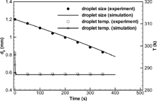
The validation results of droplet vaporization simulations are given in . The simulated temporal diameter and temperature variations of a water droplet is compared with experimental measurements conducted by CitationSmolik et al. (2001), where a water droplet with an initial diameter of 1.2 mm was suspended in a channel with moving air (Tair = 297 K, u∞ = 0.203 m/s, and RH = 35%). It can be seen that the simulated vaporization law for water droplets is in excellent agreement with the experimental data. Considering the droplet temperature, rapid cooling occurs until the droplet wet-bulb condition is reached and then remains basically constant due to the balance between evaporative heat loss and convective heat absorption from the free stream. Concerning the experimental results of CitationSmolik et al. (2001) for a water droplet, the present simulation matches the measured droplet temperature variation very well.
FIG. 2 Comparison of diameter and temperature evolution for a water droplet with the experimental data of CitationSmolik et al. (2001).
The simulated mean air temperatures along the respiratory tract for Tin = 26.7°C and Qin = 30 l/min were compared with the experimental and theoretical results of CitationMcFadden et al. (1985) and CitationDaviskas et al. (1990), respectively, as shown in . It should be noted that airway wall temperatures used in calculations by CitationDaviskas et al. (1990) were directly derived from the experimental data of CitationMcFadden et al. (1985), which naturally results in a closer data match. Thus, a different temperature profile can be expected for the present 3-D simulation of complicated airway geometries when compared to the 2-D calculations with straight tubes as conducted by CitationDaviskas et al. (1990).
FIG. 3 Mean air temperatures in the present simulation compared with experimental values of CitationMcFadden et al. (1985) and calculated results of CitationDaviskas et al. (1990) with Tin = 26.7°C and Qin = 30 l/min.
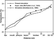
In summary, the good agreements between experimental findings and theoretical predictions instill confidence that the present computer simulation model is sufficiently accurate to analyze laminar-to-turbulent fluid-droplet thermodynamics in three-dimensional oral and upper bronchial airways.
RESULTS AND DISCUSSION
The airflow structures and temperature distributions in the human upper airway model have been discussed by CitationZhang and Kleinstreuer (2003a). This paper focuses on water vapor transport as well as droplet evaporation/hygroscopicity, transport, and deposition while effects of the initial solute concentration on droplet deposition are discussed in CitationZhang et al. (2005b).
Water Vapor Distributions
The 3-D water vapor concentrations are similar to those of fuel vapors, which are described by CitationZhang and Kleinstreuer (2003b). The quantitative variations of water vapor concentrations in the upper airway model (mouth to end-of-trachea) under different inspiratory flow conditions are displayed in in terms of cross-sectional area-averaged relative humidity (RH). Inhalation flow rate as well as air temperature and relative humidity at the mouth inlet are three important factors influencing the variations of water vapor concentrations in human airways. With the transport of water vapor from the airway wall to the unsaturated air stream, the RH increases gradually from the mouth to the trachea and upper bronchial tree. The lower the inlet values (RHin), the higher is the increase rate for the RH due to the larger vapor gradients and wall vapor fluxes (see ). The RH-variation is larger with higher inlet air temperature because the saturation vapor pressure at the liquid/gas interface increases with temperature. The averaged RH in the airway conduits with a lower inlet air temperature (Tin) increases axially much more rapidly than at a higher Tin because of the lower saturated vapor pressure corresponding to the lower temperature (see ). The RH after the trachea can be as high as 84% and 97% at RHin = 20% and 80% for a low inlet temperature of Tin = 283 K. Starting with an initial air temperature of 283 K and an RH of 80%, the maximum RH-value can reach about 104% (i.e., supersaturation) in the pharynx/larynx region. Supersaturation was also reported in the theoretical work by CitationFerron et al. (1985) for nasal breathing at a low inlet air temperature but for a high inlet RH. The occurrence of supersaturation may be attributed to the rapid variations in temperature and vapor concentration.
FIG. 4 Variations of cross-sectional averaged relative humidity with Qin = 30 l/min in: (a) the oral airway model; and (b) the bifurcation airway model G0–G3.
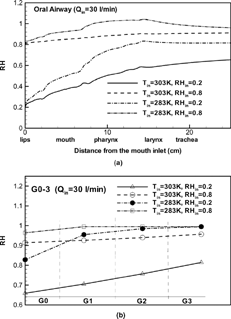
In the airway segments G0 to G3, the mass transfer patterns are strongly affected by the skewed and asymmetric velocity profiles, which indicate different RH distributions in different airway tubes. The mean, cross-sectionally averaged RH values at the outlets of generations G0 to G3 are given in . The RH values at the outlet of G3 vary from 81% to 96%, for 20% ≤ RHin ≤ 80%, Qin = 30 l/min, and Tin = 303 K at the mouth inlet. For the case of Tin = 283 K and RHin ≥ 20%, the RH reach the equilibrium value of 99.5% after generation G1.
Calculation of the Mass Transfer Coefficient
Calculation of the mass transfer coefficient of water vapor in human airways, hm, is helpful in quantitatively predicting the regional water loss or variations of relative humidity of the inhaled air. The mass balance for one airway unit is:
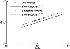
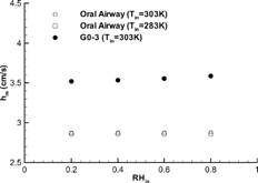
Although the relative humidity and temperature of the incoming air at the mouth inlet (i.e., RHin and Tin) have a significant influence on the variation of the mass fraction in airway conduits, their effects on the vapor mass transfer coefficient (hm) is quite minor (see ). This may be attributed to the fact that both the numerator and denominator in Equation (Equation34) are almost equally dependent on the inlet mass fraction which makes hm only a weak function of RHin and Tin. Hence, the mass transfer coefficient is mainly a function of inspiratory flow rate and diffusion coefficient. Once hm is known, the mass fraction at the exit of an airway unit (Y out ) can be calculated with the following equation which is derived from a mass balance of a micro-element:
FIG. 5 Effects of inlet relative humidity and air temperature on the mass transfer coefficient of water vapor (Qin = 30 l/min).
The mass transfer coefficient can also be nondimensionalized in terms of the Sherwood number (Sh), which is an indicator of convective dispersion, i.e.,
Droplet Evaporation Rate
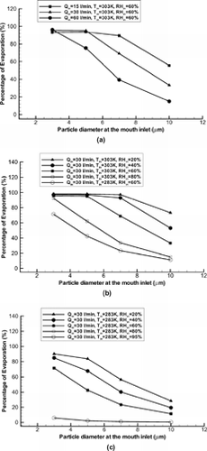
The evaporation rate of droplets (or percentage of droplet evaporation) can be defined as the ratio of total mass loss of all droplets to the total droplet mass at the inlet of the airway section, i.e.,
FIG. 7 Variations of evaporation rate of isotonic saline droplets in the oral airway model under different inhalation conditions: Influence of (a) inhalation flow rate; (b) inlet RH and high Tin; and (c) inlet RH and low Tin.
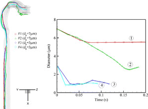
As indicated in Equation (Equation26), the diameter of each droplet, starting at the mouth inlet, decreases gradually due to mass loss by evaporation, and then may increase due to water condensation by hygroscopicity, driven by the airflow field and convective heat/mass transfer. Affected by the highly non-uniform, occasionally turbulent airflow structures in the oral airways, the trajectories for different droplets vary; hence, the changes of droplet diameters are different because of the different local airflow as well as heat and mass transfer. depicts the evolution of both trajectories and diameters in the oral airways, considering four different isotonic saline droplets at Qin = 30 l/min, RHin = 60%, and Tin = 303 K. Even when starting with the same diameters, i.e., 3 and 7 μ m, but different release positions, they undergo contrasting changes depending upon local (moist) environment. Specifically, the diameter of droplet #1 gradually decreases to about 5.5 μ m from the mouth inlet to the glottis due to vaporization; however, it may increase slightly in the trachea when it moves near the airway wall where RH∞ is very high. Droplet #2 may decrease from 7 μ m to 2.6 μ m before it starts to grow after the trachea. Small-size droplets (say, dp = 3 μm, i.e., droplets #3 and #4) may continuously shrink from the inlet until reaching an equilibrium size where they are neither losing nor absorbing water, and then they start to grow or shrink as they move through a high- or low-humidity environment. Clearly, the enhanced solute concentration has a significant effect on vaporization of initially small saline droplets (say, d p ≤ 5 μ m) when compared to cases assuming constant solute concentration (i.e., solute and solvent vaporizes together) or single-component droplets (e.g., pure water droplets). With the assumptions of invariable solute concentration, almost all initially small-size droplets evaporate in the oral airways when RHin ≤ 60%, Qin ≤ 30 l/min and Tin = 303 K and hence very few droplets can enter the tracheobrochial airways. However, the absolute change of deposition fraction may tend to be minor in the human upper airways because inertial deposition is small for small-size microparticles. The hygroscopic growth of such droplets is larger in the lower airways and alveolar regions. The effect of enhanced solute concentration is relatively minor for large microdroplets.
FIG. 8 Trajectories and diameter evolution of selected isotonic saline droplets in the oral airway model with Qin = 30 l/min, Tin = 303 K and RHin = 60%.
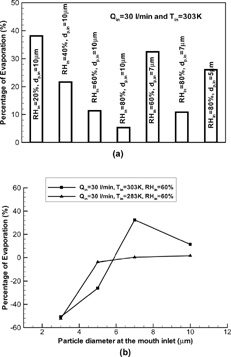
shows the percentages of isotonic saline droplet evaporation in the bifurcating airway model G0 to G3. The negative values of evaporation rate in indicate water condensation on the droplet surface. With water evaporation or condensation and air humidification in the oral passages, droplet vaporization or hygroscopicity becomes more complicated in the upper tracheobronchial airways. Large isotonic saline droplets (say, dp > 5 μm) may continuously vaporize with incoming air at high Tin (say, Tin = 303 K) and RHin ≤ 80%. The effects of RHin and dp,in on evaporation are similar to those in the oral airways for such droplets (see ). However, hygroscopicity is of importance for small-size droplets (dp < 5 μm) even with a high Tin (say, Tin = 303 K and RHin ≤ 80%; see ) because the enhanced solution concentration due to evaporation in the oral passages greatly reduces the vapor concentration on the droplet surface (see Equation (Equation19)). Droplet vaporization becomes minor (< 2%) for all size droplets with dp,in ≤ 10 μm in the tracheobronchial airways G0–G3, when the incoming air temperature is low (say, Tin = 283 K) and RHin ≥ 60% due to the air humidification in the oral passages (see ).
FIG. 9 Evaporation rate of isotonic saline droplets in the bifurcation airway model G0-G3 under different inhalation conditions: Influence of (a) inlet RH, initial particle size and high Tin; and (b) initial particle size and inlet air temperature.
As shown in , the monodisperse droplets entering at the mouth inlet turn polydisperse during vaporization. shows the cumulative distribution function of the droplet size at the outlet of the oral airways, or the inlet to the first bifurcation, for different inhalation rates and inlet air temperatures. The fraction less than a particular size can be obtained directly from the graph. The fraction of particles having diameters between two sizes can be determined from the difference of the cumulative fractions for these two sizes. The initial droplet size was a uniform distribution with dp = 10 μm. As expected, the change of droplet size decreases with increasing flow rate due to decreasing residence times. The variation in such large droplet size is larger with lower inlet relative humidity because the water vapor pressure in the free air stream decreases with RHin. The mean droplet diameters for initially 10 μm-droplets after the oral airways are dp = 7.57, 8.51, 9.16 μm for Qin = 15, 30, 60 l/min with Tin = 303 K and RHin = 60%, respectively, and dp = 5.99, 7.43, 9.36 μm for RHin = 20%, 40% and 80% with Qin = 30 l/min and Tin = 303 K. The variations in droplet size should greatly influence droplet deposition downstream. Clearly, the variation of droplet size is smaller with lower inlet air temperatures because the local RH in the conduits increases with decreasing temperature. The mean droplet diameters after the oral airways are dp = 8.84, 9.24, 9.58, 9.84, and 9.98 μm for RHin = 20%, 40%, 60%, 80%, and 95% with Qin = 30 l/min, Tin = 283 K and initial droplet diameter of 10 μm, respectively.
FIG. 10 Cumulative distribution of isotonic saline droplet sizes at the inlet of the bifurcation airway model: Influence of (a) inhalation flow rate; (b) inlet RH and high Tin; and (c) inlet RH and low Tin.
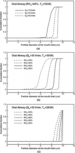
The illustrations for evaporation and size change (see , , , ) also demonstrate that vaporization is dominant for isotonic droplets with a relatively large initial size (dp,in > 6 μ m) in the human upper airway when compared to hygroscopicity for incoming air of RHin ≤ 95% and Tin ≥ 283 K. For the small-size isotonic droplets (e.g., dp,in < 6 μm), hygroscopicity may become significant after the trachea even if the inlet RH is relatively low (say, RHin = 60%) and Tin is high (say, Tin = 303 K).
Droplet Deposition Pattern
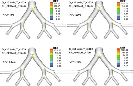
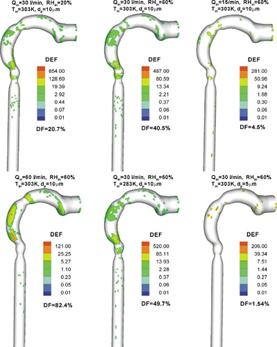
The 3-D surface views of the local droplet deposition patterns in terms of deposition enhancement factor DEF (see Equation (Equation31)) for isotonic saline droplets with different combinations of dp,in, Qin, Tin, and RHin are shown in . Clearly, micro-droplet deposition during inhalation is mainly due to impaction, secondary flow convection, and turbulent dispersion. Thus, they mainly deposit at stagnation points for axial particle motion, such as the tongue portion in the oral cavity, the outer bend of the pharynx/larynx, and the regions just upstream of the glottis and the straight tracheal tube. As shown in , the maximum DEF-values are in the range of 100 to 900, which vary with the flow rate, initial particle size and inlet air parameter. This implies that the deposition patterns of micro-droplets in the oral airway are highly non-uniform, and hence a small surface area, where the maximum DEF occurs, may receive hundred times higher dosages when compared to the average value for the entire airways. Such a site of massive particle deposition is usually located in the glottis region and/or the outer bend in, or just after, the curved pharynx region for relatively large-size droplets (say, dp = 10 μ m). Relatively small-size droplets (say, dp = 5 μ m) may vaporize very rapidly and only deposit at the initial part of the oral airways (see ).
FIG. 11 3-D distributions of deposition enhancement factor (DEF) in the oral airway model for micro-size isotonic saline droplets.
depicts the distributions of DEFs in the bifurcation airway model G0 to G3, i.e., part of the bronchial tree. As expected, for micro-particles the high DEF values appear mainly around the carinal ridges due to inertial impaction, but the specific distribution of DEFs at each carina is different and varies with the inhalation parameters as well. Some micro-droplets also land outside the vicinities of the carinal ridges due to secondary flows and turbulent dispersion. However, the deposition sites of vaporizing droplets are not as broad as for non-vaporizing particles (see CitationZhang et al. 2005a). In the bifurcation airway model, the maximum DEF-values range from 400 to 1500 for the cases shown in . The variations of maximum DEF-values for the given initial droplet diameter and inlet airflow conditions are complex, generating similar patterns as those for non-vaporizing particles (see CitationZhang et al. 2005a). The regional droplet deposition fractions (DF) (see Equation (Equation30)) are also given in and . Clearly, the change of particle size due to evaporation greatly affects isotonic saline droplet deposition. The variation in DF is a function of initial droplet diameter, inlet temperature, RH, and flow rate, when considering droplet vaporization.
CONCLUSIONS
The methodology for simulating water vapor and heat transfer as well as transport and deposition of vaporizing droplets has been discussed. As an example, the evaporation/ hygroscopicity, transport and deposition of isotonic saline droplets (NaCl ≈ 0.9%) have been simulated for the human upper airways and analyzed for different steady inhalation conditions. The results indicate the following:
| 1. | With the transport of water vapor from the airway wall to the unsaturated air stream, the relative humidity (RH) of the air flow increases gradually from the mouth to the trachea and upper bronchial tree as a function of inhalation flow rate, temperature and RH-value of air at the mouth inlet. The RH-values after generation G3 are in the range of 81% to 100%, when the inlet conditions are 20% ≤ RHin ≤ 80%, Qin ≤ 30 l/min, and Tin ≤ 303 K. | ||||
| 2. | The inlet relative humidity and air temperature have almost no effect on the mass transfer coefficients of water vapor in airway conduits. Thus, the mass transfer coefficients of vapors in the upper airway in terms of Sh-number can be correlated as a function of the product of Reynolds (Re) and Schmidt (Sc) numbers, i.e., | ||||
| 3. | Saline droplets, initially with dp ≤ 5 μm, may evaporate more than 95% of their mass in the oral airways when RHin ≤ 60%, Qin ≤ 30 l/min and Tin = 303 K. Increasing the relative humidity or decreasing the temperature of the incoming air, or increasing the inspiratory flow rate, is helpful in reducing vaporization of saline droplets. | ||||
| 4. | Vaporization is dominant for isotonic saline droplets with a relatively large initial size (dp,in > 6 μm) in the human upper airways when compared to hygroscopicity for incoming air of RHin ≤ 95% and Tin ≥ 283 K. For small droplets (e.g., dp,in < 6 μm), hygroscopicity may become significant after the trachea even if the inlet RH is relatively low (say, RHin = 60%) and Tin is high (say, Tin = 303 K). | ||||
| 5. | Deposition sites of vaporizing droplets are more confined when compared with constant-diameter particles; however, the deposition enhancement factors are in the same order of magnitude (i.e., 102–103) for these two types of aerosols. | ||||
Acknowledgments
The views and conclusions contained herein are those of the authors and should not be interpreted as necessarily representing the official policies or endorsements, either expressed or implied, of the Air Force Office of Scientific Research or the U.S. Environmental Protection Agency.
This effort was sponsored by the Air Force Office of Scientific Research, Air Force Material Command, USAF, under grant number FA9550-04-1-0422 (Dr. Walt Kozumbo, Program Manager) and the US Environmental Protection Agency (Dr. C. S. Kim, Program Monitor). The U.S. Government is authorized to reproduce and distribute reprints for governmental purposes notwithstanding any copyright notation thereon. The use of both CFX software from ANSYS Inc. (Canonsburg, PA) and the IBM p690 at the High Performance Computing Center at North Carolina State University (Raleigh, NC) are gratefully acknowledged as well.
REFERENCES
- Adamson , A. W. 1990 . Physical Chemistry of Surfaces , 5th edn. , New York : Wiley .
- AEA Technology . 2001 . CFX-4.4: Solve , Oxfordshire, , UK : CFX International .
- Balásházy , I. , Hofmann , W. and Heistracher , T. 1999 . Computation of Local Enhancement Factors for the Quantification of Particle Deposition Patterns in Airway Bifurcations . J. Aerosol Sci. , 30 : 185 – 203 . [CSA]
- Balásházy , I. , Hofmann , W. and Heistracher , T. 2003 . Local Particle Deposition Patterns may Play a Key Role in the Development of Lung Cancer . J. Appl. Physiol. , 94 : 1719 – 1725 . [CSA]
- Benaissa , A. , Gauthier , J. E. D. , Bardon , M. F. and Laviolette , M. 2002 . Modelling Evaporation of Multicomponent Fuel Droplets under Ambient Temperature Conditions . J. Inst. Energy , 75 : 19 – 26 . [CSA]
- Berlemont , A. , Grancher , M. S. and Gouesbet , G. 1995 . Heat and Mass Transfer Coupling between Vaporizing Droplets and Turbulence using a Lagrangian Approach . Int. J. Heat Mass Transfer , 38 : 3023 – 3034 . [CROSSREF] [CSA]
- Broday , D. M. and Georgopoulos , P. G. 2001 . Growth and Deposition of Hygroscopic Particulate Matter in the Human Lungs . Aerosol Sci. Technol. , 34 : 144 – 159 . [CSA]
- Chen , W. Y. and Horton , D. J. 1977 . Heat and Water Loss from the Airways and Exercise-Induced Asthma . Respiration , 34 : 305 – 313 . [CSA]
- Cheng , K. H. , Cheng , Y. S. , Yeh , H. C. and Swift , D. L. 1997 . Measurements of Airway Dimensions and Calculation of Mass Transfer Characteristics of the Human Oral Passage . J. Biomechanical Engineering–Trans of the ASME , 119 : 476 – 482 . [CSA]
- Cinkotai , F. F. 1971 . The Behavior of Sodium Chloride Particles in Moist Air . J. Aerosol Sci. , 2 : 325 – 329 . [CROSSREF] [CSA]
- Clift , R. , Grace , J. R. and Weber , M. E. 1978 . Bubbles, Drops, and Particles , New York : Academic Press .
- Comer , J. K. , Kleinstreuer , C. , Hyun , S. and Kim , C. S. 2000 . Aerosol Transport and Deposition in Sequentially Bifurcating Airways . J Biomechanical Engineering – Trans of the ASME , 122 : 152 – 158 . [CSA]
- Comer , J. K. , Kleinstreuer , C. and Zhang , Z. 2001 . Flow Structures and Particle Deposition Patterns in Double Bifurcation Airway Models. Part 1. Air Flow Fields . J Fluid Mechanics , 435 : 25 – 54 . [CROSSREF] [CSA]
- Daviskas , E. , Gonda , I. and Anderson , S. D. 1990 . Mathematical Modeling of Heat and Water Transport in Human Respiratory Tract . J. Appl. Physiol. , 69 ( 1 ) : 362 – 372 . [PUBMED] [INFOTRIEVE] [CSA]
- Eisner , A. D. , Graham , R. C. and Martonen , T. B. 1990 . Coupled Mass and Energy Transport Phenomena in Aerosol/Vapor-Laden Gases – I. Theory of the Hygroscopic Aerosol Effects on Temperature and Relative Humidity Patterns of Inspired Air . J. Aerosol Sci. , 21 : 833 – 848 . [CROSSREF] [CSA]
- Ferron , G. A. , Haider , B. and Kreyling , W. G. 1985 . A Method for the Approximation of the Relative Humidity in The Upper Airways . Bull. Math. Biol. , 47 : 565 – 589 . [PUBMED] [INFOTRIEVE] [CROSSREF] [CSA]
- Ferron , G. A. , Kreyling , W. G. and Haider , B. 1988 . Inhalation of Salt Aerosol Particles II. Growth and Deposition in the Human Respiratory Tract . J. Aerosol Sci. , 19 ( 4 ) : 611 – 631 . [CROSSREF] [CSA]
- Ferron , G. A. , Oberdörster , G. and Henneberg , R. 1989 . Estimation of the Deposition of Aerosolized Drugs in the Human Respiratory Tract due to Hygroscopic Growth . J. Aerosol Med. , 2 : 271 – 284 . [CSA]
- Finlay , W. H. 2001 . The Mechanics of Inhaled Pharmaceutical Aerosols: An Introduction. , London : Academic Press .
- Finlay , W. H. and Stapleton , K. W. 1995 . The Effect on Regional Lung Deposition of Coupled Heat and Mass Transfer between Hygroscopic Droplets and their Surrounding Phase . J. Aerosol Sci. , 26 ( 3 ) : 655 – 670 . [CROSSREF] [CSA]
- Finlay , W. H. , Stapleton , K. W. , Chan , H. K. , Zuberbuhler , P. and Gonda , I. 1996 . Regional Deposition of Inhaled Hygroscopic Aerosols: In Vivo SPECT Compared with Mathematical Modeling . J. Appl. Physiol. , 81 : 374 – 383 . [CSA]
- Gebheart , J. , Anselm , A. , Ferron , G. , Heyder , J. and Stahlhofen , W. 1990 . “ Experimental Data on the Total Deposition of Hygroscopic Particles in the Human Respiratory Tract ” . In Aerosols: Science, Industry, Health and Environment , Edited by: Masuda , S. and Takahashi , K. pp.1299 – 1302 . Oxford : Pergamon Press .
- Gosman , A. D. and Ioannides , E. 1981 . Aspects of Computer Simulation of Liquid-Fueled Combustors . J. Energy , 7 : 482 – 490 . [CSA]
- Hanna , L. M. and Scherer , P. 1986 . A Theoretical Model of Localized Heat and Water Transport in the Human Respiratory Tract . J. Biomech. Eng. , 108 : 19 – 27 . [CSA]
- Hickey , A. J. and Martonen , T. B. 1991 . Behavior of Hygroscopic Pharmaceutical Aerosols and the influence of Hydrophobic Additives . Pharm. Res. , 10 : 1 – 7 . [CROSSREF] [CSA]
- Hinds , W. C. 1993 . “ Physical and chemical changes in the particulate phase ” . In Aerosol Measurements, Pronciples, techniques and Applications. , Edited by: Willeke , K. and Baron , P. A. New York : Van Nostrand Reinhold .
- Ingenito , E. P. , Solway , J. , McFadden , E. R. Jr. , Pichurko , B. M. , Cravalho , E. G. and Drazen , J. M. 1986 . Finite Difference Analysis of Respiratory Heat Transfer . J. Appl. Physiol. , 61 : 2252 – 2259 . [PUBMED] [INFOTRIEVE] [CSA]
- Johnson , C. E. , Linderoth , L. S. Jr. and Nuckols , M. L. 1977 . An Analysis of Sensible Respiratory Heat Exchange during Inspiration under Environmental Condition of Deep Diving . J Biomechanical Engineering -Trans of the ASME , 99 : 45 – 53 . [CSA]
- Kim , J. , Moin , P. and Moser , R. D. 1987 . Turbulence Statistics in Fully Developed Channel Flow at Low Reynolds Number . J. Fluid Mechanics , 177 : 133 – 166 . [CSA]
- Kleinstreuer , C. and Zhang , Z. 2003 . Laminar-to-Turbulent Fluid-Particle Flows in a Human Airway Model . Int. J. Multiphase Flow , 29 : 271 – 289 . [CROSSREF] [CSA]
- Longest , P. W. and Kleinstreuer , C. 2004 . Interacting Effects of Uniform Flow, Plane Shear, and Near-Wall Proximity on the Heat and Mass Transfer of Respiratory Aerosols . Int. J. Heat and Mass Transfer , 47 : 4745 – 4759 . [CROSSREF] [CSA]
- Longest , P. W. , Kleinstreuer , C. and Buchanan , J. R. 2004 . Efficient Computation of Micro-Particle Dynamics Including Wall Effect . Computers & Fluids. , 33 : 577 – 601 . [CROSSREF] [CSA]
- MacInnes , J. M. and Bracco , F. V. 1992 . Stochastic Particle Dispersion Modeling and The Tracer-Particle Limit . Physics of Fluids , 4 : 2809 – 2824 . [CROSSREF] [CSA]
- Matida , E. A. , Nishino , K. and Torii , K. 2000 . Statistical Simulation of Particle Deposition on the Wall from Turbulent Dispersed Pipe Flow . Int. J. Heat and Fluid Flow , 21 : 389 – 402 . [CROSSREF] [CSA]
- Matida , E. A. , Finlay , W. H. , Lange , C. F. and Grgic , B. 2004 . Improving Numerical Simulations of Particle Deposition in an Idealized Mouth-Throat . J. Aerosol Sci. , 35 : 1 – 19 . [CROSSREF] [CSA]
- McFadden , E. R. , Pichurko , B. M. , Bowman , H. F. , Ingenito , E. , Burns , S. , Dowling , N. and Solway , J. 1985 . Thermal Mapping of the Airways in Humans . J. Applied Physiol. , 58 : 564 – 570 . [CROSSREF] [CSA]
- Morrow , P. E. 1986 . Factors Determining Hygroscopic Aerosol Deposition in Airways . Physiol. Rev. , 66 : 330 – 376 . [PUBMED] [INFOTRIEVE] [CSA]
- Naftali , S. , Schroter , R. C. , Shiner , R. J. and Elad , D. 1998 . Transport Phenomena in the Human Nasal Cavity: A Computational Model . Annals of Biomedical Engineer , 26 : 831 – 839 . [CROSSREF] [CSA]
- Nuckols , M. L. 1981 . Heat and Water Transfer in the Human Respiratory System at Hyperbaric Conditions , Durham, NC : Duke University . PhD thesis
- Peng , C. , Chow , A. H. L. and Chan , C. K. 2000 . Study of the Hygroscopic Properties of Selected Pharmaceutical Aerosols Using Single Particle Levitation . Pharmaceutical Research , 17 : 1104 – 1109 . [PUBMED] [INFOTRIEVE] [CROSSREF] [CSA]
- Schuen , J. S. , Chen , L. D. and Faeth , G. M. 1983 . Evaluation of a Stochastic Model of Particle Dispersion in a Turbulent Round Jet . AICHE J. , 29 : 167 – 170 . [CROSSREF] [CSA]
- Shepard , D. 1968 . A Two-dimensional Interpolation Function for Irregularly-Spaced Data . Proc. 23rd National Conference ACM . 1968 . pp. 517 – 524 . ACM .
- Smolik , J. , Dzumbova , L. , Schwarz , J. and Kulmala , M. 2001 . Evaporation of Ventilated Water Droplet: Connection between Heat and Mass Transfer . J. Aerosol Sci. , 32 : 739 – 748 . [CROSSREF] [CSA]
- Tawhai , M. H. and Hunter , P. J. 2004 . Modeling Water Vapor and Heat Transfer in the Normal and the Intubated Airways . Annals of Biomedical Engineer. , 32 : 609 – 622 . [CROSSREF] [CSA]
- Vargaftik , N. B. 1975 . Tables on Thermophysical Properties of Liquids and Gases , 2nd Ed. , Washington, DC : Hemisphere .
- Vesala , T. , Kulmala , M. , Rudolf , R. , Vrtala , A. and Wagner , P. 1997 . Models for Condensational Growth and Evaporation of Binary Aerosol Particles . J. Aerosol Sci. , 28 : 565 [CROSSREF] [CSA]
- Wang , Y. and James , P. W. 1999 . On the Effect of Anisotropy on the Turbulent Dispersion and Deposition of Small Particles . Int. J. Multiphase Flow , 25 : 551 – 558 . [CROSSREF] [CSA]
- Weibel , E. R. 1963 . Morphometry of the Human Lung , New York : Academic Press .
- Wilcox , D. C. 1998 . Turbulence Modeling for CFD , Second Edition , LA, , Canada CA : DCW Industries, Inc. .
- Williams , R. , Rankin , N. , Smith , T. , Galler , D. and Seakins , P. 1996 . Relationship between the Humidity and Temperature of Inspired Gas and the Function of the Airway Mucosa . Crit. Care Med. , 24 : 1920 – 1929 . [PUBMED] [INFOTRIEVE] [CROSSREF] [CSA]
- Zhang , Z. and Kleinstreuer , C. 2001 . Effect of Particle Inlet Distributions on Deposition in a Triple Bifurcation Lung Airway Model . J. Aerosol Medicine , 14 : 13 – 29 . [CROSSREF] [CSA]
- Zhang , Z. and Kleinstreuer , C. 2002 . Transient Airflow Structures and Particle Transport in a Sequentially Branching Lung Airway Model . Physics of Fluids , 14 : 862 – 880 . [CROSSREF] [CSA]
- Zhang , Z. and Kleinstreuer , C. 2003a . Low Reynolds Number Turbulent Flows in Locally Constricted Conduits: A Comparison Study . AIAA Journal , 41 : 831 – 840 . [CSA]
- Zhang , Z. and Kleinstreuer , C . 2003b . Species Heat and Mass Transfer in a Human Upper Airway Model . Int. J. Heat and Mass Transfer , 46 : 4755 – 4768 . [CROSSREF] [CSA]
- Zhang , Z. and Kleinstreuer , C . 2004 . Airflow Structures and Nano-Particle Deposition in a Human Upper Airway Model . J. Computational Phys. , 198 : 178 – 210 . [CROSSREF] [CSA]
- Zhang , Z. , Kleinstreuer , C. , Donohue , J. F. and Kim , C. S. 2005a . Comparison of Micro- and Nano-Size Particle Depositions in a Human Upper Airway Model . J. Aerosol Sci. , 36 : 211 – 233 . [CROSSREF] [CSA]
- Zhang , Z. , Kleinstreuer , C. and Kim , C. S. 2002a . Cyclic Micron-Size Particle Inhalation and Deposition in a Triple Bifurcation Lung Airway Model . J. Aerosol Sci. , 33 : 257 – 281 . [CROSSREF] [CSA]
- Zhang , Z. , Kleinstreuer , C. and Kim , C. S. 2002b . Aerosol Deposition Efficiencies and Upstream Release Positions for Different Inhalation Modes in an Upper Bronchial Airway Model . Aerosol Sci. Technol. , 36 : 828 – 844 . [CROSSREF] [CSA]
- Zhang , Z. , Kleinstreuer , C. and Kim , C. S. 2005b . Isotonic and Hypertonic Saline Droplet Deposition in a Human Upper Airway Model . J. Aerosol Med. , submitted for publication[CSA]
