Abstract
Most of the nanoparticle number emissions from diesel engines are found in the nucleation mode (D p < ∼ 30nm). These nanoparticles are mainly formed by nucleation as diesel engine exhaust gas cools and dilutes in the atmosphere. Diesel nanoparticles have raised concerns because of their suspected human health effects. There are two main theories describing diesel nanoparticle nucleation: homogeneous nucleation, most likely binary of sulfuric acid and water, and ion-induced nucleation. In this study we assess the likelihood of the ionic mechanism. Previous studies have shown that diesel nucleation mode particles carry little or no electrical charge (CitationJung and Kittelson 2005). This could be due to the fact that those particles were never charged, or it could be due to the fact that they were neutralized quickly during dilution and sampling. In the first part of this study, we estimated the extent of neutralization of charged nuclei during the dilution process and found it too slow compared to the residence time in our system to account for the absence of charge observed in previous work. In the second part of this study, we compared nuclei mode formation with and without chemi-ions during dilution and sampling by using an ion trap at the upstream of dilution. Removing upstream ions had no significant influence on the nucleation mode, suggesting that ionic nucleation did not play an important role. We also calculated ion concentration histories, accounting for recombination and attachment during expansion stroke in after combustion. This calculation indicates that ion concentration in the exhaust is too low to account for nucleation mode formation.
INTRODUCTION
Despite the numerous technological improvements that have been made regarding diesel particle traps in an effort to lower the carbonaceous particle emissions, legislators and researchers are still concerned about nanoparticle emissions. Most diesel nanoparticles form during the dilution process by gas-to-particle conversion processes, so it is possible for diesel nanoparticles to form downstream of particulate filters, which are able to remove solid particles but not necessarily gas phase particle precursors (CitationKittelson et al. 2006a, Citation2006b). In an effort to control nanoparticle emissions, the European Union is considering regulating particle number concentration in addition to particle mass, but so far the plan is to only regulate solid particle emissions. Volatile nanoparticles are currently unregulated, but a further understanding of how they form will be beneficial in assessing their potential health effects and formulating control strategies.
Particles found in diluted diesel exhaust are found in three size modes, the nucleation mode, D p < ∼ 30 nm, the accumulation mode, ∼ 30 nm < D p < ∼ 500 nm, and the coarse mode, ∼ 500 nm < D p < ∼ 10 μ m (CitationKittelson 1998). The precise boundaries between the three size modes vary, but the nature of the particles in the three modes is quite different. The nucleation mode is where freshly nucleated particles are found. The accumulation mode is where most of the soot is found. The coarse mode contains mainly soot particles that have been deposited on surfaces and subsequently re-entrained. This study focuses on the nucleation mode.
Early work on the measurement of charge on diesel particles showed that solid soot particles found in the accumulation mode carried a significant bipolar charge, but volatile particles found mainly in the nucleation mode had little or no charge (CitationCollings et al. 1988; CitationMoon 1984). Charging was postulated to take place by attachment of chemi-ions formed early in the combustion process under high temperature conditions. It was suggested that the charging froze part way through the expansion stroke when most of the ions had been lost by either recombination or attachment. These results were largely confirmed in more recent work by CitationJung and Kittelson (2005). They measured particle charged fractions as a function of size using an electrostatic filter placed at the downstream of a dilution tunnel. Again, very little charge was found on nucleation mode particles. The lack of charge on nucleation mode particles led them to conclude that ion-induced nucleation is not the primary mechanism for the nucleation of diesel nanoparticles. However, ionic nucleation could not be completely ruled out because experimental uncertainty made it impossible to ascertain that there was no charge on the nucleation mode particles. Further, Yu et al. (Citation2001, Citation2002, Citation2004) have argued strongly that ionic nucleation is an important mechanism in the formation of the nucleation mode in diluted diesel exhaust. CitationYu (2001) claimed that the ion induced nucleation theory agrees well with measurements in terms of total nanoparticle concentrations, their sensitivity to fuel sulfur content and second stage dilution conditions, assuming an ion concentration of 1.5· 108 cm− 3 in diesel exhaust. CitationYu et al. (2004) supported Yu's previous study by measuring ion concentration in the exhaust. Most of their ions were in the range from 3 to 10 nm, and total ion (up to 10 nm) concentration was measured as 2.7· 108 cm–3.
One of the goals of this study was to estimate the charge level that would be expected on the nucleation mode if it were formed by bipolar ionic nucleation. This was done by calculating the extent of neutralization of charged nuclei during dilution and sampling. The results of this study suggest that the neutralization of charged nuclei is too slow to reduce the charge to the low levels observed experimentally in the previous study.
In this study, we placed an ion trap, which is similar to the electrostatic filter used in the previous study but smaller in size and applied voltage, at the upstream of the dilution tunnel to remove the influence of ionic particle precursors. This was done to crosscheck the results found from the previous study. We also calculated the temporal change of ion concentration, accounting for recombination and attachment during the expansion stroke in diesel combustion. This was done in order to examine whether ion-induced nucleation is feasible to any extent.
EXPERIMENTAL SETUP
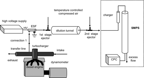
shows the schematic diagrams of the experimental setup, including an engine bench, sampling system, dilution tunnel, and a particle sizer, specifically a Scanning Mobility Particle Sizer (SMPS). In this study, the diesel combustion exhaust was sampled at 25 cm downstream of the turbocharger exit and was diluted in a two-stage-air-ejector dilution tunnel (CitationAbdul-Khalek et al. 1999). An Electrostatic Filter (ESF) was placed at the upstream of the two-stage dilution system as an ion trap. The dilution system contained a two-stage dilution tunnel, in which two ejectors (TD 260 and TD110, Air-Vac Engineering Inc, Seymour, CT) were used to dilute the engine exhaust. Both ejectors were driven by particle-free, dry, compressed air (30 psi). The compressed air for the first stage ejector passed through an ice bath and then went through a heating section, where the temperature was controlled to set the tunnel temperature at 30°C. The total dilution ratio was 360 for 10% load under 1400 rpm.
Engine
The engine used in this study is a medium-duty, direct injection, 4 cylinder, 4 cycle, mid-90s turbocharged diesel engine (John Deere T04045TF250) of 4.5 L displacement, with a peak power output of 125 HP (93 kW) at 2400 rpm and a peak torque output of 400 N· m at 1400 rpm. The output of the engine was coupled with a dynamometer for load control. The engine was operated at 1400 rpm under 10 % load (40 N· m).
Electrostatic Filter (ESF)
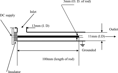
The ESF is composed of an aluminum cylinder with a concentric rod at the center, as shown in . This is the same type of the ESF used in the previous study (CitationJung and Kittelson 2005) except smaller size to minimize surface interactions. Particle laden flow was introduced in the radial direction, while the flow exits in the longitudinal direction. The mobility (Z p ) of a singly charged 10 nm diameter particle is 6.22 cm2stV− 1s–1 at STP conditions where 1st V = 300 V. The minimum bias voltage to the center rod with outer cylinder grounded to collect the particles and electrical species such as ions smaller than 10 nm becomes 0.207st V (= 62.2 V) neglecting entrance effect of the flow and assuming laminar flow condition. We applied 200 Volts DC to ensure that all small ions were removed. Although the charged fraction of accumulation mode particles is high, we expect a loss of less than 1% of accumulation particles at 200 Volts DC assuming the charge level measured by CitationMoon (1984) and CitationKittelson et al. (1986). ESF was thermally insulated with glass fiber tapes to minimize the exhaust gas cooling.
Evolution of Particle Charge
It is widely accepted that the nucleation of nanoparticles from diesel exhaust takes place as the exhaust, which contains gas-phase particle precursors, cools down during the dilution process (CitationAbdul-Khalek et al. 1999; CitationCollings and Graskow 2000; CitationShi and Harrison 1999; CitationVouitsis et al. 2005). Assuming the nucleation takes place in the beginning of primary dilution, we ran a calculation to determine the change in the charged fraction of nuclei mode particles. The goal of this calculation was to assess the extent of the neutralization of nuclei mode particles at the end point of measurement. This was done to confirm that the method (used in our previous study to examine ion-induced nucleation mechanism) essentially measures the original charged fraction without significant influence by particle neutralization. Several assumptions, which include initial conditions, were made in order to perform the calculation, as set forth below:
| • | All ions were used for ionic nucleation. | ||||
| • | Nucleation takes place during the primary dilution process and secondary dilution quenches nucleation (CitationAbdul-Khalek et al. 1999; CitationKhalek et al. 2000; CitationShi and Harrison 1999). | ||||
| • | Nuclei mode particle size grows mostly by condensation in the dilution tunnel. | ||||
| • | Nuclei mode particles are monodisperse. | ||||
| • | Coagulation between oppositely charged nuclei mode particles is the fastest type of coagulation, and the other types of coagulation have a negligible influence on the evolution of the charged fraction. | ||||
| • | Coagulation after secondary dilution is negligible. In other words, the charged fraction is frozen after secondary dilution. | ||||
CitationKhalek et al. (2000) measured the growth of diesel nanoparticles in a dilution residence chamber and showed that growth rates were consistent with mainly hydrocarbon and some sulfate condensation on primary nuclei. CitationVouitsis et al. (2005) demonstrated computationally that the measured volume concentration of nucleation mode particles can only be reached if hydrocarbon condensation occurs on the sulfuric acid-water nuclei. Particle growth is significant at the first stage of the dilution because the concentrations of growth precursors are high. The growth rate is engine dependent since it is proportional to hydrocarbon and sulfate precursor concentrations. However, as an initial guess we used the value of 11 nm/s measured by CitationKhalek et al. (2000) using a similar dilution system and engine of different manufacture but similar size and application to the one used in this study. They expressed particle diameter as:
The particle coagulation coefficient (K 11) with the same diameter in free molecular regime is:
In this calculation, only coagulation of nuclei mode particles was considered because they outnumbered accumulation mode particles by orders of magnitude. Also only coagulation of oppositely charged particles was considered, because once uncharged particles form they coagulate much slower. The nuclei mode particle concentration (N) at first stage of dilution can be expressed as the sum of the charged (N c ) and the uncharged (N uc ) particles:
Experimental Measurements of the Influence of Ion Removal on Nucleation
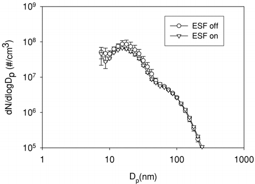
Size distributions were measured with and without turning on the ESF before the residence chamber. There is no distinguishable difference in size distribution between ESF on and off as shown in . This provides further evidence that ion-induced nucleation is not a dominant mechanism. If ions played an important role for particle nucleation, one would expect a decrease in size distribution with ESF on, which is designed to remove all ions less than 10 nm. The exhaust temperature was 160°C at the 1400 rpm 10% load condition and the transfer line and ESF were thermally insulated with glass fiber tape to prevent the exhaust gas from cooling prior to dilution, minimizing nucleation in the transfer line and ESF.
Evolution of Ion Concentration During Expansion Stroke
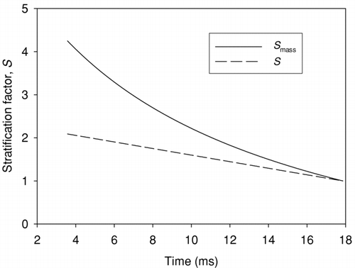
The history of ion concentration was calculated during expansion stroke of the diesel engine to estimate ion concentration in the exhaust. The calculation was performed for the engine used in this study under the same engine operating condition as the experimental condition using Engineering Equation Solver (version 7, F-Chart Software, Madison, WI) to solve the following governing equations.
The displacement volume (V d ) is 1125 cm3, while the compression ratio (r) is 18. The evolution of ion concentration was calculated from t min (CA30, 3.57 ms), when the ion concentration is thought to be maximum, to t max (CA150, 17.9 ms) when the exhaust valve opens to emit combustion products. Volume change during expansion stroke can be calculated using Equations (12–14):
Pressure and temperature changes were determined assuming polytropic relation, P · V n = constant (CitationHeywood 1988), as shown in Equations (23–27):
Ion concentration change is governed by the following Equations (32–36):
FIG. 5 Mixture and chamber average temperatures and ion recombination coefficient plotted against time during expansion stroke.
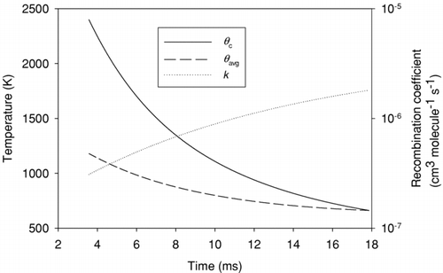
FIG. 6 Rates of ion removal by recombination (−dn1/dt) and attachment to the surface of soot particles (−dn3/dt).
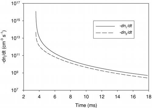
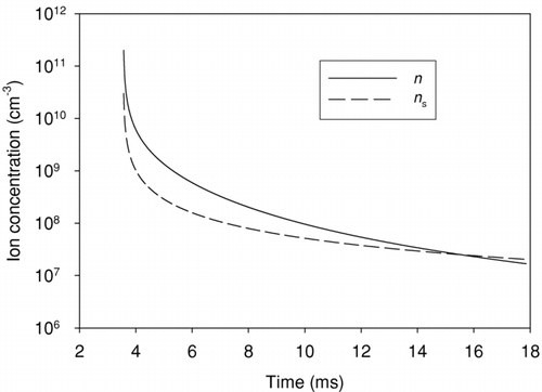
FIG. 7 Evolution of ion concentration during expansion stroke, concentration in the cylinder and concentration corrected to standard conditions are shown.
Although expansion and mixing reduce local ion concentrations during the expansion, only recombination and surface attachment reduce the total number of ions in the exhaust. The rates of these two mechanisms are plotted in . Recombination dominates throughout the expansion stroke despite the fact that a second order process would be expected to slow more rapidly than a first order one as the concentrations drop. In this case the higher order of the reaction is offset by the increase of the recombination coefficient with decreasing temperature.
shows histories of local ion concentrations and concentrations corrected to STP. This calculation resulted in a standard ion concentration of 2.0 · 107 cm−3 leaving the exhaust valve. Not taking into consideration the loss of ions in the exhaust pipe, the ion concentration becomes 1.3· 106 cm−3 in the dilution tunnel, using a primary dilution ratio of 16. The total nuclei mode particle number concentration for this engine at this specific engine operating condition (10% load, 1400 rpm) is 8.2· 107 cm−3. Considering the primary dilution ratio, the total nuclei mode particle number concentration in the tunnel is 5.1· 106 cm−3. Thus the predicted ion concentration is about 4 times lower than the nuclei mode concentration. Even if all ions led to nucleation there are too few to explain the observed nuclei concentrations.
DISCUSSION
The calculated standard ion concentrations leaving the exhaust valve is 2.0· 107 cm−3. These calculations did not consider ion losses to walls and may have underestimated surface loss by using a relatively high ion mass of 100 amu so that this concentration is probably a high estimate. CitationCollings et al. (1998) reported peak ion concentrations in the exhaust gases for spark ignition (SI) engine are of the order of 107−8 cm−3. SI engines have much less soot formation, which leads to much smaller surface loss coefficient for the attachment of ions. In addition, SI engines have shorter residence time from combustion to expansion stroke due to higher rpm. Both these factors should lead to higher ion concentrations in SI exhaust than in diesel providing further evidence that our calculated concentration may be too high. Nevertheless, our concentration is too low to explain observed nuclei mode concentration if ionic nucleation is the primary mechanism. These calculations, combined with our experimental results that showed that an ion trap prior to dilution did not significantly influence nucleation mode formation, provide compelling evidence that ionic nucleation does not play a significant role in the formation of a nucleation mode in diesel engine exhaust.
CONCLUSION
We investigated likelihood that ionic nucleation plays a significant role in the formation of nucleation mode particles in diesel exhaust. Earlier work showed that nucleation mode particles carry little or no electrical charge, but neutralization was not examined. We estimated the neutralization rate of charged nuclei during sampling and dilution and found it too slow compared to the residence time to account for the absence of charge observed in earlier work. We also measured diesel exhaust size distributions with an ion trap in the short sampling line between the engine and dilution system. Turning the ion trap off and on had no significant influence on either the overall size distribution or nucleation mode concentration. Finally, we constructed a simple model to calculate ion concentration histories during expansion process. The model indicates that ion concentration in the exhaust is too low to account for nucleation mode formation. These results taken together provide compelling evidence that ion nucleation does not play a significant role in the formation nucleation mode particles in diesel engine exhaust. However, our work does not address the role of ionic nucleation in other systems, for example in the atmosphere or in jet engine exhaust, where formation and removal mechanisms and time scales may be different.
REFERENCES
- Abdul-Khalek , I. , Kittelson , D. B. and Brear , F. 1999 . The Influence of Dilution Conditions on Diesel Exhaust Particle Size Distribution Measurements SAE Technical Paper Series: 1999-01-1142
- Collings , N. , Doyle , F. J. III , Hayhurst , A. N. and Kittelson , D. B. 1988 . Charged Species in the Exhaust of a Spark Ignition Engine as Studied with Langmuir Probes and a Mass Spectrometer . Combust. Sci. Technol. , 62 : 31 – 59 .
- Collings , N. and Graskow , B. R. 2000 . Particles from Internal Combustion Engines—What We Need to Know . Phil. Trans. R. Soc. Lond. A. , 358 : 2611 – 2623 .
- Fialkov , A. B. 1997 . Investigations on Ions in Flame . Prog. Energy Combust. Sci. , 23 : 399 – 528 .
- Guo , J. and Goodings , J. M. 2000 . Recombination Coefficients for H3O+ Ions with Electrons e-and with Cl-, Br-and I-at Flame Temperatures 1820–2400 K . Chem. Phys. Lett. , 329 : 393 – 398 .
- Heywood , J. B. 1988 . Internal Combustion Engine Fundamentals , New York : McGraw-Hill .
- Hoppel , W. A. and Frick , G. M. 1986 . Ion-Aerosol Attachment Coefficients and the Steady-State Charge Distribution on Aerosols in a Bipolar Ion Environment . Aerosol Sci. Technol. , 5 : 1 – 21 .
- Jung , H. and Kittelson , D. B. 2005 . Measurement of Electrical Charge on Diesel Particles . Aerosol Sci. Technol. , 39 : 1129 – 1135 .
- Khalek , I. A. , Kittelson , D. B. and Brear , F. 2000 . Nanoparticle Growth during Dilution and Cooling of Diesel Exhaust: Experimental Investigation and Theoretical Assessment SAE Technical Paper Series: 2000-01-0515
- Kittelson , D. B. 1998 . Engines and Nanoparticles: A Review . J. Aerosol. Sci. , 29 : 575 – 588 .
- Kittelson , D. B. , Pui , D. Y. H. and Moon , K. C. 1986 . Electrostatic Collection of Diesel Particles SAE Technical Paper Series: 860009
- Kittelson , D. B. , Watts , W. F. , Johnson , J. P. , Rowntree , C. , Goodier , S. , Payne , M. , Preston , H. , Warrens , C. , Ortiz , M. , Zink , U. , Goersmann , C. , Twigg , M. V. and Walker , A. P. 2006a . Driving Down On-Highway Particulate Emissions SAE Technical Paper Series: 2006-01-0916
- Kittelson , D. B. , Watts , W. F. , Johnson , J. P. , Rowntree , C. , Payne , M. , Goodier , S. , Warrens , C. , Preston , H. , Zink , U. , Ortiz , M. , Goersmann , C. , Twigg , M. V. , Walker , A. P. and Caldow , R. 2006b . On-Road Evaluation of Two Diesel Exhaust Aftertreatment Devices . J. Aerosol. Sci. , 37 : 1140 – 1151 .
- Moon , K. C. 1984 . Charging Mechanism of Submicron Diesel Particles , Ph.D. thesis Twin Cities : Mechnical Engineering, University of Minnesota .
- Seinfeld , J. H. and Pandis , S. N. 1998 . Atmospheric Chemistry and Physics , New York : John Wiley & Sons .
- Shi , J. P. and Harrison , R. M. 1999 . Investigation of Ultrafine Particle Formation during Diesel Exhaust Dilution . Environ. Sci. Technol. , 33 : 3730 – 3736 .
- Vouitsis , E. , Ntziachristos , L. and Samaras , Z. 2005 . Modeling of Diesel Exhaust Aerosol during Laboratory Sampling . Atmos. Environ. , 39 : 1335 – 1345 .
- Yu , F. 2001 . Chemiions and Nanoparticle Formation in Diesel Engine Exhaust . Geophys. Res. Lett. , 28 : 4191 – 4194 .
- Yu , F. and Turco , R. P. 2001 . From Molecular Clusters to Nanoparticles: The Role of Ambient Ionization in Tropospheric Aerosol Formation . J. Geophys. Res. , 106 : 4797 – 4814 .
- Yu , F. Q. 2002 . Chemiion Evolution in Motor Vehicle Exhaust: Further Evidence of Its Role in Nanoparticle Formation . Geophys. Res. Lett. , : 29
- Yu , F. Q. , Lanni , T. and Frank , B. P. 2004 . Measurements of Ion Concentration in Gasoline and Diesel Engine Exhaust . Atmos. Environ. , 38 : 1417 – 1423 .
