Abstract
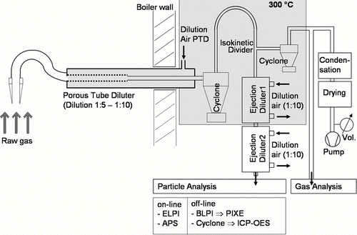
A measurement system was developed to sample and analyze the particle and gas phase of high temperature combustion aerosols up to a particle aerodynamic diameter of approximately 3 mm. The rapid changes of aerosol composition and concentration caused by the inhomogeneous fuel and changing burning conditions were accommodated by a combined measurement of both gas and particle phase and a synchronous measurement of two identical systems at two different positions at the boiler. Based on works reported earlier, an air-cooled dilution probe was designed and adapted to the corrosive composition of the combustion aerosol by use of a silica glass inlet and a ceramic porous tube diluter (PTD). Directly behind the probe, the raw gas is passing a cyclone which precipitates the coarse particles > 25 μm, and is then split into a gas analysis and a particle analysis branch. The particle branch, after further dilution and cooling to ambient temperature, is split for a simultaneous analysis by an APS and a low pressure impactor (ELPI or BLPI). The whole sampling line is conditioned to 300°C until final dilution and cooling to ambient temperature.
The measurement system was employed at different incineration plants between 220°C and 950°C for various experiments, e.g., time resolved concentration analysis during soot blowing cleaning routine. The mass concentration balance, including the content of the inlet, achieved a 92% match of the total slag mass balance of the investigated plant.
INTRODUCTION
The boilers of municipal solid waste incineration plants (MSI) often exhibit high corrosion rates, primarily at the first superheater packages at raw gas temperatures of approximately 480°C and surface temperatures of the superheater tubes of approximately 430°C. The corrosion is caused by high temperature chlorine corrosion, which takes place in presence of alkaline and earth alkaline chlorine compounds at temperatures above 400°C. Corrosion rates, however, strongly vary between plants of similar construction and waste mixture, a phenomenon which is still under investigation (CitationSchroer and Konys 2002). As deposited material is supposed to play a major role in exposing metal surfaces inside the boiler to corrosive substances, the particulate matter of the raw gas was analyzed on its almost complete way through the boiler at temperatures from 950°C to 250°C, and a mass balance was generated.
For investigation of the raw gas, a variety of different sampling methods has been reported meanwhile. For certain questions, particles favorably should be collected in-stack, e.g., on filters (CitationSpiegel 2006), with in-stack cyclones (CitationLind 1999), or with in-stack impactors, which are able to collect the fine fraction of the aerosol in several size fractions at temperatures up to 800°C (CitationDixkens and Fissan 1995) or 1000°C (CitationBrunner 2006) inside the boiler.
If corrosive effects are investigated, however, it has to be taken into account that the flue gas components, particulate and gaseous phase, are subject to processes like nucleation and condensation of volatile gas compounds or vapors like alkali or heavy metal chlorides and coagulation of particles (CitationMikkanen 2000) during their passage through the boiler, influencing the particles' deposition and adhesion properties. Additionally, the corrosive impact of the particles is reduced by sulphation of the particles' chlorine content during the flight, driven by sulphur (SO2/SO3) from the gas phase (CitationChristensen et al. 1998). Both properties can only be determined in the actual state of the raw gas, if it is rapidly diluted and cooled, so that particle collisions and chemical reactions are suppressed as far as possible. For this off-stack method a sample stream has to be transferred from the boiler to the respective off-stack measurement instruments, to generate high resolution data concerning size-fractionated number and mass concentration and to achieve a chemical snapshot.
Various high-temperature sampling systems have been utilized by several groups so far. A method commonly used is to suck the raw gas through a temperature resistant, sometimes cooled (quartz) tube (CitationEnders et al. 2000; CitationChristmann 1999) and dilute the sample at the end of the sampling line, e.g. by ejection diluters (CitationFerge et al. 2004; CitationZimmermann et al. 2000). To reduce physical changes (e.g., condensation, coagulation) of the aerosol particles inside the probe, rapid dilution was applied in the probe body. However, secondary effects like nucleation and dependence of the particle size distribution on the dilution rate or temperature were reported (CitationCiezki and Schwein 1996; CitationKassmann et al. 1997; CitationLipsky et al. 2002, Citation2004). Lind et al. and Mikkanen et al. profoundly investigated combustion aerosols and studied dilution techniques inside various types of sampling probes (CitationLind, 1999; CitationMikkanen et al. 1999; CitationLind et al. 1999, Citation2000). They used a quench probe at raw gas temperatures of 900°C and 150°C, diluting and cooling the gas directly at the inlet by a factor of 10 and by 105°C/s, thus shifting nucleation effects towards particle size regions out of their measured ranges. Another approach was to equip the inlet head with a central size selecting impactor plate that should precipitate particles larger than 10 μ m. Later, a cooled probe with a metal porous tube diluter (PTD) was introduced. Through the PTD, the dilution gas was injected to the sample flow to minimize artifacts caused by condensation or coagulation. This PTD probe is commercially introduced; meanwhile, however, nucleation was again observed (CitationMikkanen 2000; CitationPyykönen et al. 2007). In 2001, Mikkanen implemented a “settling probe,” which collected coarse particles at the bottom of a settling chamber at the end of the probe, after the sample was diluted, cooled, and decelerated to laminar conditions (CitationMikkanen et al. 2001). The drawback of this method is the risk of mixing, interaction and diffusive fractionation of the particle sizes.
Dilution techniques for analysis of exhaust aerosols (dilution tunnel, ejector diluter, PTD, filtration diluter, and rotating disk diluter) were systematically compared by CitationTurrek (2004), who concluded that the most neutral behavior was exhibited by the dilution tunnel—which tends to nucleation and condensation—and by the ejector diluter, which showed a 30% reduction of particle concentration in comparison with the dilution tunnel.
In summary, it appears to be unavoidable that the sample is somehow affected by the sampling. Therefore it is decisive that for every distinct question concerning aerosol properties the most appropriate sampling method has to be selected (CitationJiménez and Ballaster 2005).
EXPERIMENTAL
Based on the experiences reported in the literature, a measurement system with an air-cooled PTD probe was constructed with a cyclone depositing the coarse particle fraction and an ejection dilution cascade that finally conditioned the sample of the particle analysis branch. To enable the sample flow to pass the cyclone without disturbance by previous division, a self-constructed cyclone was used. Not until after the cyclone, the sample flow was isokinetically divided into gas and particle analysis branch.
Particle Measurement Instruments
Particles from 30 nm to 3 mm (aerodynamic diameter) were sampled off-stack, size fractionated, and chemically analyzed. Additionally, acid components of the gas phase were analyzed.
The fine particle size fraction from 30 nm to 10 μ m was measured online with an ELPI (Electrical Low Pressure Impactor, Dekati Oy, Finland; sample flow rate: 30 l/min, bare stage) in its standard 12 stage configuration. For analysis of the particle size distribution up to 20 μ m, an APS (Aerodynamic Particle Sizer, Model 3320, TSI Inc., Minnesota, USA; sample flow rate: 5 l/min) was used. Its measuring range starts at an aerodynamic diameter of approximately 0.8 μ m, so a sufficient overlap with the ELPI range was assured.
In addition to the ELPI, a Berner type low pressure impactor (BLPI, Hauke Ges.m.b.H., Austria; sample flow rate: 30 l/min) was employed for chemical analysis of the particles, as the applied PIXE (Proton-Induced X-Ray Emission) routine was optimized to foil substrates of this size and shape. It provides a particle size fractionation from 63 nm to 10 μ m, divided into 8 logarithmically ordered size fractions. The BLPI was integrated into each measurement session for a 20 min measurement phase. Greased 8 μ m thick polypropylene substrate foils turned out to provide the best analysis quality for PIXE.
The coarse fraction (> 25 μ m) was collected in a self-constructed cyclone () having a 50% cut point of approximately 25 μ m aerodynamic particle diameter at the given flow rate of 30 l/min.
FIG. 1 Sketch of the cyclone, designed for a cutoff point of approximately 25 μ m at a flow rate of 30 l/min.
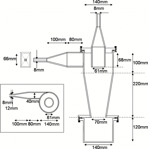
The collected particles were sieved and fractionated into 6 particle size ranges (< 63 μ m, 63–125 μ m, 125–250 μ m, 250–500 μ m, 500–1000 μ m, > 1000 μ m). The fractions were weighted, chemically analyzed with ICP-OES (metals, Si, S) and ion chromatography (anions) and partially characterized regarding their morphology by transmission microscopy.
Sampling System
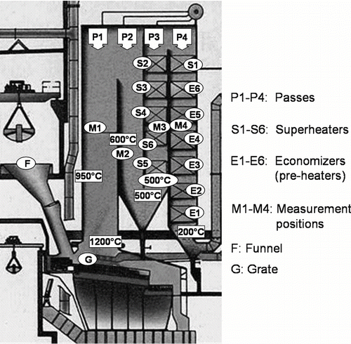
Measurements were performed in the 1st pass at 900°C, in the 2nd pass at 700°C, in the 3rd pass at 500°C, and in the 4th pass at 280°C.
The raw aerosol is isokinetically sampled through swan neck–shaped silica glass inlets (see ). The orifice diameter was chosen between 4 and 8 mm, depending on the flow velocity of the raw gas at the sampling position. Silica glass was used due to its inertness, smooth surface and easy check for cleanness. The inlets were saved after each measurement and their content was chemically analyzed.
Directly behind the inlet, the aerosol is diluted by the PTD by a factor of 5–10 and cooled down to 300°C with preheated air. The whole path through the sampling system is heated to 300°C, what is above the melting point of several eutectic salt mixtures and considerably above the dew point of water and acids.
The PTD is made of a 450 mm long sintered ceramic tube (Al2O3) with a mean diameter of the pores of 1.8 μ m and an open porosity of 28–30%. Porous ceramic was preferred to metal because of its inertness and because the air flow through the porous ceramic has shown to have some advantage in preserving laminar flow conditions (CitationPyykönen et al. 2007; CitationWilson et al. 2004). The sheath flow inside the PTD also positively affected the transportation of the particles. The dilution factor is actively controlled through comparison of the CO2 concentration in the diluted and raw gas sample streams.
The length of the air-cooled probe was set to 145 cm to pass the insulated boiler walls–usually 40 cm thick–and to have flexible access to the main raw gas flow path inside the boiler (). The probe should not exceed a necessary length, as larger particles on their way through the probe tube are susceptible to inertial effects (CitationBaron and Willeke 2001) and gravitational settling what would result in depletion. The outer diameter of the probe is 48 mm to enable the use of the existing standard inlets of the boiler (65 mm diameter). To withstand the boiler temperatures of up to 800°C, heat and sulphur resistant stainless steel (Material 1.4713) was used for the metal parts of the probe body. For sampling at temperatures above 800°C, an additional layer of ceramic isolation tissue was wrapped around the probe tube to protect the steel and to ease the cooling of the probe.
The whole sample path is kept at a tube diameter of 8 mm. The mean aerosol flow rate of 30 l/min thus results in a flow velocity of u = 21 m/s limiting the residence time of the diluted aerosol inside the steel sampling tube to less than 50 ms. A rough calculation of the sink distance of the coarse fraction given by Stokes equation (usink = 8/3 (ρp – ρg)/ρg· g dp/CD]½; ρp: particle density = 2200 kg/m3; ρg: gas density = 700 kg/m3; dp: particle diameter; g: acceleration of gravity = 10 m/s; CD: drag coefficient, for Re > 1000: CD = 0,44) for a 30 μ m particle results in a settling velocity of 0.027 m/s and a settling distance of dsink = 1.35 mm. The resulting Reynolds number Ref (Ref = ρg/η · v · d = 0,7 kg/m3/0,03 mPas · 21; m/s · 0,008 m; η : gas viscosity; d: tube diameter) is 3900 what is below the limit of turbulent flow (Ref = 4000). It can therefore be presumed that the aerosol is only slightly segregated and the coarse particles are not completely deposited on the bottom of the tube.
Directly behind the sampling probe the cyclone is connected and utilized for collection of coarse particles (see ). The close position to the sampling probe does allow employing the cyclone to quantitatively sample the coarse fraction. The cut-off size of 25 μ m was chosen to assure transmission of all particles in the size range analyzed by the subsequent instruments (< 20 μ m).
The raw gas leaves the cyclone through a riser and is then returned to falling flow by a 180° bend with a radius of 200 mm. After 100 mm of straight duct to restore a laminar flow again, the sample gas passes an isokinetic divider which divides the flow into the particle analysis part and the main suction flow. The particulate part is taken from the centre of the flow and proceeds its flow direction (see ). The main flow is sucked through a tube attached at right angle 40 mm behind the inlet of the particulate flow. From the main flow a CO2 measuring branch (to monitor the dilution ratio of the PTD) and the gas analyzing branch is separated, each sucking 2 l/min.
FIG. 4 The setup of the sampling line subsequent to the probe (without isolation) with a sketch of the isokinetic divider separating the sample flow for ELPI/BLPI and APS.
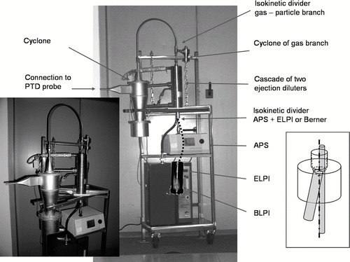
The particulate branch enters a cascade of two ejection dilutors (Palas GmbH), where the dilution air of the first 10 fold dilution is preheated to 300°C, the second 10 fold dilution (see ) cooling the sample gas to approximately ambient temperature. In total, the raw gas is diluted by a factor of approximately 500.
The ejector cascade exit is directly coupled to a self-constructed isokinetic divider for parallel use of the APS (5 l/min) and the ELPI or BLPI (30 l/min, see ). Due to the potentially different concentration of different particle sizes in the cross section of the tube, both branches have access to all coaxial regions. The tube that supplies the coarse particle analysis of up to 20 μ m at the APS (inner diameter 6 mm) is straight prolonged to the APS entrance and connected by a smooth dilatation funnel. The other part of the sample gas is supplying the fine particle analysis of ELPI/BLPI and is coupled into a slightly angled electrically conductive tube with a flange at its end for connection either to the ELPI or BLPI.
All tubes except the silica glass inlet and the ceramic porous tube are made of stainless steel to minimize corrosion and to prevent electrostatic precipitation of charged particles. The inner tube of the probe was changed before each measurement campaign because of slight corrosion of the steel between the measurement campaigns.
For the setup a rack (see ) was constructed to keep all components in a fixed and reasonable position to each other. The arm holding the cyclone rotates about the ejector centre to allow easy connecting or disconnecting the fixed probe to the fixed sampling line. The rack itself is mounted to an outer rack allowing to adjust the docking height of the probe position from approximately 80 cm to 200 cm without changing the system.
As the fuel composition changes in short and long term (waste composition, fire size, operational changes, changes in the performance of the boiler due to its running time, etc.), the aerosol was measured with two identical measurement systems in parallel each time, one at the reference measuring point (2nd pass) and one at the migrating measuring point, respectively, so that the changes of the reference point could be used as an indicator for the current state of the raw gas. A measurement lasted for approximately 35 min, including a measurement phase of the BLPI of 20 min. The measurement system was used in five measurement campaigns over a period of more than three years, while its current configuration was used for the last 3 campaigns.
Reference MSI Plant
In general, the boiler of a MSI has various functions: Primarily, the solid waste is burned on a grate to crack hazardous components and to generate an inert slack which can be dumped. Behind the hot grate zone, the thermal energy content of the produced raw gas is transferred to a water circuit, e.g., by heat radiation to the boiler walls in the first pass and by convection to heat exchanger tubes in the following passes. The steam (Reference MSI: 435°C at 65 bars) is used for power generation systems then. The reference plant has an annual operational capacity of 150,000 tons of municipal waste, operating with three lines (7.6 tons waste per hour and per line) each equipped with a forward-acting reciprocating grate, a counter-current combustion and a typical 4 vertical pass boiler (see ). The front superheater packages (5) and (6) are placed, as usual, at the beginning of the 3rd pass. Based on the plant's records, the total annual amount of dust leaving the grate is approximately 915 t, of which roughly 100 t are deposited on the first two superheater packages.
RESULTS
The particle transmission properties of the measurement system were tested under laboratory conditions with a reference powder (DMT ISO 12103 A2 fine test dust) at ambient temperature. The powder includes particles up to 80 μ m, with a maximum at 20 μ m and a bulk density of 0.9. Although these particles were of comparable sizes to those to be expected in combustion aerosols, the tests were of limited significance only, as the powder formed huge deposits inside the PTD and the sampling lines which was not observed during the real measurements. These differences can be explained by a different particle size distribution and different properties of the coarse fraction.
For the reference MSI plant, the mean total dust mass balance of the particulate matter of the raw gas, resulting from the sum of all sampling components and the determinable losses of the system is depicted in . The total mass concentration is 3.21 g/m3 in the 1st pass which then steadily decreases from 2.99 g/m3 in the 2nd pass to 2.64 g/m3 in the 3rd and 2.08 g/m3 in the 4th pass. These figures are including approximately 5% losses found by deposits inside the sampling system, such as on the tube walls or at the isokinetic dividers, which were randomly collected and weighted. The portion of deposits in the inlet decreases from pass to pass to a finally negligible fraction of 1% in the 4th pass. Moreover, the general reduction of the total mass concentration along the passes is only reflected by the inlet content, whereas all other sampling components do not exhibit a steady reduction.
FIG. 6 Total mass concentration of the particulate matter of the raw gas of each of the four passes, yielded by adding all measured data and loss processes (all figures standardized to NTP conditions).
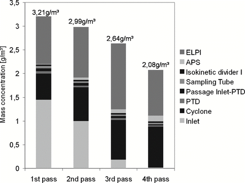
Based on the total mass concentration of the measurements, the total annual amount of dust was calculated by using the documented operational data of the MSI line. Given a mean air volume of 4,500 Nm3 per ton of waste, a mean charge of 7.25 t waste/h and 7,490 annual operating hours of the measured line, the annual total dust mass of the line is calculated to 840 t/a. The actual recorded amount of slag the MSI line accumulates every year inside the boiler is 915 t/a, what means a deviation of 8% of the experimental data.
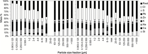
The chemical analysis of the particulate phase was divided into 14 particle size fractions plus the non-size-fractionated analysis of the inlet (see ). The fine fraction (< 1 μ m) mainly consists of secondary generated salt particles, either KCl or NaCl. The coarse fraction (> 20 μ m) has a high portion of primary particles from the grate like ashes, calcium and silica. The middle-sized fraction (1–20 μ m) also chemically intersects these two groups. Heavy metals (Pb, Zn) are more present in the fine fraction, indicating that their oxides act as condensation nuclei for the secondary particles (CitationJoeller 2008). The sulphation of the particles during their flight converted approximately 20% of the chlorine content of the particles to sulphate by the gas phase constituents SO2 and SO3, what mainly affects the fine fraction and primarily takes place at temperatures above 750°C.
FIG. 7 Chemical composition of all size fractions (in micrometers) of 1st (left) and 3rd pass (right). Columns 1–8 shows the composition of the BLPI cascade, column 9 the composition of the inlet and columns 10–15 the composition of the sieved fractions of the cyclone. The so-called “Rest” is the sum of present minor elements (like titanium, bromine, etc.) and the oxygen of the oxides of the shown elements.
Each mass concentration distribution curve is achieved by combining the data of the three measurement instruments ELPI (30 nm–1 μ m), APS (1 μ m–20 μ m) and cyclone (20 μ m–2 mm). Whereas the coarse fraction is weighed and the mass concentration thus directly obtained, for the fine and middle fraction, a particle density of approximately 2.2 g/cm3 is assumed, based on own density determinations and in accordance to literature (CitationRistimäki et al. 2002; CitationVirtanen et al. 2004). The particle size distribution of the inlet deposits was estimated by comparing their chemical composition with the chemical composition of linear combinations of the three main particle size groups. The linear combination yielded a maximum correlation coefficient of 0.90 when combining approximately 40% fine fraction (< 1 μ m), 5% middle fraction (1–20 μ m), and 55% of coarse fraction (cyclone content). As this distribution is similar to the mass concentration distribution of the particulate phase measured by the instruments, the inlet content was distributed to the size fractions proportional to their mass concentration.
The resulting size fractionated mean mass concentration distribution of each pass is depicted in . In all passes, a bimodal distribution with a fine mode and a coarse mode is present. From pass to pass the fine mode is increasing in particle size by particle growth, whereas the maximum of the coarse mode is reduced by particle loss due to deposition.
FIG. 8 Mean size fractionated mass concentration distribution of all 4 passes (all figures standardized to NTP conditions).
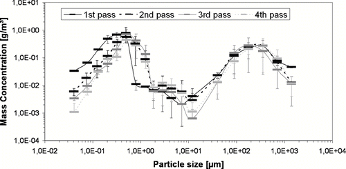
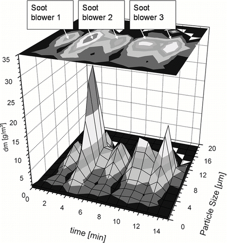
The cleaning procedure of the superheaters, so-called soot blowing, is run every eight hours by injecting high pressure steam from rotating and forth and back moving jets which are placed between the superheater packages. The remobilized particles of the fouling deposits are added to the normal flew gas and can be sampled and analyzed likewise, to get an idea of the removed particle mass and of the chemical processes proceeding on the fouling of the superheater pipes, above all sulphation. Those measurements were performed at the measurement point of the 3rd pass where the aerosol can be sampled which is re-entrained by consecutive run of three soot blowers. As each soot blower is active for only some minutes, employment of both impactor types was not possible, thus besides the APS only the BLPI was used, as more coarse particles dominated and the resuspended matter had to be chemically analyzed. From the measured additional mass concentration, the particulate mass could be roughly estimated which was deposited between two soot blowing runs and then removed by the cleaning. The result—approximately 55 kg—was in the same order of magnitude as the mean amount of ash deposition at that bunker, which was 74 kg per soot blowing interval. The measured chemical composition showed a lower chlorine and higher sulphur content than the usual values of the 3rd pass, what indicated a proceeding sulphation of approximately 30% of the deposits on the superheaters. The time resolved performance of the measurement system reflected by the APS data is given in .
DISCUSSION
The total dust concentration in the 1st pass, derived from the experimental data, shows a standard deviation (SD) of 8%. It was, however, only two times completely measured (2nd pass: n = 8, SD: 31%; 3rd pass: n = 4, SD: 69%; 4th pass: n = 2, SD: 15%). Thus, taking into account the inhomogeneous fuel and fire, the value has a higher uncertainty than reflected by the 92% match of the plant's records. Additionally, 45% of the total mass concentration in the 1st pass is represented by the deposits in the swan neck bend of the inlet. The necessary direction change of the aerosol flow from vertical inside the boiler to horizontal inside the probe is a critical point of the sampling principle, in particular in the 1st and 2nd pass. There a high portion of the particles are sticky and/or fragile agglomerates of different particle size. It is therefore neither possible to separate these particles by use of size fractionating impactors in front of the inlet, as earlier performed to separate the coarse fraction (CitationMikkanen 1999), nor is it a simple task to transfer this fraction through the sampling system even if it could be led around the first bend. For the present, the inlet design was therefore kept the same and the deposits were integrated in all analyses. The mass concentration calculated from the inlet content is distributed to all size fractions according to their mass concentration contribution.
The correlation coefficient of the chemical composition of superheater deposits and the inlet deposit is 0.98, hence significantly higher than the correlation of the inlet content with the size fractions sampled off-stack. Thus, the inlet deposit probably contains a component that is not detected by the analytical instrumentation because it is deposited almost completely in this first bend. Furthermore, the superheater fouling and the inlet deposit might also be of similar composition because of their longer exposition to heat, flue gas atmosphere and particle flow than the particles analyzed by the instruments. Thus, the similarity may be caused by similar, relatively slow chemical reactions of the deposits with, e.g., gas phase components.
The described sampling system utilizes the dilution and cooling principles for hot flue gas described before and adapted them to the more aggressive and unstable raw gas of waste incineration. Consequently, the sampling method has to face similar condensation and nucleation processes of gaseous compounds like alkali chlorides (NaCl, KCl) or heavy metal chlorides (PbCl2, ZnCl2), which will occur due to the low vapor pressure of these compounds. This affects the particle size distribution and the chemical composition, particularly of the sampled fine particle fraction (CitationJensen et al. 2000). Therefore there is a certain difference between the sampled particles and the particles actually present at the respective sampling locations of the plant, particularly at high temperatures. Consequently, the measured and analyzed fine aerosol fraction at 300°C will not be identical with the in-plant particles at high temperatures concerning size distribution as well as chemical composition.
The sampling lines and the final dilution by an ejector dilution cascade affect the sampled aerosol composition by losses due to inertial impaction, thermophoretic effects and diffusion losses (CitationWang 2002), which are difficult to be calculated or exactly experimentally determined. Currently, all models for estimating those effects have to assume laminar conditions, which are tried to be established during the sampling. In reality, however, the aerosol flow also exhibits turbulent phases and inertial deposition interferes with re-entrainment and with transport of the deposited particles in horizontal tubes (CitationAuvinen 2003). Laboratory tests are only of limited significance, either, as the real aerosol can hardly be simulated in the lab. At the current state, therefore it is reasonable—and in accordance with the current recommendations of the VDI (CitationVDI-Richtlinie, 1975)—to construct the sampling tubes on a good practical basis and to observe the real effects during running experiments.
CONCLUSIONS
The sampling system delivered feasible data of both the gas and the particle phase of the waste incinerator raw gas. From the results, the aerosols' changes in size distribution over the four passes of the boiler could be estimated. The inlet content has been included to the particle mass balances and a 92% match of the total dust concentration was achieved. The PTD probe diluted and cooled the sample aerosol in a smooth way which was suitable to reduce particle losses and artifacts like condensation and coagulation inside the probe and the sampling system. To achieve comparability of the measurements despite the heterogeneous fuel and unstable fire, all measurements were synchronously performed by two identical systems at two measurement points. The option of time-resolved analysis, tested at the soot blowing routine, allows to investigate peak mass concentrations of the raw gas and its impact, e.g., on the consecutive cleaning systems like electrostatic precipitators, to investigate cleaning effectiveness or clogging behavior (CitationFerge et al. 2004; CitationMaguhn et al. 2003).
The measurement system, designed for efficient and stable application at MSI boilers, still operates with various conceptual compromises which were discussed and could be addressed for future improvements.
Acknowledgments
This project was funded by the Bayerisches Staatsministerium für Umwelt, Gesundheit und Verbraucherschutz within the scope of the European Regional Development Fund (ERDF).
Christian Deuerling would like to thank Max Buchner Foundation for their kind financial support.
REFERENCES
- Auvinen , A. , Jokiniemi , J. K. and Renvall , T. Online Determination of Aerosol Resuspension in an Internal Tube Flow . Abstracts of the European Aerosol Conference 2003 . Madrid. pp. S109 – S110 . Spain
- Baron , P. A. and Willeke , K. 2001 . Aerosol Measurement. Principles, Techniques and Applications , New York : John Wiley and Sons .
- Brunner , T. 2006 . “ Development of New and Innovative Particle Measurement Devices–High Temperature Low Pressure Impactor ” . In Aerosols and Coarse Fly Ashes in Fixed-Bed Biomass Combustion , Series Edited by: Brunner , T. Vol. 7 , 26 – 39 . Thermal Biomass Utilization, Graz University of Technology .
- Christensen , K. A. , Stenholm , M. and Livbjerg , H. 1998 . The Formation of Submicron Aerosol Particles, HCl and SO2 in Straw-Fired Boilers . J. Aerosol Sci. , 29 : 421 – 444 .
- Christmann , E. 1999 . “ Methoden und Ergebnisse der Gasmesstechnik an der Druckkoh-lenstaubfeuerung ” . In Dorsten. Druckflamm-Seminar, Zeche Zollverein Edited by: Hannes , K. W. 174 – 184 . 17.11.1998
- Ciezki , H. and Schwein , B. Investigation of Gaseous and Solid Reaction Products in a Step Combustor using a Water Cooled Sampling Probe . 32rd Joint Propulsion Conference . July 1–3 1996 , Lake Buena Vista, FL, USA.
- Dixkens , J. and Fissan , H. 1995 . Development of a Ceramic-Cascade-Impactor for Size Classified Particle Sampling in High Pressure- and High Temperature-(HPHT) Processes . Staub—Reinhaltung der Luft , 55 : 283 – 291 .
- Enders , M. , Spiegel , M. , Albrecht , J. and Putnis , A. 2000 . Mineralogical Problems in Advanced Power Systems. The Contribution of Slag and Gaseous Chemical Species to the Fly Ash . Eur. J. Mineral. , 12 : 639 – 650 .
- Ferge , T. , Maguhn , J. , Felber , H. and Zimmermann , R. 2004 . Particle Collection Efficiency and Particle Re-Entrainment of an Electrostatic Precipitator in a Sewage Sludge Incineration Plant . Environ. Sci. Technol. , 38 : 1545 – 1553 .
- Jensen , J. R. , Nielsen , L. B. , Schultz-Møller , C. , Wedel , S. and Livbjerg , H. 2000 . The Nucleation of Aerosols in Flue Gases with a High Content of Alkali—A Laboratory Study . Aerosol Sci. Technol. , 33 : 490 – 509 .
- Jiménez , S. and Ballester , J. 2005 . A Comparative Study of Different Methods for the Sampling of High Temperature Combustion Aerosols . Aerosol Sci. Technol. , 39 : 811 – 821 .
- Joeller , M. 2008 . Modellierung der Bildung und des Verhaltens von Aerosolen in Biomasse-Rostfeuerungen , Thesis Institute of Process Technology, Graz (Austria) University of Technology .
- Kassmann , H. , Amand , L. E. and Leckner , B. 1997 . Secondary Effects in Sampling Ammonia During Measurements in a Circulating Fluidized-Bed Combustor . J. Inst. Energ. , 70 : 95 – 101 .
- Lamminen , E. and Isherwood , H. Effect of Dilution Temperature on Measured Particle Size Distributions from a Coal-Firing Power Plant . Presentation, AAAR .
- Lind , T. 1999 . Ash formation in Circulating Fluidized Bed Combustion of Coal and Solid Biomass , Thesis Helsinki University of Technology (Espoo, Finland) . VTT Publications 387
- Lind , T. , Valmari , T. , Kauppinen , E. , Sfiris , G. , Nilsson , K. and Maenhaut , W. 1999 . Volatilization of the Heavy Metals during Circulating Fluidized Bed Combustion of Forest Residue . Environ. Sci. Technol. , 33 : 496 – 502 .
- Lind , T. , Valmari , T. , Kauppinen , E. , Nilsson , K. , Sfiris , G. and Maenhaut , W. 2000 . Ash Formation Mechanisms During Combustion of Wood in Circulating Fluidized Beds . Proceedings of the Combustion Institute , 28 : 2287 – 2295 .
- Lipsky , E. , Stanier , C. O. , Pandis , S. N. and Robinson , A. L. 2002 . Effects of Sampling Conditions on the Size Distribution of Fine Particulate Matter Emitted from a Pilot-Scale Pulverized-Coal Combustor . Energy Fuels , 16 : 302 – 310 .
- Lipsky , E. M. , Pekney , N. J. Walbert , G. F. 2004 . Effects of Dilution Sampling on Fine Particle Emissions from Pulverized Coal Combustion . Aerosol Sci. Technol. , 38 : 574 – 587 .
- Maguhn , J. , Karg , E. , Kettrup , A. and Zimmermann , R. 2003 . On-Line Analysis of the Size Distribution of Fine and Ultrafine Aerosol Particles in Flue and Stack Gas of a Municipal Waste Incineration Plant. Effects of Dynamic Process Control Measures and Emission Reduction Devices . Environ. Sci. Technol. , 37 : 4761 – 4770 .
- Mikkanen , P. , Kauppinen , E. I. , Pyykönen , J. , Aurela , M. , Vakkilainen , E. K. and Janka , K. 1999 . Alkali Salt Ash Formation in Four Finnish Industrial Recovery Boilers . Energy Fuels , 13 : 778 – 795 .
- Mikkanen , P. 2000 . Fly Ash Particle Formation in Kraft Recovery Boilers , Thesis Technical Research Centre of Finland . Espoo (FIN), VTT Publications 421
- Mikkanen , P. , Jokiniemi , J. K. , Kauppinen , E. I. and Vakkilainen , E. K. 2001 . Coarse Ash Particle Characteristics in a Pulp and Paper Industry Chemical Recovery Boiler . Fuel , 80 : 987 – 999 .
- Pyykönen , J. , Miettinen , M. , Sippula , O. , Leskinen , A. , Raunemaa , T. and Jokiniemi , J. 2007 . Nucleation in a Perforated Tube Diluter . J. Aerosol Sci. , 38 : 172 – 191 .
- Ristimäki , J. , Virtanen , A. , Marjamäki , M. , Rostedt , A. and Keskinen , J. 2002 . On-Line Measurement of Size Distribution and Effective Density of Submicron Aerosol Particles . Aerosol Sci. , 33 : 1541 – 1557 .
- Schroer , C. and Konys , J. 2002 . Rauchgasseitige Hochtemperaturkorrosion in Müllverbren-nungsanlagen Wissenschaftliche Berichte des Forschungszentrums Karlsruhe, FZKA 6695, ISSN 0947-8620
- Spiegel , W. 2006 . “ Analyse Des Rohgases und der Kesselablagerung zur Beurteilung der Ersatzbrennstoffqualität ” . In Energie aus Abfall , Edited by: Thomé-Kozmiensky , K. J. and Beckmann , M. Vol. 1 , 441 – 458 . Neuruppin : TK Verlag .
- Turrek , T. 2004 . Diluting Techniques for Combustion Aerosol Sampling , University of Kuopio, Dept. of Environmental Science . NaPES-Project, Technical Report
- VDI-Richtlinie . 1975 . Messen von Partikeln, Staubmessungen in strömenden Gasen, Gravimetrische Bestimmung der Staubbeladung, Übersicht 2066, Blatt 1
- Virtanen , A. , Ristimäki , J. and Keskinen , J. 2004 . Method for Measuring Effective Density and Fractal Dimension of Aerosol Agglomerates . Aerosol Sci. Technol. , 38 : 437 – 446 .
- Wang , J. , Flagan , R. C. and Seinfeld , J. H. 2002 . Diffusional Losses in Particle Sampling Systems Containing Bends and Elbows . J. Aerosol Sci. , 33 : 843 – 857 .
- Wilson , J. C. , Lafleur , B. G. , Hilbert , H. , Seebaugh , W. R. , Fox , J. , Gesler , D. W. , Brock , C. A. , Huebert , B. J. and Mullen , J. 2004 . Function and Performance of a Low Turbulence Inlet for Sampling Supermicron Particles from Aircraft Platforms . Aerosol Sci. Technol. , 38 : 790 – 802 .
- Zimmermann , R. , Maguhn , J. and Kettrup , A. 2000 . On-Line Analysis of Combustion Aerosols in the State of Formation (900-300°C) at Industrial Incinerators . J. Aerosol Sci. , 31 ( Suppl. 1 ) : 622 – 623 .

