Abstract
The design of a new aerosol sampler, called the blunt-body aerosol sampler (BASE), to sample interstitial particles inside clouds while avoiding the problem of cloud droplet shatter artifacts is introduced. The primary design feature of the inlet is a blunt body that houses an aerosol inlet toward its aft end. The housing is designed to be blunt enough to deflect large cloud particles traveling around the body while being streamlined enough to maintain an attached boundary layer under aircraft flow conditions. The attached flow requirement ensures that shatter particles formed from the impaction of cloud droplets on the blunt body are retained close to the surface of the body. A region of large particle shadow is, thus, created in the aft of the blunt-body housing, where an aerosol inlet can sample interstitial particles in the absence of cloud particles. Computational fluid dynamics (CFD) simulations are used to optimize the shape of the blunt body, and the final sampler design is predicted to sample particles smaller than 2 μm from the freestream while being uninfluenced by cloud droplet shatter particles of the same size. Wind tunnel tests were performed on a prototype model to confirm the attached nature of the boundary layer flow around the blunt body and to establish the size-dependent behavior of shatter particles in the vicinity of the housing. While the experiments provide initial validation of the interstitial inlet design concept, some discrepancies were observed between the wind tunnel tests and CFD predictions, suggesting a need for improvements in simulations, inlet design, and/or test methodology. Initial analyses of field data obtained from the first aircraft deployment of BASE confirm that sampling of shatter-free interstitial aerosol is possible with the inlet, but full performance characterization of BASE will require significant additional aircraft-based experiments under a range of cloud conditions.
Copyright 2013 American Association for Aerosol Research
INTRODUCTION
Aerosol particles influence global climate by directly and indirectly modulating the total solar radiation reaching Earth's surface. The direct aerosol effect relates to the scattering and absorption of solar radiation by atmospheric aerosol particles, while the indirect effect refers to the participation of aerosol particles in forming cloud droplets, which then act to scatter the incoming sunlight. While there is a reasonable understanding of the aerosol direct effect, the contribution of the aerosol indirect effect to the global radiative budget is largely uncertain (Forster et al. Citation2007).
Atmospheric aerosols participate in cloud formation by providing a substrate for heterogeneous nucleation of water. Typically, particles that contain water-soluble material are the ones that are most likely to permit water vapor to condense on them and form cloud droplets (Rogers and Yau 1989). Among the airborne particle population, those that participate in cloud formation are called cloud condensation nuclei (CCN), while the ones that do not form cloud droplets are referred to as interstitial or nonactivated particles (Seinfeld and Pandis Citation2006). The ability of particles to act as CCN depends on their physical and chemical characteristics (Saxena and Hildermann Citation1996; Jennings et al. Citation1997; Forster et al. 2007), and the availability of simple models to predict the CCN fraction and the resultant cloud characteristics in an airmass is critical for accurate modeling of the aerosol indirect effect on global climate.
Data from a wide range of cloud systems are required to help inform the development of comprehensive aerosol-cloud models. Aircraft platforms are the most suitable for obtaining such data, because of their ability to cover large spatial scales and carry a comprehensive payload. Aerosol-cloud measurements from aircraft have typically focused on sampling cloud droplets and evaporating them to determine the nature of the nuclei contributing to their formation. Because of the possible transformation of the nucleated particles during the condensation–evaporation process, it may not always be possible to determine the exact nature of the nuclei from this approach. For complete characterization of aerosol-cloud systems, in addition to cloud droplets, measurement and analysis of interstitial particles is also required. As interstitial particles will generally be unchanged during cloud processing, analysis of these particles provides a more direct basis to understand the relation between aerosol particle properties and their role in cloud formation. A comparison of the measurements of the out-of-cloud aerosol population characteristics with the in-cloud interstitial aerosol characteristics will help establish the particle properties that help or hinder their activation to cloud droplets.
Measurements of in-cloud interstitial particles from aircraft have, however, been problematic because of sample flow contamination with shatter particles that are generated from the breakup of cloud droplets impacting on aerosol inlets. The observation of increased in-cloud condensation nuclei (CN) numbers was initially attributed to the process of bimolecular nucleation of sulfuric acid and water (Hegg et al. Citation1991; Perry and Hobbs Citation1994; Clarke et al. Citation1998), but has since been recognized as an artifact resulting from cloud droplet interaction with aerosol inlets (Weber et al. Citation1998). When cloud particles (liquid droplets, ice, and snow) impact on aerosol inlets or pass through regions of strong velocity gradients, they can breakup, and generate a large number of secondary particles. Some of the small secondary particles generated from cloud particle shatter are sampled into aerosol inlets, resulting in elevated measurements of CN concentrations inside clouds.
Weber et al. (Citation1998) noticed that increased particle counts inside clouds were directly correlated with liquid water content and inversely with inlet diameter and concluded that artifact particles generated from cloud particle shatter were the primary cause of the observed CN enhancement. Shatter generation has been directly observed in visualization experiments performed in icing wind tunnels (Korolev et al. Citation2011), and indirectly determined from analysis of data acquired by different cloud probe designs in the same cloud system (Korolev and Isaac 2005; Korolev et al. Citation2011; McFarquhar et al. Citation2007) and from close examination of images acquired by cloud probes (Korolev and Isaac Citation2005; Korolev et al. Citation2011. In addition, from the analysis of arrival times of particles in the viewing volume of cloud probes, Korolev and Issac (Citation2005) showed that when small particles were observed, they were often in a cluster, suggesting their generation from the shatter of a larger cloud particle at the inlet tip. The interarrival times have since been used as a critical criterion for identifying and removing shatter particle contribution to cloud probe measurements (Korolev and Isaac Citation2005; Field et al. Citation2006; Jensen et al. Citation2009; Korolev et al. Citation2011). The shatter problem is more significant for aerosol measurements because of the similar size ranges of the shatter-artifact and interstitial particles and because flow mixing in the sample tube makes it impossible to employ techniques such as interarrival time investigations to eliminate the shatter contribution to the aerosol signal. As a result, very limited data on interstitial aerosol are available from aircraft platforms (Gillani et al. Citation1995; Schroder and Strom Citation1997; Schroder et al. Citation1998) and even in these studies, the possible contribution of shatter artifacts to the data set is not well known.
For accurate sampling of interstitial particles from aircraft platforms, the design of a new aerosol inlet called the blunt-body aerosol sampler (BASE) is introduced. The design and evaluation of the sampler is based on computational fluid dynamics (CFD) simulations, wind tunnel testing, and flight-testing. The design process, details of CFD simulations, and analysis of the sampler performance are presented here.
BASE: CONCEPT AND CHALLENGES
Design Concept
Central to the BASE design is a blunt-body housing. The role of the blunt body is to trap and deflect large particles that are directed toward it, so as to permit shatter-free interstitial particle sampling in its aft region. Large particles (e.g., cloud/precipitation droplets), because of their significant inertia, will not follow the flow streamlines around the curvature of the blunt body and those in line with the blunt body will either impact on its front area or be deflected out, while those beyond the sweep of the blunt body will pass straight through (Dhaniyala et al. Citation2004). Thus, in the aft of the blunt body will be a region of large particle shadow, where an interstitial aerosol inlet can be located. The principles of this design are similar to that of the ER-2 Football inlet (Fahey et al. Citation1989; Dhaniyala et al. Citation2004).
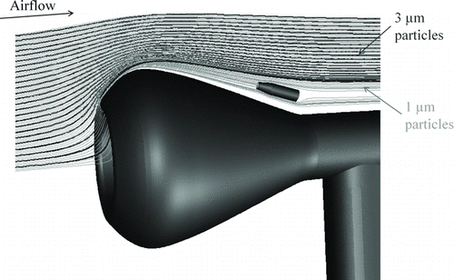
FIG. 1 Design concept of the BASE. The interstitial inlet is located toward the aft of the blunt body housing, below the line of sight of large droplets, and above the region where shatter particles are present. (Color figure available online.)
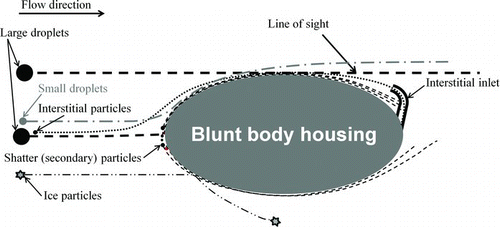
Cloud droplets impacting on the blunt body will either bounce (ice particles) or shatter (liquid droplets and some ice/snow particles) on contact. Particles that bounce will be deflected away from the blunt body, while the small shatter-generated secondary particles will quickly relax to the local flow conditions and follow the streamlines close to the surface of the body (). If the blunt body is designed such that its boundary layer remains attached, then the secondary particles will remain close to the blunt-body surface. Thus, at the aft of the blunt body, in a region between the large particle “line-of-sight” and the edge of the boundary layer, the only particles present will be the small freestream particles, i.e., interstitial particles. A sampling tube located in this region should only sample interstitial particles and be unaffected by cloud droplet shatter.
Challenges
An optimal blunt-body shape must be determined to ensure that a sufficiently broad region of large particle shadow is available. There are several challenges in arriving at an optimal BASE design. If the flow around the blunt body separates, the shatter-generated particles within the boundary layer will mix with freestream particles and contaminate any aerosol sample taken from the aft region of the blunt body. Also, any turbulence in the boundary layer can result in mixing of freestream particles with shatter particles present near the surface of the blunt body. Thus, in designing the blunt body, it is critical that the boundary layer remains attached and is preferably laminar along the entire length of the flow.
A blunt body in flow will usually experience flow separation in the aft region because of adverse pressure gradients in this region (Schlichting et al. 2004). To ensure an attached boundary layer, a variety of techniques can be used, including boundary layer suction, blowing, and moving walls (Schlichting et al. 2004). For boundary layer control in BASE, a flow-suction approach is ideal because this will additionally enable the boundary layer to remain laminar (Huebert et al. Citation2004), preventing turbulent mixing of shatter and freestream particles. In determining an optimal blunt-body shape, however, a conservative design approach was followed, i.e., the body was shaped to have an attached boundary layer upstream of the interstitial inlet even in the absence of any flow suction.
Another potential pathway for artifact particle generation in clouds is the formation and breakup of a liquid film on an inlet surface. When a small cloud droplet (∼<10 μm) impacts on an inlet, it may not have enough energy to breakup, and it may just deposit on the surface and form a liquid film. Also, larger droplets that shatter on impaction may leave behind some of the droplet mass on the surface, resulting in film formation (Mundo et al. Citation1995). As the liquid film negotiates sharp corners or interacts with highly turbulent flows, it may shed small droplets, contaminating aerosol measurements (Lawson and Cooper Citation1990). The use of boundary layer suction in the BASE design will remove the liquid film with the boundary layer flow and prevent film buildup over time. Minimizing the liquid film growth will prevent the formation of surface waves in the film and, thus, their breakup into secondary droplets.
In addition to impaction, cloud droplets can also breakup when they experience strong aerodynamic forces, such as during their acceleration and deceleration (Lane Citation1951; Reitz Citation1987). Aerodynamic droplet breakup can, however, be neglected for the BASE design, because large droplets that are likely to breakup aerodynamically will not reside long enough in the decelerated stagnation region upstream of the blunt body (Tan et al. Citation2005). Thus, only impaction breakup of droplets is considered here for analysis of sampling artifacts.
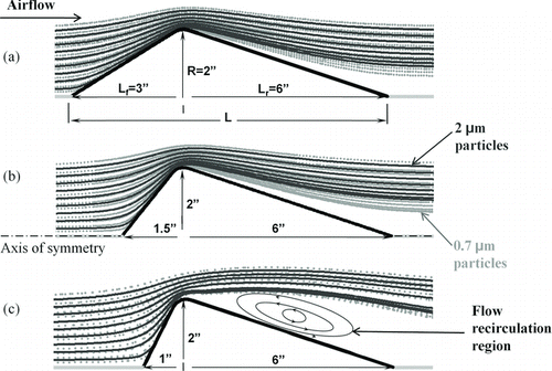
FIG. 2 Particle trajectories around double cone geometries of different aspect ratios. (a) and (b): Particle size separation increases with decreasing front cone chord length. (c) At very short cone chord lengths, flow separation results and size separation region decreases. All dimensions are in inches.
Numerical Simulation as a Design Tool
Computational fluid dynamics modeling was used to optimize the blunt-body shape such that a large enough aft region was available to locate an interstitial inlet. CFD simulations have previously been successfully used in design and analysis of different airborne probes by Dhaniyala et al. (Citation2003), Cain and Ram (Citation1998), Twohey (Citation1998), and Baumgardner and Huebert (Citation1993). The design and analysis of BASE was conducted using the CFD software FLUENT (Version 6.2.3; ANSYS Inc.). The flow around the blunt body was modeled as axisymmetric, compressible flow, using the “coupled” solver option and the k–ω SST turbulence model. The choice of this turbulence model is based on its effectiveness for simulating the turbulent boundary layer characteristics (FLUENT user manual Citation2006), critical for the BASE design. In the k–ω shear stress transport (SST) model, Reynolds-averaged Navier–Stokes equations are solved along with transport equations for the turbulence parameters. In the inner region of the boundary layer, the standard formulation for kinetic energy (k) and the specific dissipation rate (ω) are solved, accounting for Reynolds number and shear flow effects. In the outer region of the boundary layer, the high-Reynolds-number version of the k–ϵ equations is used for turbulent flow simulation (Menter et al. Citation2003). As the initial design of BASE was for deployment on NSF/NCAR's C-130 aircraft, with a particular focus on measurements in young, low-altitude clouds, the inlet simulations were conducted with correspondingly appropriate boundary conditions of freestream velocity 100 ms−1 (Ma = 0.32) and a static pressure of 800 mb. Pressure far-field boundary condition was used at the freestream boundaries of the computational domain and the selection of the computational domain size was based on the dimensions of the model being studied. For a body of chord length L and radius R (), the initial simulations were conducted with the upstream, downstream, and cross-flow boundaries at distances of 5L, 10L, and 20R, respectively, from the edge of the body. About 160,000 computational nodes were used for all body shaping cases. The recommended grid size for enhanced wall treatment (y + ∼ 1) was considered, resulting in a first cell distance of ∼ 17 μm from the wall for these simulations
For this study, cloud droplet sizes were considered to be in the range of 2–50 μm, while the interstitial particles were assumed to be smaller than ∼2 μm. The selection of the lower size limit of cloud droplets as 2 μm is motivated by the detection limit of typical in-situ cloud probes deployed on aircraft (e.g., CDP or FSSP-100). The trajectories of particles in the interstitial size range are calculated using a Lagrangian formulation of the particle transport equation considering the particle Stokes drag, given as:
After the initial body shaping simulations, the final geometry was modeled with a larger computational domain, of size 18L, 22L, and 10R in the upstream, downstream, and cross-flow directions, respectively. The large external domain size was selected to make sure that the flow close to the boundaries was unaffected by the presence of the blunt body in the modeling domain. A multiblock, structured grid was used throughout the domain and the grid was repeatedly refined until the boundary layer flow was well resolved. The final refined mesh case consisted of ∼450,000 nodes. Grid insensitivity of the solutions was confirmed from analysis of the particle sampling efficiencies as a function of grid size. Eddy et al. (Citation2006) suggested that an invariability of particle sampling efficiency with grid refinement is a more stringent requirement for checking adequacy of grid resolution than any insensitivity condition based on fluid flow. For the fully converged solution, the relative continuity residual for the case with highest grid resolution (450,000 nodes) was ∼4 × 10⁻⁶.
Shaping the Blunt Body Housing
For effective deflection of all particles, larger than ∼2 μm from the aft region, the fore-end of the body must be blunt. To maintain attached flow around the body, its geometry, particularly along the aft-end, must be streamlined. To optimize the contrasting needs of the fore and aft ends of the blunt-body design, a parametric study was conducted using a double cone profile, i.e., an axisymmetric body with two cones attached at their common base (). In the parametric simulation study, the geometry ratios (i.e., radius to chord length ratios) of the two cones were varied and the corresponding flow fields and particle trajectories were calculated and analyzed.
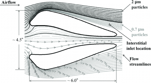
FIG. 3 The final shape of the BASE blunt body housing. Particle trajectories for 2 μm and 0.7 μm are shown on the top half of the geometry and flow streamlines are shown in the lower half. The location of the interstitial inlet is indicated with a line segment.
From initial simulations, it was determined that a geometry ratio of 1:3 (R:L r in ) was the smallest value for which the flow remained attached to the body. At smaller ratios, flow separation was observed almost independent of the front cone size. For optimizing the front cone dimensions, simulation results of flow and particle trajectories were analyzed to determine the smallest particle size that could be deflected sufficiently away from the aft region, while avoiding flow separation. Increasing the radius-to-chord length ratio of the front cone increased the spatial separation of particles of different sizes, as illustrated for 0.7 and 2.0 μm diameter particles in . At geometry ratios greater than 1:1, however, flow separation was observed () and hence this ratio was assumed as the optimal one for the front cone.
The final blunt-body shape was determined from a series of simulations starting with the optimal double cone dimensions and then sequentially smoothing the geometry based on near-wall streamlines to ensure recirculation-free, attached flow conditions. In addition, as the region of large-particle shadow is essentially determined by the maximum thickness of the body (R in ) and not the exact shape of the frontal area, in the final BASE design, the front face of the blunt body was hollowed out to reduce the impaction surface area for large particles, and minimize shatter particle generation. The final profile of the blunt body housing is shown in .
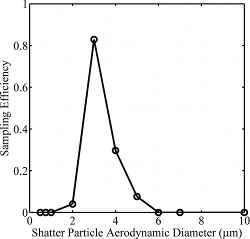
The presence of the interstitial inlet and the strut connecting the housing to the aircraft, introduce three-dimensionality to the BASE geometry. Considering the 3D geometry, the final sampling characteristics of the inlet were determined from 3-D flow simulations. The interstitial inlet was represented by a ¼″ inlet tube, located where particles larger than 3 μm are completely absent and 1 μm diameter particles and smaller are present at their freestream concentrations (). The orientation of the inlet tube was adjusted until it was aligned with the local flow streamlines, so as to minimize any flow recirculation within the inlet tube because of flow misalignment (Huebert et al. Citation1990). A sample flow of 6 slpm was considered in the 3D simulations, resulting in subisokinetic operation of the inlet. As the particles of interest are largely in the submicrometer size range, the concentration enhancement of these particles because of anisokinetic sampling is minimal.
For 3D simulations, the particle sampling efficiencies were calculated by comparison of flow rates and trajectories crossing through two control surfaces, one at the interstitial inlet entrance and another far upstream (a simplified version of the method described in Ram and Cain Citation1998). A total of 6400 particles were distributed evenly in an upstream control surface area of 0.76 cm × 1.27 cm located at about 1.01 m upstream of the blunt body. The location of the injection surface was adjusted to ensure that the injected bundle of particle trajectories encompassed the flow around the interstitial inlet. The sampling efficiency as a function of particle aerodynamic diameter and Stokes number is shown in . As the flows decelerate, change direction, and accelerate around the blunt body, particles of different sizes, and thus relaxation times, respond differently to these variations in flow velocities. Particles with large Stokes numbers (> ∼1; considering the blunt-body dimensions) will be largely uninfluenced by changes in the flow field, and will be inertially captured on the blunt body or pass straight through. Particles with small Stokes numbers (< ∼0.01) will quickly relax to the local flow conditions and largely follow the curvature of the blunt body and be present at the inlet region in the same concentration as that in the freestream. Particles in the intermediate Stokes number range (∼0.01–1) will be displaced from their streamlines as they go around the blunt body, resulting in a complex size-dependent particle concentration field in the aft region of the blunt body. For the C-130 conditions considered here, particles in the diameter range of 1–3 μm are in the intermediate Stokes number regime, and these particles are inertially focused into a narrow set of streamlines as they navigate around the curvature of the blunt body and are, thus, seen to be at enhanced concentrations relative to that in the freestream at the inlet location. This observation is consistent with previous reports of blunt-body-induced enhancement of particles over a narrow size range (de la Mora and Rosner Citation1981; King Citation1984; Geller et al. Citation1993; Dhaniyala et al. Citation2004; Healy and Young Citation2005).
FIG. 5 Sampling efficiency of the inlet as function of aerodynamic diameter and Stokes number. The Stokes number is calculated based on freestream velocity and blunt body diameter.
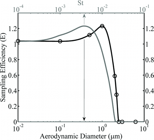
The sampling efficiencies of submicrometer particles calculated from 3D simulations at the highest grid resolution are seen to be slightly (∼6%) larger than the expected value of 1. This slight overestimation is possibly because the computational grids along the path of the sampled particles are not sufficiently fine, but the current calculations are limited by the available computational resources.
Shatter Modeling
Modeling the possible shatter particle contribution to the inlet sample is complicated by our limited ability to predict the distribution of sizes and velocities of the secondary particles generated from droplet breakup. Existing impaction droplet breakup models (O’Rourke and Amsden Citation2000) are largely based on experimental data acquired from low-speed impaction of droplets, and, therefore, their applicability for analysis of cloud droplet shatter on high-speed aircraft samplers is not clear. Also, there are no existing models for the prediction of the products of high-speed impaction of ice/snow particles on solid surfaces. Considering these limitations of shatter models, the BASE was designed using a conservative shatter modeling approach. In this approach, particles in the size range of up to 10 μm, were “injected” at the surface of the blunt body housing with a range of normal velocities. This injection represents all possible sizes and velocities of secondary particles generated from the shatter of cloud droplets at different locations on the BASE blunt body. Analysis of trajectories of these injected particles indicated that shatter particles smaller than 2 μm remain close to the surface of the blunt body even for injection velocities as large as 100 ms−1 (i.e., for elastic bounce from the surface) and they do not enter the interstitial inlet. For the case of high injection velocities (100 ms−1), shatter particles in the size range of 2–6 μm are likely to be present at the inlet location ().
WIND TUNNEL TESTING
Prior to aircraft deployment of BASE, preliminary testing of the validity of the sampler design concept was made with wind tunnel experiments. Wind tunnel measurements with BASE were conducted in Clarkson's high-speed tunnel, which has a rectangular test section of dimensions: 3 feet by 4 feet; with a maximum test section velocity of 70 m s−1. From initial tests, it was determined that aerosol measurements in the tunnel were best conducted with wind speeds less than 40 m s−1. For the C-130 flight conditions considered in flow modeling, the Reynolds number based on the chord length of the blunt body (L in ) is 746,000. To ensure Reynolds number consistency, the size of the wind tunnel test model was appropriately scaled up. A stereolithography technique was used to fabricate the scaled-up test model. Initial tuft flow visualization tests were performed in the tunnel for a range of airspeeds from 16 to 50 m s−1. For airspeeds from 30 to 50 m s−1, i.e., over a Reynolds number range of 385,000 to 641,000, the flow was observed to remain attached over the blunt body surface, with the general flow pattern being independent of airspeed/Reynolds number. Thus, considering the constraints of aerosol measurements, all subsequent wind tunnel tests were conducted at a wind speed of 40 m s−1.
The primary goal of the wind tunnel tests was to validate the key design features of BASE, i.e., separation of shatter particles from freestream particles of the same size in the aft region of the blunt body. At a tunnel wind speed of 40 m s−1, however, generation of shatter particles at sufficient concentrations was not possible. Instead, similar to the modeling approach, the generation of shatter particles was “simulated” by injecting particles at the surface of the blunt body housing. Particles over a broad size range were injected from a slit upstream of the interstitial inlet to represent different impaction and generation possibilities. This testing concept is shown in .
FIG. 7 The schematic diagram of the wind tunnel experimental setup used for initial validation of the BASE design concept.
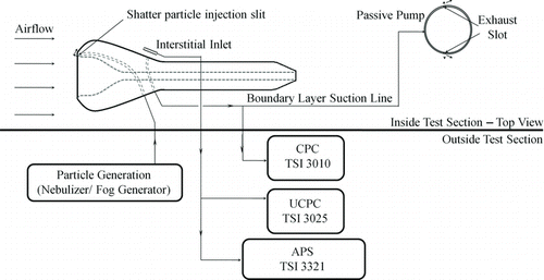
Two particle generation systems were used to generate the “shatter” particles. In the first system, shatter particles were generated by the nebulization of 5% DOS (DiOctyl Sebacate) solution and the size distribution of the generated particles was independently obtained using an aerodynamic particle sizer (APS, TSI 3321; TSI, Shoreview, MI, USA) as well as a high-sensitivity laser spectrometer (HSLAS; Particle Measurement Systems Inc., Boulder, CO, USA). The particle sizes were determined to have a log-normal distribution with the mode at ∼200 nm with negligible particle concentration in sizes larger than 2 μm. Only the tail of the distribution was, thus, in the detection range of the APS instrument. In the second system, particles were generated using a Rosco Fog generator and injected at the body surface as before. The particles from the Rosco fog generator encompassed a broader size range, with particles extending to the coarse mode (2.5–10 μm size range). A significant difference in the operation of the two “shatter systems” is the velocity with which the shatter particles were injected at the inlet surface. In the first system, the nebulized particles are sent at a controlled low flow rate and are thus injected with small velocities (< ∼2 m s−1). In the second system, the fog particles are passively sampled from a large volume, with the injection flow rates primarily driven by the low pressure in the tunnel, resulting in high injection flow velocities of these particles (∼20–40 m s−1).
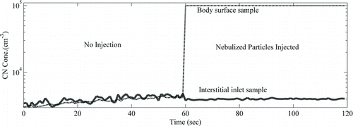
FIG. 8 Wind tunnel measurements of total number concentrations in the BASE boundary layer and interstitial inlet sample flow for cases of: no shatter particle injection (0–60 s) and nebulized shatter particle injection (60–120 s).
From initial flow visualization tests, it was observed that boundary layer suction was necessary to maintain attached flow over the blunt body and subsequently all tests were conducted with the boundary layer suction turned on. For boundary layer suction, a passive pump was used. The passive pump was a cylinder with two slots at ∼80° from the front stagnation line, where the static pressure is expected to be at its minimum, providing a substantial driving force for suction flow. Particle measurements were made with an APS and a pair of condensation particle counters (CPCs) from two sample flows: one from the boundary layer and another from the interstitial inlet. The boundary layer particle concentrations were obtained by subsampling from the boundary layer suction flow. The total number concentrations in the interstitial inlet sample were measured using a TSI 3010 with a lower detection size of 10 nm, while the TSI 3025 CPC with a lower detection size of 3 nm was used for measuring the total particle concentration in the boundary layer flow. The upper size limit of both the CPCs is > ∼3 μm. The differences in the CPC cut sizes were not seen to be important because a very small fraction of particles generated during this study were in the size range of 3–10 nm.
RESULTS
Nebulized Particle Injection
Initial measurements were made without injection of any “shatter” particles and under these conditions, both the boundary layer and interstitial inlet were sampling the background particle concentrations in the inlet. For these test conditions, as expected, the total particle concentration from the two sample flows (interstitial inlet and boundary layer flow) were seen to be well matched (). After injection of nebulized particles, the total number concentration in the boundary layer flow increased by a factor of ∼20, to values over 100,000 cm−3, while the particle number concentrations in the interstitial inlet were largely unchanged (∼4000 cm−3).
After the injection of nebulized particles, the total number concentrations in the size range of 0.5–20 μm, as measured by the APS, was ∼3600 cm−3 in the boundary layer flow sample and ∼100 cm−3 in the interstitial inlet sample (). In comparison, for the no-injection case, the total APS particle concentration from the interstitial inlet sample was ∼10 cm−3. The increase in particle concentration in the interstitial sample after the injection of nebulized particles is not evident in the total CPC particle concentration measurements () because of small magnitude of the increase, ∼100 cm−3, relative to the total particle concentration of 4000 cm−3.
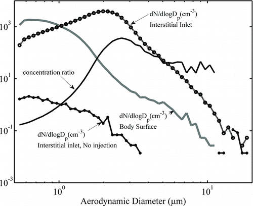
FIG. 9 Wind tunnel measurements of particle size distribution in the BASE boundary layer and interstitial inlet sample flow for cases of: no shatter particle injection and nebulized shatter particle injection.
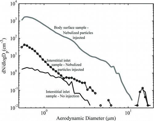
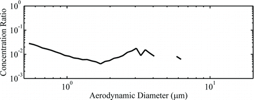
From the results of the nebulized shatter particle injection tests, it can be concluded that: (1) for the low-velocity injection case, the submicrometer shatter particles largely remain close to the surface of the blunt body, thus, suggesting that the boundary layer is largely attached; and (2) there is a small contribution of shatter particles (∼1%) in the interstitial inlet sample, even in the submicrometer particle size range, contrary to the results of the CFD simulations (). To further analyze the shatter particle contribution to the inlet sample, the ratio of the APS size distributions obtained from the two samples is shown in . The concentration ratio is seen to be mostly small and relatively constant (∼0.01) for most sizes, with a small decrease in the shatter contribution with increasing particle size. The relatively size-independent concentration ratio is because particles are well mixed in the boundary layer and turbulent dispersion of these particles can result in a small fraction of these particles mixing with the freestream, resulting in their observation at the inlet location. The turbulent nature of the BASE boundary layer is particularly enhanced in our tests because of: injection of flow into the boundary layer; and relative rough surfaces of the stereolithography model. As the flight version of BASE will not involve any injected flows and should have smoother surfaces, the turbulent dispersion problem should not be of concern for the aircraft version of the inlet. Also, it is expected that the on-board aircraft venturi pump on NCAR's C-130 aircraft will provide much higher boundary layer suction flow than possible in our wind tunnel tests, which should additionally help in maintaining a laminar boundary layer upstream of the inlet location.
Fog Particle Injection
When fog particles were injected at the surface of the blunt body, the particle concentrations of both the interstitial inlet and the boundary layer samples were significantly increased (). A comparison of the results of the fog particle injection case with that of the nebulized case shows that concentration ratios (inlet to bluntbody surface concentration) at all sizes are significantly higher for the fog particle injection case. Also, the concentration ratio is seen to be strongly size-dependent. For submicrometer particles, the ratios are less than 1 and decreasing with decreasing sizes. For particles larger than 1 μm, the concentration ratio is seen to be significantly greater than 1, with a maxima in the ratio corresponding to particle sizes in the range of 2–3 μm. The very different results with the fog particles compared to the nebulized particles can primarily be attributed to the different injection velocities for the two cases. For the case of fog particles, because of their injection at high velocity, larger particles are inertially transported to regions outside the boundary layer flow. Thus, particles larger than 1 μm are largely only present at the inlet location and not at the boundary surface. Also, the higher velocity of the injection flow causes a greater disturbance to the boundary layer flow and hence enhances the mixing of particles with the freestream. This enhanced mixing causes the concentration ratio of submicrometer particles to be higher for the fog injection case than the nebulized case.
A direct comparison of the wind tunnel results with CFD predictions is complicated by the different flow and particle velocities for the two cases and the significant role of turbulent dispersion in the wind tunnel tests. However, analysis of wind tunnel results suggest that, in the absence of turbulent dispersion, submicrometer shatter particles should not contaminate the inlet sample, and consistent with the CFD predictions () shatter particles larger than 2 μm will escape the BASE boundary layer and be present in the interstitial inlet sample. Thus, shatter-free interstitial measurements with BASE should be possible if only small cloud droplets are present, but the presence of large cloud droplets or drizzle may result in the generation of large shatter particles and contamination of interstitial measurements.
FLIGHT TESTING
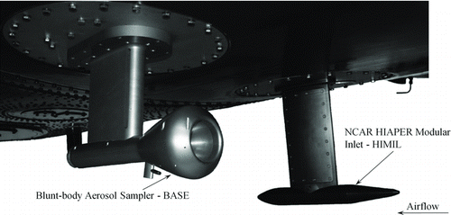
After the initial tests in the wind tunnel, an aircraft version of BASE was fabricated and flown on the NSF/NCAR C-130 aircraft as part of the PLOWS campaign (2009–2010). During this campaign, the inlet was instrumented to characterize its flow field and determine its particle sampling characteristics. The performance of BASE is compared against a conventional forward-facing, diffuser-type aerosol inlet, called the HIAPER modular inlet (HIMIL) that was designed at the NCAR and is typically flown on NCAR aircrafts for measurement of total concentration of condensation nuclei (CN). A picture of BASE installed on the NSF/NCAR C-130 aircraft during the PLOWS campaign (2009–2010) along with the HIMIL inlet is shown in .
FIG. 13 Performance of the HIMIL and BASE inlets on NSF/NCAR C-130 aircraft in a drizzle-free cloud penetration case.
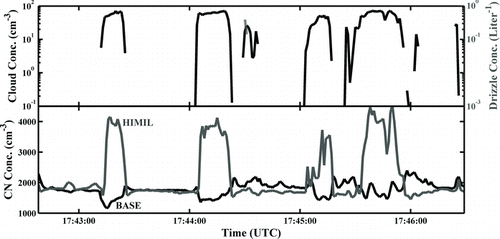
For preliminary field characterization of the BASE performance inside and outside clouds, measurements of total CN concentrations made from the inlets with two CPCs (TSI 3010 for BASE and low pressure TSI 3786 for HIMIL) are analyzed during a short time period as shown in . For this analyzed case, the CN total concentration measurements from the inlets were well matched outside clouds, suggesting that most of the sample particles were submicrometer, a size range that both inlets sample representatively. On entering clouds, the total particle concentrations from the HIMIL are seen to increase dramatically as typically observed for traditional aerosol inlets (Weber et al. Citation1998), while the BASE CN concentrations are depleted relative to the out-of-cloud aerosol concentrations. The HIMIL measurements of high CN concentrations in clouds, is consistent with droplet shatter on typical forward-facing aerosol inlets. Analysis of this preliminary data set suggests that the BASE design does indeed enable shatter artifact-free sampling from aircraft platforms. Further analysis of the BASE field data is required to fully characterize the performance of BASE under a range of cloud and aircraft conditions and results from such an analysis will be presented in future publications.
CONCLUSION
A new aerosol sampler, called BASE, was developed for accurate sampling of aerosol inside and outside cloud systems. Special emphasis in designing the sampler was to avoid shatter artifacts created from the impaction and breakup of cloud particles when they interact with the inlet body. Central to the sampler design is a blunt body housing which acts to shield the interstitial aerosol inlet from the direct impaction of cloud particles and directs any shatter particles generated on the blunt body away from the inlet sample flow. The optimization of the inlet design was achieved through a series of CFD simulations. The interaction of shatter-generated particles with the sampler flow field was modeled using a simple conservative approach and the simulation results suggest that shatter particles smaller than ∼2 μm will not be present in the interstitial inlet of BASE. A prototype was tested in a wind tunnel and the performance of the inlet in the presence of shatter particles was investigated. While the analyses of wind tunnel results were somewhat complicated by the turbulent dispersion of particles in the boundary layer, the results did suggest that, under low-velocity injection of particles relatively contamination-free interstitial measurements are possible. Under high-velocity injection, size-dependent behavior of shatter particles was noticed, largely consistent with CFD predictions. Initial aircraft test results do suggest that the BASE interstitial inlet can provide shatter-free sampling of interstitial aerosol in warm, drizzle-free clouds. The development of BASE and its performance validation is a significant advance for aircraft-based aerosol sampling.
For effective deployment of BASE for atmospheric studies, significant additional testing is required to fully establish its performance. Wind-tunnel-based shatter experiments must be conducted with techniques that do not require the use of injection flow. Also, numerical modeling and wind-tunnel results both show that the locations of the shatter particles larger than 1 μm at the inlet location are strongly dependent on their ejection velocities from the blunt-body surface. The ability to predict the velocity of the shatter particles is, thus, critical for further optimizing the inlet design and accurately predicting its sampling performance. To fully establish the performance characteristics of BASE, extensive aircraft-based testing will be required. Some of the necessary tests include: sampling efficiency tests by comparison with forward-facing probes under out-of-cloud sampling conditions; comparison of CN measurements of cloud-base aerosol and in-cloud interstitial aerosol with BASE; and determination of the inlet response as a function of cloud droplet properties. Field data obtained from such tests, should help establish the performance of the inlet and improve its design.
Acknowledgments
The authors would like to thank the NSF for financial support (AGS-0548036) and Douglas Leonard for assistance with wind tunnel experiments.
REFERENCES
- Baumgardner , D. and Huebert , B. 1993 . The Airborne Aerosol Inlet Workshop: Meeting Report . J. Aerosol Sci. , 24 ( 6 ) : 835 – 846 .
- Cain , S. A. and Ram , M. 1998 . Numerical Simulation Studies of the Turbulent Airflow Through a Shrouded Airborne Aerosol Sampling Probe and Estimation of the Minimum Sampler Transmission Efficiency . J. Aersol Sci. , 9 ( 29 ) : 1145 – 1156 .
- Clarke , A. , Varner , J. , Eisele , F. , Mauldin , R. , Tanner , D. and Litchy , M. 1998 . Particle Production in the Remote Marine Stmosphere: Cloud Outflow and Subsidence During ACE1 . J. Geophys. Res. , 103 : 16397 – 16409 .
- de la Mora , F. J. and Rosner , D. E. 1981 . Inertial Deposition of Particles Revisited and Extended: Eulerian Approach to a Traditionally Lagrangian Problem . Physicochem. Hydrodyn. , 2 : 1 – 21 .
- Dhaniyala , S. , Flagan , R. C. , McKinney , K. A. and Wennberg , P. O. 2003 . Novel Aerosol/Gas Inlet for Aircraft-Based Measurements . Aerosol Sci. Technol. , 37 ( 10 ) : 828 – 840 .
- Dhaniyala , S. , Wennberg , P. O. , Flagan , R. C. , Fahey , D. W. , Northway , M. J. Gao , R. S. 2004 . Stratospheric Aerosol Sampling: Effect of a Blunt-Body Housing on Inlet Sampling Characteristics . Aerosol Sci. Technol. , 38 ( 11 ) : 1080 – 1090 .
- Eddy , P. R. , Natarajan , A. and Dhaniyala , S. 2006 . Subisokinetic Sampling Characteristics of High Speed Aircraft Inlets: A New CFD-Based Correlation Considering Inlet Geometries . J. Aerosol Sci. , 37 ( 12 ) : 1853 – 1870 .
- Fahey , D. , Kelly , K. , Ferry , G. , Poole , L. , Wilson , J. Murphy , D. 1989 . In Situ Measurements of Total Reactive Nitrogen, Total Water, and Aerosol in a Polar Stratospheric Cloud in the Antarctic . J. Geophys. Res. Atmos. , 94 : 11,299 – 11,315 .
- Field , P. R. , Heymsfield , A. J. and Bansemer , A. 2006 . Shattering and Particle Interarrival Times Measured by Optical Array Probes in Ice Clouds . J. Atmos. Oceanic Tech. , 23 : 1357 – 1371 .
- FLUENT 6.3 User's Guide . 2006 . Lebanon, NH , , USA : Fluent, Inc. .
- Forster , P. , Ramaswamy , V. , Artaxo , P. , Berntsen , T. , Betts , R. Fahey , D. W. 2007 . “ Changes in Atmospheric Constituents and in Radiative Forcing ” . In Climate Change 2007: The Physical Science Basis. Contribution of Working Group I to the Fourth Assessment Report of the Intergovernmental Panel on Climate Change , Edited by: Solomon , S. D. , Qin , M. , Manning , Z. , Chen , M. , Marquis , K. B. , Averyt, Tignor , M. and Miller , H. L. Cambridge, New York , , United Kingdom, USA : Cambridge University Press .
- Geller , A. , Rader , D. and Kempka , S. 1993 . Calculation of Particle Concentration Around Aircraft-Like Geometries . J. Aerosol Sci. , 24 ( 6 ) : 823 – 834 .
- Gillani , N. V. , Schwartz , S. E. , Leaitch , W. R. , Strapp , J. W. and Isaac , G. A. 1995 . Field Observations in Continental Stratiform Clouds: Partitioning of Cloud Particles Between Droplets and Unactivated Interstitial Aerosols . J. Geophys. Res. , 100 ( D9 ) : 18687 – 18706 .
- Healy , D. P and Young , J. B. 2005 . Full Lagrangian Methods for Calculating Particle Concentration Fields in Dilute Gas–Particle Flows . Proc. R. Soc. A. , 461 ( 2059 ) : 2197 – 2225 .
- Hegg , D. A. , Radke , L. F. and Hobbs , P. V. 1991 . Measuremetns of Aitken Nuclei and Cloud Condensation Nuclet in the Marine Atmospheric and Their Relation to the DMS–Cloud–Climate Hypothesis . J. Geophys. Res. , 96 ( D10 ) : 18,727 – 18,733 . doi: 10.1029/91JD01870
- Hinds , William C. 1999 . Aerosol Technology: Properties, Behavior, and Measurement of Airborne Particles. , 2nd ed. , New York : Wiley-Interscience .
- Huebert , B. J. , Howell , S. G. , Covert , D. , Bertram , T. , Clarke , A. Anderson , J. R. 2004 . PELTI: Measuring the Passing Efficiency of an Airborne Low Turbulence Aerosol Inlet . Aerosol Sci. Technol. , 38 : 803 – 826 .
- Huebert , B. J. , Lee , G. and Warren , W. L. 1990 . Airborne Inlet Passing Efficiency Measurement . J. Geophys. Res. , 95 ( D10 ) : 16,369 – 16,381 .
- Jennings , S. G. , Geever , M. , McGovern , F. M. , Francis , J. , Spain , T. G. and Donaghy , T. 1997 . Microphysical and Physico-Chemical Characterization of Atmospheric Marine and Continental Aerosol at Mace Head . Atmos. Environ. , 31 ( 17 ) : 2795 – 2808 .
- Jensen , E. J. , Lawson , P. , Baker , B. , Pilson , B. , Mo , Q. and Heymsfield , A.J. 2009 . On the Importance of Small Ice Crystals in Tropical Anvil Cirrus . Atmos. Chem. Phys. , 9 : 5519 – 5537 .
- King , W. 1984 . Air Flow and Particle Trajectories Around Aircraft Fuselages. I: Theory . J. Atmos. Oceanic Technol. , 1 : 5 – 13 .
- Korolev , A. , Emery , E. F. , Strapp , J. W. , Cober , S. G. , Isaac , G. A. Wasey , M. 2011 . Small Ice Particles in Troposherpic Clouds: Fact or Artifact? Airborne Icing Instrumentation Evaluation Experiment . Amer. Meteorol. Soc. , August 2011:967–973
- Korolev , A. and Isaac , G. A. 2005 . Shattering During Sampling by OAPs and HVPS. Part I: Snow Particles . J. Atmos. Oceanic Technol. , 22 : 528 – 542 .
- Lane , W. R. 1951 . Shatter of Drops in Stream of Air . Ind. Eng. Chem. , 43 ( 4 ) : 1312 – 1317 .
- Lawson , R. P. and Cooper , W. A. 1990 . Performance of Some Airborne Thermometers in Clouds . J. Atmos. Oceanic Technol. , 7 : 480 – 494 .
- McFarquhar , G. M. , Um , J. , Freer , M. , Baumgardner , D. , Kok , G. L. and Mace , G. 2007 . The Importance of Small Ice Crystals to Cirrus Properties: Observations From the Tropical Warm Pool International Cloud Experiment (TWP-ICE) . Geophys. Res. Lett. , 57 : L13803 doi: 10.1029/2007GL029 865
- Menter , F. R. , Kuntz , M. and Langtry , R. 2003 . “ Ten Years of Industrial Experience with the SST Turbulence Model ” . In Turbulence, Heat and Mass Transfer , Edited by: Hanjalic , K. , Nagano , Y. and Tummers , M. Vol. 4 , 625 – 632 . Begell House Inc, Antalya, Turkey .
- Mundo , C. H. R. , Summerfeld , M. and Tropea , C. 1995 . Droplet–Wall Collisions: Experimental Studies of the Deformation and Breakup Process . Int. J. Multiphase Flow , 21 ( 2 ) : 151 – 173 .
- O’Rourke , P. and Amsden , A. 2000 . A Spray/Wall Interaction Submodel for the KIVA-3 Wall Film Model . SAE Technical Paper 2000-01-0271, 2000, doi:10.4271/2000-01-0271
- Perry , K. and Hobbs , P. 1994 . Further Evidence for Particle Nucleation in Clear Air Adjacent to Marine Cumulus Clouds . J. Gophys. Res. , 99 : 22803 – 22818 .
- Ram , M. and Cain , S. A. 1998 . A New Practical Formula for Calculating Free-Stream Aerosol Particle Properties in Airborne Sampling Applications . J. Aerosol Sci. , 29 ( 9 ) : 1141 – 1144 .
- Reitz , R. D. 1987 . Mechanism of Atomization Processes in High Pressure Vaporizing Spray . Atomiz. Spray Technol. , 3 : 309 – 337 .
- Rogers , R. R. and Yau , M. K. 1989 . A Short Course in Cloud Physics. , 3rd Ed. , Woburn, MA , , USA : Butterworth-Heinemann .
- Saxena , P. and Hildemann , L. M. 1996 . Water-Soluble Organics in Atmospheric Particles: A Critical Review of the Literature and Application of Thermodynamics to Identify Candidate Compounds . J. Atmos. Chem. , 24 : 57 – 100 .
- Schroder , F. P. , Karcher , B. , Petzold , A. , Baumann , R. and Busen , R. 1998 . Ultrafine Aerosol Particles in Aircraft Plumes: In Situ Observations . Geophys. Res. Lett. , 25 ( 15 ) : 2789 – 2792 .
- Schroder , F. and Strom , J. 1997 . Aircraft Measurements of Sub Micrometer Aerosols (>7 nm) in the Midlatitude Free Troposphere and Tropopause Region . Atmos. Res. , 44 : 333 – 356 .
- Schlichting , H. , Gersten , K. , Krause , E. , Oertel , H. Jr. and Mayes , C. 2004 . Boundary-Layer Theory. , 8th ed. , Berlin , , Germany : Springer .
- Seinfeld , J. H. and Pandis , S. N. 2006 . Atmospheric Chemistry and Physics: From Air Pollution to Climate Change , 808 – 809 . New York : John Wiley & Sons Inc .
- Tan , J. , Papadakis , M. and Sampath , M. K. 2005 . Computational Study of Large Droplet Breakup in the Vicinity of an Airfoil, Report No. DOT/FAA/AR-05/42, Office of Aviation Research, Washington DC, USA
- Twohey , C. H. 1998 . Model Calculations and Wind Tunnel Testing of an Isokinetic Shroud for High-Speed Sampling . Aerosol Sci. Technol. , 29 ( 4 ) : 261 – 280 .
- Weber , R. J. , Clarke , A. D. , Litchy , M. , Li , J. , Kok , G Schillawski , R. D. 1998 . Spurious Aerosol Measurements When Sampling from Aircraft in the Vicinity of Clouds . J. Geophys. Res. Atmos. , 103 ( D21 ) : 28337 – 28346l .
