Abstract
Inertial impactors are devices that consist of one or more particle-laden jets impinging onto a surface. Many modern impactors consist of impaction stages that have hundreds of closely spaced jets that, under certain conditions, can influence each other. The objectives of this study were to experimentally quantify the effect of jet interactions on particle collection efficiency, and to determine the underlying collection mechanism. From this testing, three types of secondary deposits were found, defined as midline, nozzle, and halo. The magnitude of these deposits varied widely depending on nozzle spacing, Reynolds number, and particle Stokes number. It was found that midline deposition occurs on a line halfway between adjacent nozzles on the impaction plate, and contains up to 8% of particles entering the nozzle. Midline deposition occurs due to a recirculation zone at the intersection of the two jets. Nozzle plate deposition was found to be minimal, comprising less than 3% of particles entering the nozzle. Nozzle plate deposition occurs due to a secondary recirculation zone created against the backside of the nozzle plate. Halo deposition was found to be the largest source of secondary deposition at low Reynolds numbers with up to 70% of particles entering the nozzle being deposited at this location. These deposits occur due to particle sedimentation. In general, secondary particle depositions cause the collection efficiency curve to be less sharp, with a shift to lower particle Stokes numbers. Application of these results should drive better impactor design with sharper collection efficiency curves.
Copyright 2013 American Association for Aerosol Research
INTRODUCTION
Inertial impactors are devices that consist of one or more particle-laden air jets impinging onto a surface, known as an impaction plate. A schematic of a generic single nozzle impactor stage is shown in (Marple Citation1970). Particles with a diameter larger than some critical value will deviate from the air streamlines enough to impact upon the impaction plate, while particles smaller than this critical diameter will follow the air streamlines and escape collection. Ideally, as shown in , this would appear as a step function on an efficiency curve relating the percent of particles passing through the nozzle that are collected on the impaction plate versus the particle size. In reality, however, the collection efficiency curve is more “S” shaped (). The upper portion of the “S” shaped curve is caused by the requirement that particles in the lower velocity boundary layer along the nozzle walls must be larger than the particles in the central flow of the nozzle to be collected on the impaction plate. The lower portion of the “S” shaped curve can be attributed to particles too small to be collected by impaction, but are collected by interception and sedimentation as they flow parallel to the impaction plate surface (Radar and Marple Citation1985).
Impactor stages classify particles by their aerodynamic diameter, defined as the diameter of a unit density sphere that has the same settling velocity as the particle in question, as shown in EquationEquation (1).
FIG. 1 Generic impactor single nozzle stage and particle collection characteristics: (a) impactor stage schematic (Marple, 1970); (b) stage particle collection efficiency curve.
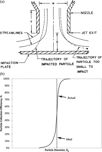
The cut-size of an impactor stage is the aerodynamic diameter that is collected at 50% efficiency and is a function of the nozzle diameter, the number of nozzles, the flow rate through the nozzles, and to a lesser extent the physical design of the nozzle/ impaction plate stage (Marple Citation1970).
For the purpose of determining the particle size distribution of an aerosol, a cascade impactor is used. In a cascade impactor the aerosol is passed through a series of impactor stages, with each stage in the series collecting smaller particles than the stage before it (Marple and Rubow Citation1986).
In the study of impactors, it is common practice to express the equations governing the flow field and particle trajectories within impactors in dimensionless form (Radar and Marple Citation1985). The Navier-Stokes equations are used to define the flow field, and when put in dimensionless form, the Reynolds Number, Re, becomes a parameter that defines the flow field. Likewise, the force equation F = ma defines the particle trajectory, and when put in dimensionless form, the Stokes number, Stk, becomes a parameter that defines the particle trajectory. These two parameters are:
and
where ρg = air density, W = nozzle diameter, U = air velocity, Q = total flow rate through stage, Cc = slip correction, n = number of nozzles on stage.
In practice, the number of nozzles can be adjusted to obtain the desired nozzle Re value. Thus, impactor stages will often contain multiple nozzles, in some cases reaching values of several thousand. The distance between adjacent nozzles is generally termed the Nozzle Spacing Ratio, or NSR, and is defined as:
Note that with this definition, a nozzle spacing ratio of unity results in nozzles with adjacent edges physically touching each other.
Generally speaking, using single nozzle theory to determine the flow and particle collection characteristics of multinozzle impactor stages is reasonable, assuming that the nozzles are spaced “far enough” apart to neglect the nonidealities associated with the jet interactions. While studies have been done analyzing a cluster of nozzles and the effect of nozzle spacing in the macro scale (Fang et al. Citation1991), there has been little fundamental research on the topic of jet interactions between individual nozzles.
Analysis of deposits from multiple round nozzle impactor stages (Fang et al. Citation1991), and to a lesser extent even from single round nozzle stages (Sethi and John Citation1993), shows particle collection in areas other than directly beneath the nozzles where the air jets impinge directly upon the impaction plate. In some cases there are secondary deposits that manifest themselves as “halos” around the primary deposits (both single and multiple nozzle stages), or straight lines directly between adjacent nozzles, both on the impaction plate and on the backside of the nozzle plate (multiple nozzle stages only). Current belief is that the quantity of particles in the deposit on the backside of the nozzle plate is negligible compared to the quantity of particles collected on the impaction plate (Rocklage Citation2007). Thus, it is common practice to ignore the deposit on the backside of the nozzle plate, while considering the primary and secondary deposits on the impaction plate as the deposit for that stage. Since particles collected in places other than the primary deposit are particles that initially escaped collection at the primary location, the particle collection efficiency curves can be expected to deviate from the curves generated from data of the primary deposits alone.
The objective of this article is to determine under what conditions of jet Reynolds number and spacing distance between the nozzle pairs will cause these secondary deposits to occur and to quantify the fraction of the collected particles in the various secondary deposition locations. A two-step approach was used to study the nature of these deposits. The first step was to initiate an experimental test program to determine what secondary deposits will form, and the relative quantity of particles collected in these deposits. The second step was to use CFD analysis to determine the mechanisms that cause particle deposition at these various locations.
It should be noted that this study considers only the nature of the deposits when two nozzles are considered. When more than two nozzles are used in a single impactor stage there can be deposit distortions due to the cross-flow of spent air from the nozzles near the center of the nozzle cluster past the impaction zone of the nozzles near the circumference of the nozzle cluster. This may result in deposits that are not circular, often being kidney-shaped or, in severe cases, resulting in no deposit at all (Fang et al. Citation1991).
METHODS
Experimental Study
Eight different test conditions were evaluated with a combination of Reynolds numbers at various nozzle spacing ratios. To determine the effect of Reynolds number on the deposition pattern, tests were run for four values of Re spanning the recommended operating range (Marple and Willeke Citation1976). The Reynolds numbers tested included 500, 1000, 1875, and 3000. To determine the effect of nozzle spacing ratio, values of 2.5 and 4.0 were selected, which covers the range normally found in commercial impactors. The impactor was the “flat plate”-type with nozzles consisting of drilled and reamed holes with 30° chamfered upstream edges. The particle size range tested was all supermicron-sized particles, ranging from 1.3 μm to 6.3 μm. Settling velocities over the particle range varied from 3.5E-05 m/s to 1.5E-03 m/s.
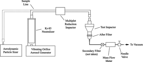
The procedure for experimentally determining the fraction of particles in any deposition location was the same as for determining an impactor collection efficiency curve (Marple et al. Citation2003). The test aerosol was made up of monodisperse oleic acid particles tagged with a fluorescent uranine tracer dye generated by a TSI Model 3450 Vibrating Orifice Aerosol Generator (VOAG). The particles were diluted with clean, dry air, and then charge neutralized using a Kr-85 source. Any particle multiplets were eliminated from the air stream using a Multiplet Reduction Impactor (MRI) before being introduced to the test impactor (Siegford et al. Citation1994). The test impactor was operated at a specific flow rate that was controlled by a needle valve and a mass flow meter. The particle size was verified prior to and after each test using an aerodynamic particle sizer (APS). is a schematic of the experimental test setup.
After a specified test duration, which was dependent on the challenge aerosol particle diameter and concentration, deposits from the impaction plate, nozzle backside surface, and after-filter of the test impactor were collected. Each of the separate deposit locations were collected separately and the samples were analyzed fluorometrically to determine the relative particle deposition by location. This final step was difficult and required significant attention to detail, especially when the deposits were close together.
Computational Study
The experimental investigation into the secondary deposits provided substantial information on the location of the deposits as well as the relative quantities of particles in each deposit, but little, if any, information on the mechanisms of the particle deposition at these locations. To answer this question, a fully verified computational model was employed. The program (CFX 10.0 Citation2007) was a commercially available three-dimensional finite volume Computational Fluid Dynamics (CFD) software package from Ansys Inc. An initial study performed on a single nozzle model verified that the results compared well to theory and literature (Rocklage Citation2007).
The Navier-Stokes equations were first solved in order to obtain information on the flow field. The particle trajectories through the flow field were then solved using an Eulerian-Lagrangian method. The flow field through the domain was modeled with air as the continuous medium, and solid, homogeneous particles as the dispersed phase. Due to the assumption of laminar flow in the model, the CFD analysis was limited to Re of 500 and 1000.
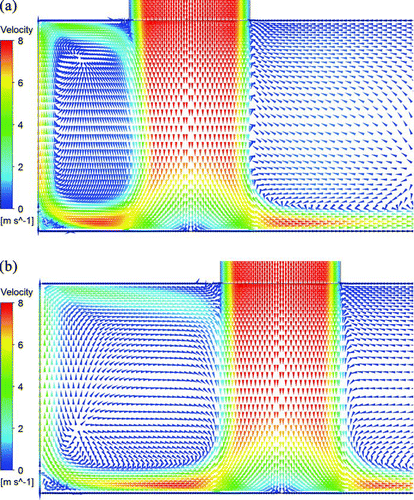
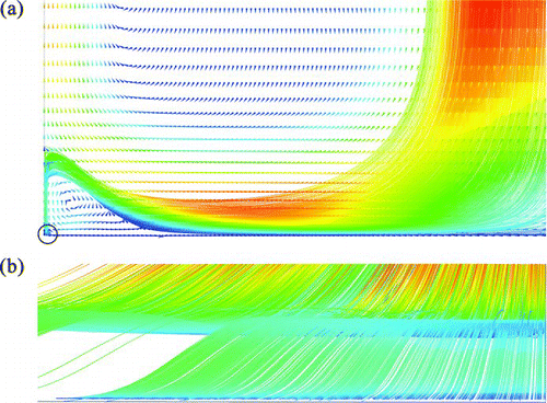
The flow field can be illustrated in several forms, but it was found that velocity vector plots were best in illustrating deposition mechanisms. Such plots are shown in for Re of 1000 and NSR of 2.5 and 4.0, respectively. Tracing out particle trajectories in these flow fields will indicate if particles of specific sizes are predicted to be deposited at any secondary deposit locations. It should be noted that the CFD program does not automatically take into account the particle radius when determining whether a particle has been collected. However, this was added to the program manually to make the solution more realistic.
EXPERIMENTAL RESULTS
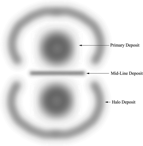
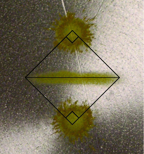
Depending on the particle diameter, samples were found to be collected at one or more of three distinct locations on the impaction plate, as shown in . These include the deposit directly under the nozzle (primary deposit), a “halo” deposit around, but displaced from, the primary deposit, and a straight midline deposit between, and equal distance from, the two primary deposits. A fourth deposit area, which was noted and documented in this study, was on the backside of the nozzle plate. Although this deposit was normally a small percentage of the total, it is included in this study for completeness.
FIG. 5 Deposition as a function of Re for (a) midline, (b) halo, (c) nozzle plate, and (d) primary depositions (NSR = 2.5). (Color figure available online.)
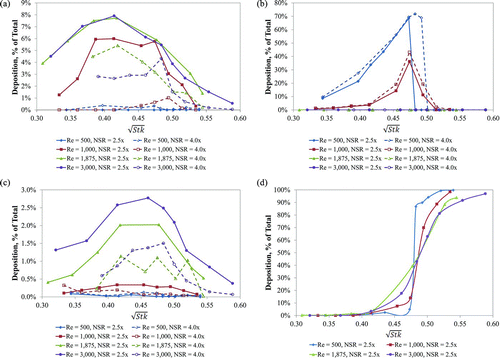
The results for the eight cases tested are presented graphically in for NSR of 2.5 and 4.0. The percentages listed in this figure are the percentages of the particles passing through the nozzle that are collected at that location. From these data, it is possible to determine the influence of the dimensionless particle size (![]() ), dimensionless flow rate (Re), and nozzle spacing ratio (NSR) on the relative quantities of particles in the primary, midline, halo, and nozzle backside deposits. For example, shows the influence of Re as a function of
), dimensionless flow rate (Re), and nozzle spacing ratio (NSR) on the relative quantities of particles in the primary, midline, halo, and nozzle backside deposits. For example, shows the influence of Re as a function of ![]() on the deposition of particles at the various locations. From this figure, several conclusions can be drawn:
on the deposition of particles at the various locations. From this figure, several conclusions can be drawn:
| 1. |
shows that midline deposits only form at larger values of Re (Re ≥ 1000) and, in general, form at lower values of | ||||
| 2. |
shows that the halo deposit is only present at lower values of Re (Re ≤ 1000). This figure also shows that the halo deposit forms at lower | ||||
| 3. | shows that the nozzle plate deposit is always less than 3% of the total. This deposit is nearly non-existent at lower Re flows. | ||||
| 4. | shows the primary deposit only as a function of Re. It can be seen that when the primary deposit is taken by itself that the collection efficiency curve is actually steepest for lower Re flows. | ||||
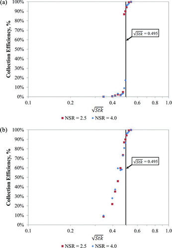
The data also reveal that the collection efficiency curve is very sharp when only the primary deposit is considered as shown in . If the halo deposit is also considered, which is normally the case if an impactor stage is calibrated; the cut is not as sharp, as shown in . As discussed previously, this also indicates that the halo deposit starts to form at lower ![]() than the primary deposit. The same conclusion can be drawn when the midline deposit is considered for the larger Re cases, where a midline deposit is present.
than the primary deposit. The same conclusion can be drawn when the midline deposit is considered for the larger Re cases, where a midline deposit is present.
COMPUTATIONAL RESULTS
Midline Deposit
show end and side views, respectively, of particle trajectories at the midline deposit location for a particle of ![]() and Re = 1000. The round circles on indicate particle impaction at the midline deposit location and note that many particle trajectories terminate (impact) here. The side view of these trajectories in shows that these particle impaction points are spread out over some distance, forming a linear deposit.
and Re = 1000. The round circles on indicate particle impaction at the midline deposit location and note that many particle trajectories terminate (impact) here. The side view of these trajectories in shows that these particle impaction points are spread out over some distance, forming a linear deposit.
FIG. 7 CFD particle trajectories at midline deposit location for NSR = 2.5, Re = 1000 and ![]()
The length of this linear deposit appears to be predictable, as shown in . In this figure, an actual deposit is shown with the midline deposit positioned midway between the two primary deposits. The two ends of the midline deposit terminate at a point 45° from a line joining the two nozzles, with the ends of the midline deposit and the two nozzles forming a square. Thus, the midline deposit length will be equal to the distance between the nozzle centerlines. This feature of the midline deposit was noted to be independent of Re in this study.
Nozzle Plate Deposit
Deposition on the nozzle plate is not as well defined as the midline deposit. shows the particle trajectories for the same case as and, again, the circles represent particles that have been captured by the backside of the nozzle plate.
Halo Deposit
In the initial modeling performed for the multinozzle impactor, gravity was not included in the model and the results showed no signs of halo deposits. Subsequently, when gravity was included in the model, the halo deposition pattern became apparent. Once the particles passed a certain distance downstream from the nozzle, the flow velocity would decrease and particles would be captured by sedimentation. The sedimentation pattern agrees well with the phenomena seen in the experimental testing, as shown in . This figure shows the halo deposition pattern, both numerically and experimentally, under similar conditions.
FIG. 9 CFD particle trajectory at nozzle plate deposit location for NSR = 4.0, Re = 500 and particle ![]()
FIG. 10 Deposition pattern showing halo deposit for Re = 500, NSR = 2.5 from (a) CFD analysis, ![]()
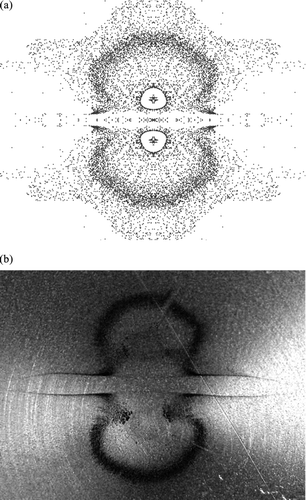
Note that in the area midway between the two nozzles is devoid of particle deposition. This apparently due to a zone of higher velocity in this region as air escapes the impaction region, which prevents particles from being deposited.
If sedimentation is dependent on the nozzle Reynolds number and the diameter of the particle, it should be assumed that as the particle size increases, the particle would tend to drift more quickly to the surface. This was observed in the experimental results, where the location of the halo would move inward as the particle diameter was increased. Also, as the nozzle Reynolds number is increased, the velocity of the flow downstream of the nozzle is increased. This causes fewer particles to be captured in the halo region, and again verifies the experimental results that showed the halo deposition decreasing as the Reynolds number increased.
Discussion of Results
The location and relative magnitude of particle deposition has been determined for double nozzle inertial impactors. The deposition locations include the three impaction plate deposits (primary, midline, and halo) shown in , as well as the nozzle plate deposit. While shows the general location and shape of the impaction plate deposits for the paired nozzle configuration, the deposits tend to vary, sometimes dramatically, between different Reynolds numbers, nozzle spacing ratios, and particle diameters.
Primary Deposit
The primary deposit is directly below the nozzle and is generally slightly larger than the nozzle diameter. If only the primary deposit is considered, the particle collection efficiency curve is generally very sharp, and becomes less sharp if the secondary deposits are considered. A feature observed in the formation of the primary deposit is that at the smallest value of ![]() where particles just start to be deposited, the deposit appears as an annulus. Since the efficiency curve is very sharp, this annular deposit fills in rapidly for particles of slightly larger values of
where particles just start to be deposited, the deposit appears as an annulus. Since the efficiency curve is very sharp, this annular deposit fills in rapidly for particles of slightly larger values of ![]() . It should be noted that only two nozzles were considered in this study. If larger numbers of nozzles are used, the circular primary deposit can become distorted due to the cross-flow conditions that may be present at the impaction plate (Fang et al. Citation1991).
. It should be noted that only two nozzles were considered in this study. If larger numbers of nozzles are used, the circular primary deposit can become distorted due to the cross-flow conditions that may be present at the impaction plate (Fang et al. Citation1991).
Midline Deposit
The CFD analysis showed a recirculation region on the impaction plate mid-way between adjacent nozzles. This recirculation forms a stagnation point that facilitates the deposition of particles by impaction and interception that are caught up in the recirculation. The midline deposit appears as a well-defined straight line that ends at about a 45° angle from a line between the nozzles.
As indicated in , midline deposits appear at ![]() values smaller than those of the primary deposits and peaks at
values smaller than those of the primary deposits and peaks at ![]() values slightly smaller than where the primary deposits start to form. As expected, midline deposition disappears when nearly 100% of the particles are collected in the primary deposit. This figure also shows that the value of the Reynolds number has a substantial effect on the extent of particle midline deposition, with negligible deposition (<1%) at Re = 500 for NSR = 2.5 or Re = 500 and 1000 for NSR = 4.0. Midline deposition was present for all other cases, reaching maximum values of about 8% and 5% of the total for 2.5 and 4.0 nozzle spacing ratios, respectively. In addition, the nozzle spacing ratio has a substantial effect on the midline deposition, in that deposition is increased as the nozzle spacing is reduced. This is due to increased interaction between the nozzles which results in a higher recirculation velocity and increased particle impaction and interception.
values slightly smaller than where the primary deposits start to form. As expected, midline deposition disappears when nearly 100% of the particles are collected in the primary deposit. This figure also shows that the value of the Reynolds number has a substantial effect on the extent of particle midline deposition, with negligible deposition (<1%) at Re = 500 for NSR = 2.5 or Re = 500 and 1000 for NSR = 4.0. Midline deposition was present for all other cases, reaching maximum values of about 8% and 5% of the total for 2.5 and 4.0 nozzle spacing ratios, respectively. In addition, the nozzle spacing ratio has a substantial effect on the midline deposition, in that deposition is increased as the nozzle spacing is reduced. This is due to increased interaction between the nozzles which results in a higher recirculation velocity and increased particle impaction and interception.
Halo Deposit
While the appearance of halo deposits is not caused by the presence of multiple nozzles, it still has an effect on the shape of the deposition curve. For single nozzle impactors, the halo deposit occurs at a specific radial distance downstream from the nozzle depending on the particle's ![]() value. This results in a ring-shaped deposit surrounding the primary deposit. As shown in , for two nozzles the deposit generally takes the form of two horseshoe-shaped curves around the primary deposits. The open sections of the two halos are due to locally higher flow velocities in the jet interaction region.
value. This results in a ring-shaped deposit surrounding the primary deposit. As shown in , for two nozzles the deposit generally takes the form of two horseshoe-shaped curves around the primary deposits. The open sections of the two halos are due to locally higher flow velocities in the jet interaction region.
Deposition in the halo region appears to be due to particle sedimentation. As the air flow moves radially outward from the nozzle centerline, the local flow velocity decreases due to conservation of mass and particles begin to settle out of the flow. This phenomenon causes the halo deposits to form. In general, the computer models show that particles that initially escape collection in the primary deposit are already very close to the impaction plate, thus minimal settling is required to capture these particles. It was observed that larger particles will form halo deposits closer to the primary deposit than smaller particles due to the increased effect of gravity on the larger particles. The halo deposit is most pronounced at lower Reynolds numbers, and decreases in percentage of total deposition as the Reynolds number increases, disappearing completely above a Reynolds number of 1000. It should be noted that these conclusions do not necessarily apply to submicron size particles as diffusion was not taken into account in the models. The halo deposit is most likely to be affected since the phenomenon is dependent on particle sedimentation.
CONCLUSIONS
The objective of this work was to experimentally determine the location of secondary impaction deposits and to determine the magnitude of the deposition as a function of particle diameter, Reynolds number and nozzle spacing. Once this was completed, the collection mechanism for these deposits was determined using computational methods. It was determined that the midline and nozzle deposits are caused by a combination of impaction and interception, while the halo deposits are formed by particle sedimentation. It was found that nozzle plate deposits can be anywhere from zero to about 3% of the total particles, the midline deposits can be up to 8% of the total particles, while under certain conditions the halo deposits can contain nearly all of the impaction plate deposit. From these data it should be noted that while midline and nozzle deposition may be tolerated, the halo deposits should be avoided, if possible, when designing or operating a round nozzle impactor. The simplest method of accomplishing this is to operate at a higher Reynolds number range (Re > 1000 for this study) where the halo deposits were negligible. This is further evidenced by considering the particle collection efficiency curve for the case of Re = 500, as shown in . When only the primary deposit, or the primary and midline deposits combined, is considered, the particle collection efficiency curve is the steepest of all cases tested. However, once the effect of the halo deposit is included, the collection efficiency curve becomes dramatically shallower.
REFERENCES
- ANSYS CFX . 2007 . Release 10.0 , ANSYS, Inc .
- Fang , C. P. , Marple , V. A. and Rubow , K. L. 1991 . Influence of Cross-flow on Particle Collection Characteristics of Multi-Nozzle Impactors . J. Aerosol Sc. , 22 : 403 – 415 .
- Marple , V. A. 1970 . A Fundamental Study of Inertial Impactors , Minneapolis, MN : University of Minnesota . Ph.D. Thesis
- Marple , V. A. , Olson , B. A. , Santhanakrishnan , K. and Mitchell , J. P. 2003 . Next Generation Pharmaceutical Impactor (A New Impactor for Pharmaceutical Inhaler Testing)—Part II: Archival Calibration . J. Aerosol Med. , 16 ( 3 ) : 301 – 324 .
- Marple , V. A., and Rubow , K. L. 1986 . “ Theory and Design Guidelines ” . In Cascade Impactors: Sampling & Data Analysis , Edited by: Lodge , J. P. and Chan , T. L. 79 – 101 . Akron, OH : American Industrial Hygiene Association .
- Marple , V. A. and Willeke , K. 1976 . Impactor Design . Atmo. Environ. , 10 : 891 – 896 .
- Rader , D. J. and Marple , V. A. 1985 . Effect of UltraStokesian Drag and Particle Interception on Impactor Characteristics . Aerosol Sci. Technol. , 4 : 141 – 156 .
- Rocklage , J. M. 2007 . A Fundamental Study of Jet Interactions in Multi-Nozzle Inertial Impactors , Minneapolis, MN : University of Minnesota . M.S. Thesis
- Siegford , K. L. , Marple , V. A. and Rubow , K. L. 1994 . A Multiplet Reduction Impactor for the Vibrating Orifice Aerosol Generator . J. Aerosol Sci. , 25 ( S1 ) : 113 – 114 .
- Sethi , V. and John , W. 1993 . Particle Impaction Patterns from a Circular Jet . Aerosol Sci. Technol. , 18 : 1 – 10 .
