
Abstract
Fernández-Díaz and Domat's preceeding Letter to the Editor argued that the geometry of the discharge electrode of the charger of our previous article entitled “Modeling and Validation of Nanoparticle Charging Efficiency of a Single-Wire Corona Unipolar Charger” was a needle but not a wire. Therefore, the boundary condition for the ionic charge density at the discharge wire surface used in the simulation was suspected to be not completely correct. In the present work, the exact shape of the tip of the discharge electrode was examined and found as a hyperbolic point. The experimental onset voltage was further compared with the theoretical onset values calculated by either wire-in-tube or point-to-plane assumption. Results show that the theory of needle-type discharge electrode is also not appropriate either for the boundary condition at the tip because of higher calculated onset voltages than the experimental data.
Copyright 2014 American Association for Aerosol Research
In Chien et al. (Citation2011), a detailed two-dimensional (2D) numerical model was developed to predict the flow, electric potential, ion concentration, charged particle concentration fields, charged particle loss, and charging efficiency in a single-wire corona unipolar charger. The numerical model is able to predict the experimental nanoparticle charging efficiency very well for particles smaller than 20 nm in diameter. However, Fernández-Díaz and Domat (Citation2014) argued in their Comment that the geometry of the discharge electrode of the charger was a needle but not a wire, and hence the boundary condition for the ionic charge density at the discharge wire surface used in the simulation was not completely correct. They proposed a methodology to replace Equation (9) in Chien et al. (Citation2011) for improving the simulated results.
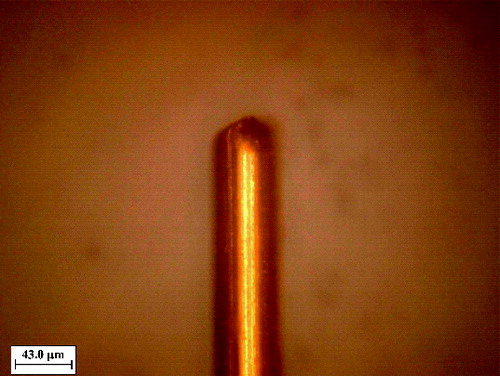
The exact shape of the tip of the discharge electrode was examined by an electron microscope (ESPA SYSTEMS Co., Ltd., Hsin Chu, Taiwan) and is shown in . The shape of the tip is seen as a hyperbolic point corresponding to the case A in in the Comment by Fernández-Díaz and Domat (Citation2014). The equivalent radius of curvature of the point is equal to 23.7–24 μm, which is slightly smaller than the radius of wire, 25 μm. The blackish wire surface was caused by oxidation.
FIG. 1. Micrograph of the tip of discharge electrode of the charge of Chien et al. (Citation2011).
For the irregular internal geometry of the charging chamber, no simple mathematical models were available to describe the electrical field between the tip of the discharge and grounding electrodes until the numerical work conducted by Chien et al. (Citation2011). For the breakdown voltage and breakdown electric field in point-to-plane corona discharge, the breakdown voltage, V0 (V), is expressed as (Adamiak et al. Citation2005; Le et al. Citation2013)
[1] where a is the tip radius of discharge electrode (m), d is the point-to-plane spacing (m), and
is the breakdown electric field (V/m) which can be calculated as
[2] where a is in cm, and
is the relative density of the air. The ion current of a single electrode can be calculated as follows (Adamiak and Atten Citation2004; Le et al. Citation2013):
[3] where I is the corona current (A),
is the empirical coefficient, which is 1.58 suggested by Adamiak and Atten (Citation2004),
is the permittivity of air (C2/N-m2), Zi is the ion mobility (m2/s·V), and
is the applied voltage (V).
The breakdown voltage for the wire-in-tube precipitator (ESP) can be calculated as (Tsai et al. Citation2008)
[4] where rw is the radius of the discharge wire (m),
is the radius of the tube (m), and the breakdown electric field is
[5] where
is the diameter of the discharge wire (m). The corona voltage is given by
[6] where is defined as
[7]
In the charging chamber, the distance from the tip to the inlet and wall are 0.02 m and 0.015 m, respectively, as shown in Figure 3 in Chien et al. (Citation2011). For the point-to-plane corona discharge, the breakdown voltage was calculated to be 2.98 kV (d = 0.02 m) and 2.87 kV (d = 0.015 m) at a = 24 μm with the corresponding breakdown electric field of V/m, which is close to that calculated by EquationEquation (5)
[5] in the Comment. For the wire-in-tube case, the breakdown voltage was calculated to be 3.35 kV with the corresponding breakdown electric field of
V/m, which is also close to that calculated by EquationEquation (4)
[4] in the Comment. As shown in , the experimental onset voltage is much lower than the theoretical onset values calculated by either wire-in-tube or point-to-plane assumption.
FIG. 2. Comparison of the applied and theoretical onset voltages.
Besides, the applied voltage of +1.6 to + 2.4 kV (corona current: 0.001 to 1.817 μA) and −1.6 to −2.4 kV (corona current: −0.004 to −2.087 μA) in the charging experiment of Chien et al. (Citation2011) for positive corona and negative corona, respectively, is much lower than the above calculated onset voltages. The corona current at the onset voltage is zero, which is not the operating condition of the charger. Instead, the maximum charging efficiency occurs at a certain voltage within the applied voltage range of ±1.6 to ±2.4 kV, which is even lower than the calculated onset values.
We agree with Fernández-Díaz and Domat (Citation2014) that Equation (9) in Chien et al. (Citation2011) is only valid for a wire but not for a tip. However, the theory of needle-type discharge electrode is also not appropriate either for the boundary condition at the tip because of higher calculated onset voltages than the experimental data. Besides, particle charging can only occur at a voltage higher than the onset voltage and the numerical study for particle charging was based on the corona current obtained experimentally in Chien et al. (Citation2011). The predicted extrinsic charging efficiencies were shown to be in good agreement with the experimental data with a deviation of <7%, which cannot be improved further by the method proposed by Fernández-Díaz and Domat (Citation2014).
REFERENCES
- Adamiak, K., Atrazhev, V., and Atten, P. (2005). Corona Discharge in the Hyperbolic Point-Plane Configuration: Direct Ionization Criterion versus Approximate Formulations. IEEE Trans. Dielectr. Electr. Insul., 12:1025–1034.
- Adamiak, K., and Atten, P. (2004). Simulation of Corona Discharge in Point-Plane Configuration. J. Electrostat., 61:85–98.
- Chien, C. L., Tsai, C. J., Chen, H. L., Lin, G. Y., and Wu, J. S. (2011). Modeling and Validation of Nanoparticle Charging Efficiency of a Single-Wire Corona Unipolar Charger. Aerosol Sci. Technol., 45:1468–1479.
- Fernández-Díaz, J. M., and Domat, M. (2014). Comment on “Modeling and Validation of Nanoparticle Charging Efficiency of a Single-Wire Corona Unipolar Charger.” Aerosol Sci. Technol. 48(12):i–iii.
- Le, T. C., Lin, G. Y., and Tsai, C. J. (2013). The Predictive Method for the Submicron and Nano-Sized Particle Collection Efficiency of Multipoint-to-Plane Electrostatic Precipitators. Aerosol Air Qual. Res., 13:1404–1410.
- Tsai, C. J., Chen, S. C., Chen, H. L., Chein, H. M., Wu, C. H., and Chen, T. M. (2008). Study of a Nanoparticle Charger Containing Multiple Discharging Wires in a Tube. Sep. Sci. Technol., 43:3476–3493.