Abstract
Particle deposition and resuspension during turbulent flow were investigated using a rectangular channel with glass side walls. Micrometer-sized alumina particles were used in the experiments. Particle behavior in the rectangular channel was observed through a high-speed microscope camera with a resolution of 0.3 μm and a speed of 87,600 fps, and particle deposition and resuspension fluxes were quantified using digital image analysis. The experimental results showed that particle resuspension was caused by the collision of airborne particles with those deposited on the surface. The resuspension flux was found to be correlated with the deposition flux. Furthermore, the average residence time between particle deposition and resuspension was several tens of milliseconds, which was very short but much longer than the contact time at the collision. Additionally, the residence time decreased as the particle diameter increased.
Copyright 2015 American Association for Aerosol Research
INTRODUCTION
Particle deposition in turbulent flow has been attracting increased attention due to its relevance in a large number of processes such as pneumatic conveying, dust collection, particle sampling, and the nucleation and growth of particles; consequently, many experimental, theoretical, and computational studies have been reported over the past few decades (Wood Citation1981; Papavergos and Hedley Citation1984; Tian and Ahmadi Citation2007).
When particles are deposited on a surface, adhesive forces act on them; however, if aerodynamic and other external forces acting on these particles are larger than the adhesive forces, the particles are resuspended into the surrounding fluid. Particle resuspension is considered different from rebound and saltation, since the former occurs after the particles maintain a stationary state for a given period, while rebound and saltation occur in a state of continuous motion.
Particle deposition and resuspension depend on existing conditions. If particles are very small, resuspension does not occur even in turbulent flow. When small particles are deeply immersed within a boundary layer, the aerodynamic forces acting on the particles are too weak to remove them. The deposited particles then accumulate on the surface, forming particle layers (Matsusaka et al. Citation1993, Citation1998, Citation2001b). However, the agglomerated particles on top of the particle deposition layers experience greater aerodynamic forces and can be readily resuspended (Matsusaka and Masuda Citation1996). Particle resuspension, therefore, depends on particle diameter and the state of the deposited particles, which must be in either monolayer deposits (deposited sparsely on the surface) or multilayer deposits with a packed structure (Boor et al. Citation2013a,Citationb).
Particle resuspension from a monolayer has been studied by a number of researchers. Cleaver and Yates Citation(1973) developed a force balance model for particle resuspension in turbulent flow and derived an equation for calculating the resuspension rate, while considering the fluctuation of the force based on turbulent burst. Braaten et al. Citation(1990) implemented a Monte Carlo simulation using the force balance concept. The force balance models have been extended to moment balance models, which include the effect of rotation (Wang Citation1990; Tsai et al. Citation1991; Matsusaka et al. Citation1996, Citation1997; Ziskind et al. Citation1997; Toscano and Ahmadi Citation2003). In addition, other models have been presented by Reeks et al. Citation(1988), Wen and Kasper Citation(1989), and Reeks and Hall Citation(2001) to explain the time dependence of the particle resuspension. For the last decade, more detailed experimental and theoretical studies have been carried out to clarify the mechanism of detachment, motion, and trajectory, and effects of particle size, surface roughness, and material (Ibrahim et al. Citation2003; Jiang et al. Citation2006, Citation2008; Ziskind Citation2006; Guingo and Minier Citation2008; Fu et al. Citation2013; Goldasteh et al. Citation2013; Kassab et al. Citation2013; Barth et al. Citation2014). On the other hand, resuspension of agglomerated particles from a powder layer was studied by Matsusaka and Masuda Citation(1996). They used the moment balance model proposed by Kousaka et al. Citation(1980) and presented a new model to explain time dependence in steady- and unsteady-state flows, taking into account the adhesive strength distribution of particles, surface renewal of the powder layer, and time delay of the resuspension.
For continuous processes, particle resuspension can occur simultaneously with particle deposition. John et al. Citation(1991) pointed out that the collision of airborne particles with deposited particles causes resuspension of the deposited particles. The formation of deposition layers with these simultaneous processes was also studied (Matsusaka et al. Citation1998, Citation2001a,Citationb). Resuspension of agglomerated particles from deposition layers was explained by a model that considers both the impact of airborne particle and the aerodynamic force (Adhiwidjaja et al. Citation2000; Theerachaisupakij et al. Citation2002, Citation2003). This concept has been used for other applications such as surface cleaning using a dry ice jet (Toscano and Ahmadi Citation2003; Liu et al. Citation2011). The moment balance model showed that the rolling removal of deposited particles is more significant than sliding removal based on force balance. However, when the deposited particles are not spherical, the sliding model may be more important (Banerjee and Campbell Citation2005).
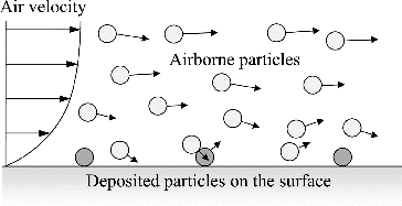
Single fine particles are generally difficult to remove from a surface. To allow for their removal, a high-velocity flow is usually needed. However, when airborne particles collide with the deposited particles, the latter can be resuspended even if the flow velocity is not very high (John et al. Citation1991). The concept of particle-induced resuspension in dilute-phase pneumatic conveying is shown in . To confirm and elucidate resuspension, microscopic observation is required; however, few studies have undertaken this.
In the present study, simultaneous particle deposition and resuspension was observed in turbulent flow using a high-speed microscope camera. Furthermore, the correlation between particle deposition and resuspension was quantitatively analyzed through digital image processing.
EXPERIMENTAL SETUP AND PROCEDURE
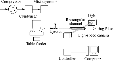
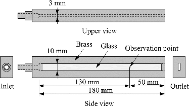
shows a schematic of the experimental setup for the pneumatic conveying of fine particles. Particle deposition and resuspension were observed using this setup. Air was supplied from a compressor and dried through a condenser, and its relative humidity was maintained at 10%. The particles were continuously fed by a table feeder (MFOV-1, Sankyo Pio-Tech. Co., Ltd., Japan). To maintain a constant feed rate, the particles were directly sucked from the particle layer, which was formed on a rotating table, into a narrow tube (Masuda et al. Citation1994; Matsusaka et al. Citation2008) and dispersed into the airflow through an ejector (VRL 50–080108, Nihon Pisco Co., Ltd., Japan). As shown in , the test section was a rectangular channel 10 mm high, 3 mm wide, and 180 mm long with glass side walls whose surface roughness, Ra, was less than 10 nm. The channel was irradiated from the rear for clear observation of the outlines of the particles as shadow pictures. Particle deposition on the front glass and resuspension were both observed though a high-speed camera (Fastcam-Max, Photron Ltd., Japan) with a zoom lens (CX-2525CS, Hirox Co., Ltd., Japan). Images were captured at 87,600 fps with a resolution of 0.3 μm. Particle deposition and resuspension were automatically determined by digital image processing.
For the analysis, the Dipp-Macro program (DITECT Corporation, Japan) was modified. When the position of a particle did not change in at least three temporally continuous image frames (i.e., 22.8 μs), the particle was considered to be deposited on the surface. For example, if particle displacement is 1 μm for a period of 22.8 μs, the particle velocity is 0.04 m s−1. If fine particles approach the surface at such low velocities, they will be deposited without rebound. A preliminary experiment indeed showed that after the position of fine particles did not change within the minimum period of 11.4 μs, the particles did not move again. Particle deposition and resuspension fluxes, as well as the trajectories of particle deposition and resuspension, were obtained by image analysis.
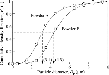
In this experiment, two types of alumina powders were used. shows their number-based particle size distributions. The median diameters of the sample Powders A and B were 3.1 and 4.3 µm, respectively. Their physical properties are summarized in . These particles were dried at 130°C for 12 h and cooled to room temperature in a desiccator. All the experiments were conducted at room conditions (temperature: 18–25°C; relative humidity: 35–50%).
TABLE 1 Properties of the two types of alumina powders
RESULTS AND DISCUSSION
Basic Features of Simultaneous Particle Deposition and Resuspension
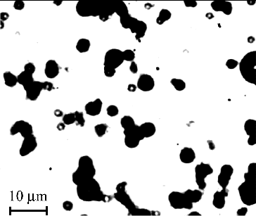
Experiments were conducted to study the process of simultaneous particle deposition and resuspension in a rectangular channel. The behavior of particles on the glass side wall was observed though a high-speed microscope camera. An image of particles, which can be clearly observed at the micrometer size with this system, is shown in . Particle deposition on the surface increased with time, but the deposition amount approached an equilibrium value, which was determined by the balance between the particle deposition and resuspension rates. The particle deposition rate and the time taken to reach equilibrium depended on experimental conditions such as air velocity, Reynolds number, particle diameter, particle density, and particle concentration. At low air velocities, multilayer deposits formed on the surface, but they disappeared at higher air velocities. The size of particles adhering to the surface also decreased with increasing air velocity. These behaviors were found to be consistent with those reported in previous papers (Adhiwidjaja et al. Citation2000; Matsusaka et al. Citation2001b).
Particle deposition can be characterized by the dimensionless relaxation time of particles, τ+, and dimensionless deposition velocity, vd+ (Papavergos and Hedley Citation1984). τ+ is defined as[1] in which relaxation time, τ, is given by
[2] where u* is the friction velocity, ν is the kinematic viscosity, ρp is the particle density, Dp is the particle diameter, CC is the Cunningham slip correction factor, and μ is the viscosity. On the other hand, vd+ is defined as
[3] in which deposition velocity, vd, is given by
[4] where Jd is the deposition flux, and C is the number concentration of particles in airflow.
The dimensionless relaxation time, τ+, depends on experimental conditions such as average air velocity (u), Reynolds number (Re), particle diameter (Dp), and particle density (ρp). At the conditions of u = 10 m s−1, u* = 0.73 m s−1, Re ≈ 3100, Dp = 3.4 µm, and ρp = 3900 kg m−3, τ+ ≈ 5 can be calculated. Since 0.2 < τ+ < 20, the particle deposition is primarily controlled by particle inertia and turbulent diffusion. The experimentally obtained value of the dimensionless deposition velocity (vd+) at the above conditions was 5 × 10⁻². This value was found to be within the range of 1 × 10⁻³ to 1 × 10⁻¹, which was obtained by many researchers (Papavergos and Hedley Citation1984).
In order to form monolayer deposits found in dilute-phase pneumatic conveying, further particle deposition and resuspension experiments were conducted under the following conditions: u = 10 and 20 m s−1, and C ≈ 1012 m−3. Particle deposition and resuspension fluxes were measured at an equilibrium state. The detailed flow conditions in the channel are summarized in .
TABLE 2 Detailed flow conditions in the channel
Trajectories of Particles
shows the trajectories of three single particles during the deposition and resuspension processes. In the figure, x and y are the horizontal and vertical coordinates, respectively, of the front glass wall of the rectangular channel, and the air flows from left to right. The displacement of a particle as a function of time was obtained from video images recorded at 87,600 fps, and the circles indicate the position of the particles. The area of each circle is equal to the projected area of a particle. The time intervals between the data are 11.4 μs. Open symbols denote the particles moving in the boundary layer of turbulent flow, and closed symbols denote the particles adhering to the surface. In addition, solid lines and dashed lines denote deposition and resuspension processes, respectively. The values in parentheses indicate residence time between particle deposition and resuspension.
FIG. 6 Particles trajectories during the deposition and resuspension processes (Powder B, u = 20 m s−1, interval of open symbols: 11.4 ms, the values of residence time are shown in parentheses).
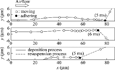
The experimental results showed that the distance moved during each interval decreased with time during the particle deposition process. As expected, the x-component of air velocity in the boundary layer decreased with decreasing distance from the surface. The particle movement in the vertical direction was small compared to that in the airflow direction. This implied that the effect of gravity on the movement of fine particles was small. Each particle deposited on the surface maintained its state for a few milliseconds.
However, the particles did move in significantly different directions than the airflow in the particle resuspension process, and the initial velocity of the resuspended particles was rather large due to the collision of airborne particles with the deposited particles. If the deposited particles were resuspended only by aerodynamic forces, the particles would begin to move in the direction of airflow, and the initial velocity should be rather small, as observed by Jiang et al. Citation(2008).
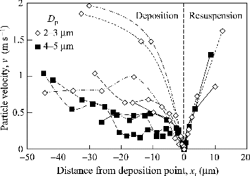
shows the variations in particle velocity during the deposition and resuspension processes. The two-dimensional particle velocities were obtained by the digital processing of video images. The abscissa of this figure is the distance from the surface position at which each particle was deposited. The particle deposition process is in the negative distance range, while the resuspension process is in the positive range. Open and closed symbols in this figure denote smaller (2–3 μm) and larger (4–5 μm) particles, respectively. The particles approached the surface at rather low velocities (v < 2 m s−1). This feature was most prominent for larger particles. If larger particles approach the surface with high velocities, they may rebound due to their greater inertia; however, when approaching slowly, they will be deposited on the surface. Smaller particles, on the other hand, can change their velocity easily according to the local airflow due to lower inertia. In the resuspension process, the particles accelerate rapidly due to the effect of airborne particles colliding with the deposited particles, as mentioned above.
Correlation Between Particle Deposition and Resuspension Fluxes
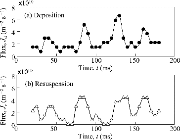
shows the variations of particle deposition and resuspension fluxes (i.e., the transfer rates of particles through a unit area in the deposition and resuspension processes). Although particles were continuously fed into this system, there were minute fluctuations in the feed rate of fine particles due to adhesive forces between particles. As a result, the concentration of the airborne particles in the channel fluctuated. This is a natural phenomenon found in powder handling processes. Because particle deposition flux was proportional to the particle concentration in the airflow, it also fluctuated. Furthermore, the experimental results indicated that the resuspension flux varied according to the deposition flux. As the particle concentration in the airflow increases, the deposition flux will increase, as will the number of collisions between airborne and deposited particles. If particle resuspension occurs due to this collision, the resuspension flux will be synchronized with the deposition flux. To analyze the correlation between these fluxes, focus is given to the periodicity of the fluctuations in each process.
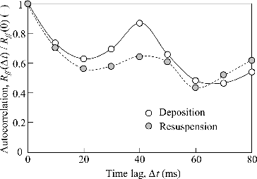
Autocorrelation Rff (j) is defined as[5] where f is an indexed variable (i.e., the data of flux), and N is the upper bound of summation. The autocorrelation, Rff (j), can be converted into Rff (Δt) using the time lag, Δt.
shows the normalized autocorrelations, Rff(Δt)/Rff (0), for the particle deposition and resuspension processes. These autocorrelations had a maximum point at about 40 ms; thus, the particle deposition and resuspension fluxes fluctuated at periods of about 40 ms.
FIG. 9. Normalized autocorrelation functions for the particle deposition and resuspension processes (Powder A, u = 10 m s−1).
Next, the cross-correlation Rfg (j) between the particle deposition and resuspension fluxes was analyzed. Rfg (j) is defined as[6] where g is the other indexed variable.
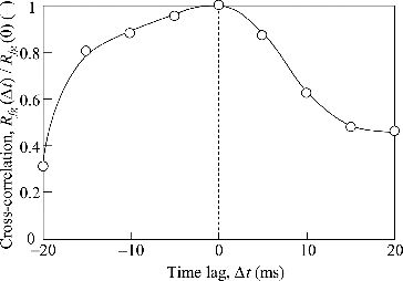
shows the results of the normalized cross-correlation, Rfg (Δt)/Rfg (0), between particle deposition and resuspension as a function of the time lag, Δt. Taking into account the 40 ms interval of fluctuation shown in , the time lag was evaluated in the range of ±20 ms. The normalized cross-correlation was at its maximum at the zero time lag. This indicated that resuspension was synchronized with particle deposition. Particle deposition occurs when airborne particles are transported to the surface. Therefore, the particle deposition flux should be proportional to the particle collision flux. When the airborne particles collide with deposited particles with high-impact forces, the deposited particles will be resuspended. Consequently, the particle resuspension caused by the impact of the airborne particles will be synchronized with the particle deposition.
Residence Time of Particles Adhering to the Surface
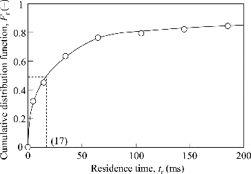
Deposited particles are in a stationary state until they are resuspended. The residence time of particles adhering to the surface (i.e., the period during which the position of particles did not change in temporally continuous image frames) was obtained by digitally processing video images (Dipp-Macro, DITECT Corporation, Japan). shows the cumulative distribution of the residence time for Powder A at u = 10 m s−1. This measurement was conducted at an equilibrium state of simultaneous particle deposition and resuspension. The median value of the distribution was approximately 20 ms, and 80% of particles were resuspended in 100 ms. The residence time between particle deposition and resuspension was very short; however, it was much longer than the contact time at collision.
FIG. 11. Cumulative distribution of the residence time of particles on the surface (Powder A, u = 10 m s−1).
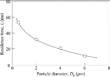
shows the effect of particle diameter on residence time. The residence time decreased as the diameter of the deposited particles increased. This is because the probability of the collision of airborne particles with deposited particles increases with an increase in particle diameter. In addition, larger particles are more easily resuspended due to the larger aerodynamic forces in the boundary layer of turbulent flow. Because the residence time depends on many factors, including air velocity, particle concentration in airflow, and particle impact, further analysis is needed for a more thorough understanding; however, the quantitative analysis in this article can contribute as the basis for this research.
CONCLUSIONS
Particle deposition and resuspension was studied in turbulent channel flow using a high-speed microscope camera. The results obtained can be summarized as follows:
The direction of the particle movement in the deposition process was almost the same as the airflow direction. In the resuspension process, particles moved in significantly different directions than the airflow due to the collision of airborne and deposited particles.
Particle deposition and resuspension fluxes were quantitatively analyzed, finding that the resuspension flux was synchronized with the particle deposition flux.
Deposited particles are in a stationary state until particle resuspension occurs. The median value of the residence time was approximately 20 ms, which was very short but much longer than the contact time at collision. Additionally, the residence time decreased as the particle diameter increased.
NOMENCLATURE
| C | = | particle number concentration (m−3) |
| Cc | = | Cunningham slip correction factor (−) |
| Dp | = | particle diameter, projected area diameter (m) |
| = | number average particle diameter ( = Dp50 exp (0.5 ln2 σg)) (m) | |
| Dp50 | = | number median projected area diameter of particles (m) |
| Fp | = | cumulative particle size distribution (−) |
| Fr | = | cumulative residence time distribution (−) |
| f | = | indexed variable (m−2 s−1) |
| g | = | indexed variable (m−2 s−1) |
| I | = | turbulence intensity ( = urms u−1, = 0.16 Re −1/8) (−) |
| Jd | = | deposition flux (m−2 s−1) |
| Jr | = | resuspension flux (m−2 s−1) |
| N | = | upper bound of summation (−) |
| Rff | = | autocorrelation (m−4 s−2) |
| Rfg | = | cross-correlation (m−4 s−2) |
| t | = | time (s) |
| tr | = | residence time (s) |
| Δt | = | time lag (s) |
| u | = | average air velocity (m s−1) |
| u* | = | friction velocity (=0.2 u Re −1/8) (m s−1) |
| urms | = | root-mean-square of the velocity fluctuations (m s−1) |
| v | = | particle velocity (m s−1) |
| vd | = | deposition velocity (m s−1) |
| vd+ | = | dimensionless deposition velocity (−) |
| x | = | horizontal coordinate (m) |
| xr | = | distance from deposition point (m) |
| y | = | vertical coordinate (m) |
Greek Letters
| μ | = | viscosity (Pa s) |
| ν | = | kinematic viscosity (m2 s−1) |
| ρp | = | particle density (kg m−3) |
| σg | = | geometric standard deviation (−) |
| τ | = | relaxation time of particles (s) |
| τ+ | = | dimensionless relaxation time of particles (−) |
ACKNOWLEDGMENT
The author would like to acknowledge the excellent research assistance provided by Ken-ichi Tominaga.
REFERENCES
- Adhiwidjaja, I., Matsusaka, S., Tanaka, H., and Masuda, H. (2000). Simultaneous Phenomenon of Particle Deposition and Reentrainment: Effects of Surface Roughness on Deposition Layer of Striped Pattern. Aerosol Sci. Technol., 33:323–333.
- Banerjee, S., and Campbell, A. (2005). Principles and Mechanisms of Sub-Micrometer Particle Removal by CO2 Cryogenic Technique. J. Adhesion Sci. Technol., 19:739–751.
- Barth, T., Preuß, J., Müller, G., and Hampel, U. (2014). Single Particle Resuspension Experiments in Turbulent Channel Flows. J. Aerosol Sci., 71:40–51.
- Boor, B. E., Siegel, J. A., and Novoselac, A. (2013a). Monolayer and Multilayer Particle Deposits on Hard Surfaces: Literature Review and Implications for Particle Resuspension in the Indoor Environment. Aerosol Sci. Technol., 47:831–847.
- Boor, B. E., Siegel, J. A., and Novoselac, A. (2013b). Wind Tunnel Study on Aerodynamic Particle Resuspension from Monolayer and Multilayer Deposits on Linoleum Flooring and Galvanized Sheet Metal. Aerosol Sci. Technol., 47:848–857.
- Braaten, D. A., Paw, U. K. T., and Shaw, R. H. (1990). Particle Resuspension in a Turbulent Boundary Layer: Observed and Modeled. J. Aerosol Sci., 21:613–628.
- Cleaver, J. W., and Yates, B. (1973). Mechanism of Detachment of Colloidal Particles from a Flat Substrate in a Turbulent Flow. J. Colloid Interface Sci., 44:464–474.
- Fu, S. C., Chao, C. Y. H., So, R. M. C., and Leung, W. T. (2013). Particle Resuspension in a Wall-Bounded Turbulent Flow. J. Fluid. Eng.-T. ASME, 135:041301.
- Goldasteh, I., Ahmadi, G., and Ferro, A. R. (2013). Monte Carlo Simulation of Micron Size Spherical Particle Removal and Resuspension from Substrate under Fluid Flows. J. Aerosol Sci., 66:62–71.
- Guingo, M., and Minier, J.-P. (2008). A New Model for the Simulation of Particle Resuspension by Turbulent Flows Based on a Stochastic Description of Wall Roughness and Adhesion Forces. J. Aerosol Sci., 39:957–973.
- Ibrahim, A. H., Dunn, P. F., and Brach, R. M. (2003). Microparticle Detachment from Surfaces Exposed to Turbulent Air Flow: Controlled Experiments and Modeling. J. Aerosol Sci., 34:765–782.
- Jiang, Y., Matsusaka, S., Masuda, H., and Qian, Y. (2008). Characterizing the Effect of Substrate Surface Roughness on Particle–Wall Interaction with the Airflow Method. Powder Technol., 186:199–205.
- Jiang, Y., Matsusaka, S., Masuda, H., and Yokoyama, T. (2006). Characterizing the Effect of Surface Morphology on Particle–Wall Interaction by the Airflow Method. Adv. Powder Technol., 17:413–424.
- John, W., Fritter, D. N., and Winklmayr, W. (1991). Resuspension Induced by Impacting Particles. J. Aerosol Sci., 22:723–736.
- Kassab, A. S., Ugaz, V. M., King, M. D., and Hassan, Y. A. (2013). High Resolution Study of Micrometer Particle Detachment on Different Surfaces. Aerosol Sci. Technol., 47:351–360.
- Kousaka, Y., Okuyama, K., and Endo, Y. (1980). Re-entrainment of Small Aggregate Particles from a Plane Surface by Air Stream. J. Chem, Eng. Jpn., 13:143–147.
- Liu, Y. H., Maruyama, H., and Matsusaka, S. (2011). Effect of Particle Impact on Surface Cleaning Using Dry Ice Jet. Aerosol Sci. Technol., 45:1519–1527.
- Masuda, H., Matsusaka, S., and Nagatani, S. (1994). Measurements of Powder Flow Rate in Gas–Solids Pipe Flow Based on the Static Electrification of Particles. Adv. Powder Technol., 5:241–254.
- Matsusaka, S., Adhiwidjaja, I., Nishio, T., and Masuda, H. (1998). Formation of Striped Pattern Deposition Layers by an Aerosol Flow: Analysis of Thickness and Interval of Layers. Adv. Powder Technol., 9:207–218.
- Matsusaka, S., Fujita, K., and Masuda, H. (1996). Particle Reentrainment under Reduced Pressure. Kagaku Kogaku Ronbun., 22:177–183.
- Matsusaka, S., Fukuda, H., Sakura, Y., Masuda, H., and Ghadiri, M. (2008). Analysis of Pulsating Electric Signals Generated in Gas–Solids Pipe Flow. Chem. Eng. Sci., 63:1353–1360.
- Matsusaka, S., Koumura, M., and Masuda, H. (1997). Analysis of Adhesive Force between Particle and Wall Based on Particle Reentrainment by Airflow and Centrifugal Separation. Kagaku Kogaku Ronbun., 23:561–568.
- Matsusaka, S., and Masuda, H. (1996). Particle Reentrainment from a Fine Powder Layer in a Turbulent Air Flow. Aerosol Sci. Technol., 24:69–84.
- Matsusaka, S., Shimizu, M., and Masuda, H. (1993). Formation of Wall Particle Layers by Simultaneous Deposition and Reentrainment of Fine Particles in Turbulent Aerosol Flows. Kagaku Kogaku Ronbun., 19:251–257.
- Matsusaka, S., Theerachaisupakij, W., Tanoue, K., and Masuda, H. (2001a). Numerical Simulation of Particle Trajectory in Relation to the Formation of a Striped Pattern Deposition Layer. J. Chem. Eng. Jpn., 34:333–339.
- Matsusaka, S., Theerachaisupakij, W., Yoshida, H., and Masuda, H. (2001b). Deposition Layers Formed by a Turbulent Aerosol Flow of Micron and Sub-Micron Particles. Powder Technol., 118:130–135.
- Papavergos, P. G., and Hedley, A. B. (1984). Particle Deposition Behavior from Turbulent Flows. Chem. Eng. Res. Des., 62:275–295.
- Reeks, M. W., and Hall, D. (2001). Kinetic Models for Particle Resuspension in Turbulent Flows: Theory and Measurement. J. Aerosol Sci., 32:1–31.
- Reeks, M. W., Reed, J., and Hall, D. (1988). On the Resuspension of Small Particles by a Turbulent Flow. J. Phys. D: Appl. Phys., 21:574–589.
- Theerachaisupakij, W., Matsusaka, S., Akashi, Y., and Masuda, H. (2003). Reentrainment of Deposited Particles by Drag and Aerosol Collision. J. Aerosol Sci., 34:261–274.
- Theerachaisupakij, W., Matsusaka, S., Kataoka, M., and Masuda, H. (2002). Effects of Wall Vibration on Particle Deposition and Reentrainment in Aerosol Flow. Adv. Powder Technol., 13:287–300.
- Tian, L., and Ahmadi, G. (2007). Particle Deposition in Turbulent Duct Flows: Comparisons of Different Model Predictions. J. Aerosol Sci., 38:377–397.
- Toscano, C., and Ahmadi, G. (2003). Particle Removal Mechanisms in Cryogenic Surface Cleaning. J. Adhesion, 79:175–201.
- Tsai, C. J., Pui, D. Y. H., and Liu, B. Y. H. (1991). Particle Detachment from Disk Surfaces of Computer Disk Drives. J. Aerosol Sci., 22:737–746.
- Wang, H.-C. (1990). Effects of Inceptive Motion on Particle Detachment from Surfaces. Aerosol Sci. Technol., 13:386–393.
- Wen, H. Y., and Kasper, G. (1989). On the Kinetics of Particle Reentrainment from Surfaces. J. Aerosol Sci., 20:483–498.
- Wood, N. B. (1981). A Simple Method for the Calculation of Turbulent Deposition to Smooth and Rough Surfaces. J. Aerosol Sci., 12:275–290.
- Ziskind, G. (2006). Particle Resuspension from Surfaces: Revisited and Re-evaluated. Rev. Chem. Eng., 22:1–123.
- Ziskind, G., Fichman, M., and Gutfinger, C. (1997). Adhesion Moment Model for Estimating Particle Detachment from a Surface. J. Aerosol Sci., 28:623–634.

