Abstract
Surface acoustic waves have considerable potential to rapidly generate micron to submicron sized aerosols due to the capillary wave at the liquid–air interfacial boundary. The atomization process, however, is often found to be unstable and discontinuous due to the inconsistency of the droplet position and the lack of accuracy of resonance frequency, resulting in less efficient atomization performance. We developed a rapid and sustainable surface acoustic wave (SAW) atomizer to generate aerosols in a robust, straightforward, and stable mechanism for a continuous, consistent, and reliable deposition of a functional material (i.e., poly(3,4-ethylenedioxythiophene) polystyrene sulfonate [PEDOT:PSS]). Two identical progressive focused surface acoustic wave devices were arranged in angles and in opposite directions with 1 mm wide opening to regulate appropriate amount of liquid sample to be atomized. Several parametrical studies (i.e., on the design of the SAW device, liquid flow rate, applied voltage, and deposition distance) were conducted to quantitatively characterize the performance of the atomizing system. Furthermore, the aerosol size was quantitatively measured and presented as the particle size distribution based on field emission scanning electron microscope (FESEM) images using an image processing method. The results showed that the atomizer is conclusive in demonstrating a continuous, rapid, and consistent atomization performance as an alternative and promising spray method.
Copyright © 2015 American Association for Aerosol Research
1. INTRODUCTION
Aerosol technology has been playing a significant role in many applications and industrial processes (Kulkarni et al. Citation2011). In particular, the technology to generate aerosols with micron to submicron sizes has become considerably important for an extensive range of application processes, such as thin film deposition (Perednis and Gauckler Citation2005; Jaworek Citation2007), pulmonary drug delivery (Kleinstreuer et al. Citation2008), mass spectrometry (Jayne et al. Citation2000), etc. At the same time, the ability to control the size of aerosols is necessary for some applications in order to increase the quality of the resulting products. For example, in solar cell applications, the particle size on a thin film component affects the photocurrents and efficiencies of a solar cell (Giménez et al. Citation2009). Meanwhile, for inhale lung therapies, the particle size consistency is an important parameter to control the effective uptake drug dosage for a patient. In addition to the aerosol size control, rapid and continuous processes are required and are important for an industrial production to assure a sustainable spraying process. In order to meet those requirements, a rapid, controllable, robust, and consistent aerosol generation method is required. Several aerosol techniques have been available, including electrospray, ultrasonic spray, and the surface acoustic wave atomizer.
Electrospray has been known as a reliable deposition technique for various applications such as organic light emitting diodes (OLED; Ju et al. Citation2009), batteries (Van Zomeren et al. Citation1994), and fuel cells (Benitez et al. Citation2005) due to its relatively high deposition rate and efficiency, and its straightforward and simple setup. However, since the droplet breakup mechanism is ruled by the Rayleigh limit, the electrospray technique has a crucial limitation when spraying less conductive and nonconductive liquid samples. The Rayleigh limit (Rayleigh Citation1882) implies that a minimum contained charge is needed on a droplet that is required to continuously initiate the droplet fission. The required charge for a droplet to overcome the surface tension force is given by the following equation:[1] where σl is the liquid surface tension, ε0 is the vacuum electric permittivity, and r is the droplet radius.
Another prominent aerosol generation technique is the ultrasonic atomizer. Ultrasonic waves have been used to atomize extensive type of liquids, ranging from biomaterials (Rodriguez et al. Citation1999) to conductive polymers (Steirer et al. Citation2009) and conductive materials (Pingali et al. Citation2005). In the ultrasonic atomizer, the droplet breakup mechanism is induced by the hydrodynamic from the attenuated pressure wave in a liquid medium. This pressure wave subsequently generates the capillary wave on the liquid–air interfacial boundary and overcomes the surface tension resistance. The ultrasonic atomizer has also been used for industrial and medical purposes (Topp and Eisenklam Citation1972). Nevertheless, due to the relatively low operation frequency range (i.e., 20 kHz–3 MHz), the ultrasonic atomizer theoretically could not produce droplet sizes smaller than 10 μm. Based on the Kelvin's capillary wavelength equation, Lang (Citation1962) estimated the ultrasonic-induced atomized droplet diameter by assuming that the capillary wavelength is half the excitation frequency (fexcitation/2), as presented in the following modified equation (Equation (Equation2[2] )):
[2] where ρ is the density of liquid and f is the excitation frequency.
In 1995, Kurosawa et al. reported that the surface acoustic wave (SAW) could be used as an alternative and promising atomizer technique (Kurosawa et al. Citation1995). Operated at a higher radio frequency range (i.e., 10 MHz–1 GHz; Friend and Yeo Citation2011), the SAW atomizer could theoretically produce atomization droplets as small as several hundred nanometer. Moreover, SAW is able to produce rapid liquid atomization as the input power increases, allowing a fast deposition process (Kurosawa et al. Citation1995). Later, the coupling of the SAW atomizer and electric force, namely, surface acoustic wave and electrostatic deposition (SAW-ED), was introduced to increase the particle deposition efficiency (Chono et al. Citation2004; Kim et al. Citation2005; Ju et al. Citation2008; Darmawan et al. Citation2014) for thin film deposition applications. Although the SAW atomizer is considered to be a promising spray technique for various applications, the practical use of this technique for an industrial scale realization remains elusive due to the major problem of the less robust liquid supply system that would affect the stability and sustainability of the atomization process for a continuous operation. Currently, most SAW atomizers use capillary paper (Qi et al. Citation2010; Ho et al. Citation2011) and a syringe needle (Alvarez et al. Citation2008) as the liquid supply system. These liquid supply systems adopt the open liquid exposure mechanism with direct access to the interdigital transducer (IDT) electrodes. Since the electrode has no barrier, the open liquid supply system may spur the risk of a short circuit on the IDT component and damage the electrode structures. In addition, the resonance frequency may be varied due to the inconsistency of the droplet position as it freely moves, thereby decreasing the atomization efficiency due to the high energy loss.
In this work, we developed a rapid and sustainable SAW spray system by modifying the liquid supply system as well as the surface acoustic wave device arrangement to become more reliable in maintaining the droplet position for a stable atomization condition. We characterized the system by conducting several parametrical studies, i.e., liquid flow rate, applied voltage, deposition distance, and eccentricity of the focused surface acoustic wave device. The effective operational time was measured to clarify its spray throughput and sustainability. Furthermore, the particle distribution was measured from field emission scanning electron microscope (FESEM) images to quantitatively verify the deposition performances.
2. EXPERIMENTAL PROCEDURE
2.1. Surface Acoustic Wave Device Unit
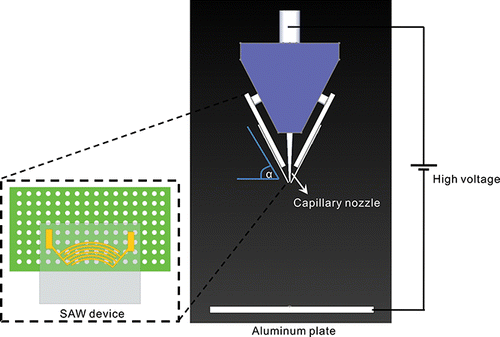
As the main part of the atomizer, the SAW unit consists of a surface acoustic wave atomizer, a device platform, and a capillary nozzle for a continuous liquid supply (). Two surface acoustic wave devices were positioned at a controlled angled slope platform in an opposing arrangement, tailoring the standing wave surface acoustic wave type device. Triangular rigid structures with three different angles (i.e., α = 20°, 40°, and 60°) for the SAW device platform were created by 3D printing (MakerBot, USA) to control the spray angle. The structures were used to support the two identical SAW devices and specifically arrange a small gap (∼1 mm) between the SAW device substrates to regulate the liquid supply for atomization. This liquid supply regulation is important to control and maintain the appropriate volume of liquid for the continuity and sustainability of the atomization process. Meanwhile, a capillary glass nozzle was used to continuously supply the liquid sample to the gap between the two SAW device substrates connected to a syringe pump (Fusion 100, Chemyx Inc., Bohlender, Germany) via the Teflon capillary tube.
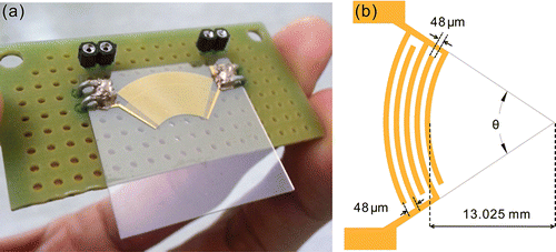
We used a progressive focused surface acoustic wave (FSAW) device type to generate a narrow surface acoustic wave beam propagation that confines the atomization process at a single direction and localized liquid-substrate contact area (). A circularly focused surface acoustic wave device with a similar basic configuration, as shown in our previous report (Darmawan and Byun Citation2014), was used for all experiment cases. The FSAW device comprised 30 pairs of interdigital transducer electrodes and 25 circular reflector electrodes with 60° and 80° eccentricities (θ) (). These eccentricities were chosen based on the consideration from the numerical study (Wu et al. Citation2005) to use intermediate FSAW eccentricity for a stable focusing SAW beam properties. The FSAW device resonance frequency was designed at 20 MHz (λSAW ≈ 198 μm) and the electrode width and pitch were set at λSAW/4 ≈ 48 μm. The IDT's electrodes were patterned with an ˜'200 nm thick Au-Cr layer on a 500 μm thick 128° Y-cut lithium niobate (LiNbO3) substrate (Yamaju Ceramics Inc., Japan) by using an UV-photolithography technique (Darmawan et al. Citation2014). First, a negative photoresist (AZ 1512) pattern was formed on the lithium niobate substrate. Sequentially, the adhesive and conductive metallic layers were deposited on the substrate using an electron beam evaporator. For the final step, the photoresist pattern was removed using a lift-off process and cleansed using the plasma grinding process to obtain clear electrode patterns.
2.2. Material Preparation
A water based PEDOT:PSS (CleviosP VP AI 4083, Heraeus) particle solution was used to characterize the generated aerosol throughout the experiment process. In our previous report, it was shown that the low PEDOT:PSS concentration is preferable to assure the continuity and sustainability of the SAW atomization process (Darmawan et al. Citation2014). The report indicated that the less dense particle concentration generates the faster atomization process. This could suppress the particle agglomeration from the recirculation flow by the acoustic streaming force during the atomization process (Raghavan et al. Citation2010; Alghane et al. Citation2011). The low particle concentration could also minimize the required input power such that the SAW device operation time could be extended with less significant effect on the resonance frequency shift due to the relatively small increase in the substrate temperature (Du et al. Citation2009; Kondoh et al. Citation2009). Therefore, in our experiment, the PEDOT:PSS solution was diluted with DI water by 1:50 volume ratio to ease the atomization process. Meanwhile, for the collector substrate, a 2 × 2 cm cut silicon wafer was used to obtain a fine contrast in the scanning electron microscope (SEM) imaging results.
2.3. Experiment Setup
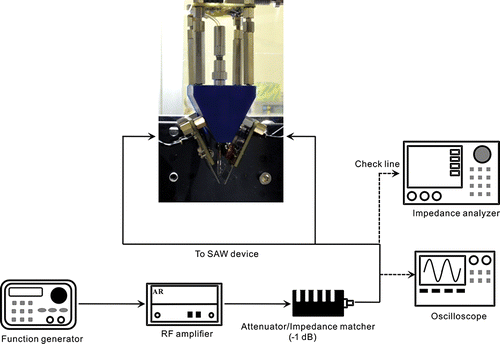
In order to generate a synchronized progressive surface acoustic wave, a maximized Vrms square AC signal was applied using a function generator (Agilent 33220A) and subsequently amplified the signal with the RF amplifier (Amplifier research 150A 100B) on two identical progressive FSAW devices. In addition, a 1 dB fixed RF attenuator was used as a matching impedance to protect the FSAW devices from the sudden high voltage supply. The resonance frequency of the FSAW device was measured using an impedance analyzer (Network analyzer R3763A). We noticed that the real FSAW device's resonance frequency was lower ∼0.15% (i.e., 19.97±0.02 MHz) than that on the design's frequency due to the inaccuracy of device fabrication. The applied voltage range used in this experiment was 74 Vpp–106 Vpp. A comprehensive experiment setup diagram is depicted in .
3. RESULTS AND DISCUSSION
3.1. Atomization Mechanism
Surface acoustic wave (SAW) atomization depends on the capillary wave droplet breakup mechanism from the hydrodynamics of the acoustic streaming phenomena. As the SAW (namely, Rayleigh wave) is propagated on the surface of the LiNbO3 substrate and made contact with a free surface liquid on the liquid-substrate boundary, the acoustic wave is then translated into the leaky acoustic wave and converted to the longitudinal pressure wave. This pressure wave, in turn, generates a recirculation flow in the liquid bulk, creating the acoustic streaming force (Qi et al. Citation2008). The force subsequently destabilizes the liquid–air interfacial boundary equilibrium, initiating the capillary waves and triggering the droplet fission, generating atomization plume (). The acoustic streaming force is expressed as the following equation (Shiokawa et al. Citation1989; Equation (Equation3[3] )):
[3] where αf is the acoustic attenuation in a fluid, A is the SAW amplitude, ω is the angular frequency, and ki is the wave number.
FIG. 4. (a) Atomization plume. (b) Schematic of the atomization generation mechanism due to the combination of Rayleigh wave at the tip of the substrate, yielding an effectively stable and strong atomization.
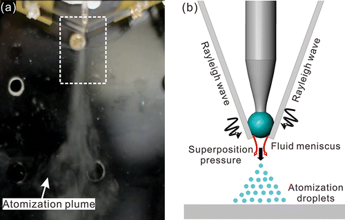
In our system, the atomization mechanism has been modified by combining the Rayleigh wave on the tip of two LiNbO3 contact substrates to generate a superposition of the SAW from the opposite directions, thus creating a similar effect to that of the standing surface acoustic wave (). Based on this mechanism, the liquid atomization could be optimized since the acoustic streaming force is two times stronger than a single progressive surface acoustic wave. Moreover, this mechanism could also stabilize the liquid position that is important to enhance the atomization efficiency. In order to increase the deposition efficiency, the electrostatic force is also utilized to direct the atomization stream to the collector substrate. Meanwhile, the liquid supply system is regulated using a nonconventional vertically supply method (in contrast to the conventional open exposure liquid supply system), which prevents the droplet movement due to the gravity force in order to effectively maintain the droplet position at the SAW resonance point.
3.2. Atomization Characterization and Optimization
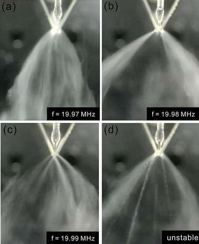
The atomization performances were characterized by conducting several parametrical studies, i.e., the operational frequency, platform angle, and liquid flow rate, to clarify the optimum and stable atomization conditions. It is known that progressive wave type of surface acoustic wave devices have a tendency to generate an atomization stream at a specific Rayleigh angle (θR ≈ 22°) due to the wave diffraction that arises from the difference between the wave propagation velocity on the substrate (cs = 3965 m/s) and the water medium (cl = 1485 m/s). The atomization direction tendency as well as the SAW mismatch resonance frequency could variously affect the spray mixture formation from two SAW devices. The inappropriate frequency setting would generate irregular spray forms and nonuniform particle distribution. Therefore, an adjustment of the resonance frequency was required to establish a typical spray condition that is a single spray mixture formation. Based on the transmission measurement using network analyzer equipment, the SAW device worked properly at a narrow frequency band 19.97–19.99 MHz. shows the effect of the device's operational frequency on the spray stream formation using a 60° device platform. We found that the atomization direction was sensitive to the small frequency alterations. depicts the occurrence of irregular spray formations (i.e., separated and chaotic) as the frequency was set to 19.98 and 19.99 MHz. These irregular spray shapes occurred as a result of unsynchronized/unbalanced acoustic radiation pressure on the tip of the SAW device substrates. An optimum spray formation (i.e., single spray, ) could be achieved as the SAW device was tuned to a frequency that generates an approximately synchronized and balanced acoustic radiation pressure profile on both substrates. However, this tuned frequency might be different from case to case, depending on several factors, such as the actual IDT's electrode dimensions, electrical device connection, and the accuracy of the substrate to substrate alignment. Therefore, as a consequence, the operational frequency should be adjusted accordingly to get an optimum spray formation. In a continuous device operation mode, an unstable liquid spray ejection was occasionally observed. This liquid ejection was most likely due to the instability of the second peak radio frequency (RF) signal (Ju et al. Citation2008) and the unstable flow from the syringe pump. The latter factor produced instability on the liquid volume supply, thereby occasionally yielding inconsistent atomization performances.
FIG. 5. Spray mixture formations according to the effect of the operational frequency. (a) Single (19.97 MHz), (b) split (19.98 MHz), (c) multiple (19.99 MHz), and (d) unstable spray stream.
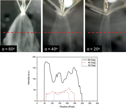
Meanwhile, the spray angle controllability was demonstrated by varying the device's platform angle at 20°, 40°, and 60°. In this section, the spray spreading is not only discussed in terms of deposition area coverage, but the spray homogeneity is also considered using image analyses. For this test, we used the same optimum operational frequency at 19.97 MHz with no significant changes on the spray formation for all platform angles. shows that the spray angle could be varied and controlled according to the platform angle. The spray angle became larger as the platform's angle was increased to 60°. However, the spray homogeneity was quite low as the leaky wave diffraction gradually spread the spray mixture based on the color intensity analyses along the spray line. On the other hand, as the platform angle was decreased to 40° and then 20°, the spray coverage was decreased by about 25% and then 60%, respectively, compared to the spray coverage of 60°. Despite the reduction on the coverage area, the spray distribution at lower angles appeared to be more uniform as the intensity profile analyses indicated less variation at the spray line. In addition, the spray stream became more stable and focused, thus allowing more precise and steady particle placement.
FIG. 6. Effect of SAW device support angle (i.e., 20°, 40°, and 60°) on the spray angle and uniformity.
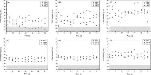
Furthermore, a temporal observation and quantitative image analysis of the atomization process were conducted at varied applied voltage, flow rate, and device eccentricity to quantitatively evaluate the atomization characteristic. For this experiment, a digital camera (Nikon D5200, Japan) operated at 30 fps was utilized to record the atomization process for 1 min. Shown in is comparison of the quantitative atomization characteristics between the 60° and 80° FSAW devices eccentricities with respect to the liquid flow rate and input voltage. The vertical axes on the graphs represent the average value of the color intensity of the spray images across a horizontal reference line. The magnitude of this value is considered as an indicator how much strong and uniform is the atomization process. The results show that the 80° FSAW device has more consistent spray performance as indicated by relatively constant average color intensity during the operation time. This implies that the device could be sustainably and continuously operated at various flow rates up to 180 μl/min. However, it should be noted that the spray appeared less uniform at 74 Vpp and 78 Vpp input voltages as the average values were consistently low due to lack of input power. On the other hand, the 60° FSAW device formed more slightly uniform spray as indicated by higher average value, despite the less stable atomization process. It is shown that the 60° device had a moderate fluctuation on the average color intensity at low input voltages (i.e., 100 Vpp and 104 Vpp) due to insufficient input power. Nevertheless, as the input voltage was set to 106 Vpp, the atomization process became more stable and uniform. The results also suggested that the 60° device requires 26%–35% higher input voltage to sustainably and continuously be operated at the same given flow rate.
FIG. 7. Atomization performance comparison of FSAW device with 60° eccentricity at (a) 100 Vpp, (b) 104 Vpp, and (c) 106 Vpp; and 80° eccentricity at (d) 74 Vpp, (e) 78 Vpp, and (f) 84 Vpp input voltages to indicate the atomization characteristics for a continuous device operation. The gray area on the graph indicates the nonatomization range within which the atomization process is stop.
3.3. Particle Deposition Characterization
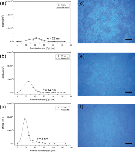
In order to characterize the aerosol sizes, the deposited particle sizes distribution was measured using image analysis (Image-J, National Institutes of Health, USA) from a field emission SEM (JEOL-7600F, USA). In a previous report, it was shown that deposition distance has a significant effect on the thin film roughness/uniformity (Darmawan et al. Citation2014). It is important to clarify the optimum deposition distance to improve the deposition quality. Therefore, at first, the particle size distribution at varied deposition distances was examined. For this test, the 60° FSAW device was used and the deposition distance was varied at 9, 11, and 13 cm from the substrate tip to the collector electrode. The results presented here show a similar trend to those of the previous report. show the comprehensive fraction particle volume distributions (df/dDp) at the varied deposition distances. The shortest deposition distance (i.e., 9 cm) showed a broad particle size range with the variance of σ ∼22 nm. This broad particle size range indeed represented a nonuniform film due to poly-disperse aerosols. However, as the deposition distance was increased to 11 cm, the particle distribution became more uniform as the variance was reduced to σ ∼14 nm. The particle size distribution was even more uniform as the deposition distance was increased to 13 cm as the range of particle size became narrow and the variance was reduced to ∼8 nm. The increasing deposition distance would properly evaporate the contained solvent such that the completely dried particles could be deposited on the collector substrate. The remaining solvent on the substrate could produce a coffee ring pattern and therefore reduce the film's uniformity as the solvent evaporates naturally. The microscope images () show the film's surface profile. These images show the resulting wetting deposition patterns occurred at the 9 and 11 cm deposition distances. The wetting pattern reduced the deposition uniformity as the particles randomly distributed.
FIG. 8. (a–c) Deposited PEDOT:PSS fraction particle volume distributions (df/dDp, fraction/cm3) at various deposition distances, i.e., 9 cm, 11 cm, and 13 cm using a 60° eccentricity FSAW device. (d–f) Corresponding microscope images of the particle deposition results, showing the effect of deposition distance to the wetting problem on the deposition results. Scale bar is 50 μm.
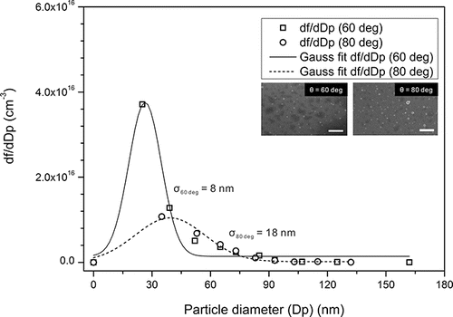
We also compare the particle size distribution of the 60° and 80° eccentricity devices to clarify the optimum deposition condition. shows a comparison of the particle distribution of the 60° and 80° devices at the optimum deposition distance, i.e., 13 cm. The measurement results showed that the 60° device had a lower particle size variance (i.e., 8 nm) compared with the 80° (i.e., 18 nm) device. Moreover, the 60° device had a narrow particle size range, which results in a more uniform film profile. The focused SEM images of PEDOT:PSS particles using the 60° and 80° devices are shown in the inset of . The increasing FSAW eccentricity reduced the width of the wave beam and the energy of the generated SAW is highly focused on the focal area (Wu et al. Citation2005). We argue that this highly focused SAW energy would generate higher inertial force, which in turn would produce a larger pinched droplets cavity. Therefore, the atomized droplets would be larger and the speed of the atomization process would increase. This larger atomized droplet size could proportionally increase the deposited particle size and even generate a wetting problem on the collector substrate as the droplets accumulate. In other words, the results suggested that although the 80° is more stable atomization process and consumes less power compared with the 60° device, it produces less uniform particle distribution due to the harsh atomization process. On the other hand, in spite of the relatively higher power consumption and less stable atomization, the 60° device generated more uniform particle size distribution due to the smooth atomization process.
4. CONCLUSIONS
In conclusion, we developed a rapid and continuous SAW atomizer system that could be used at an industrial scale. The modification of the liquid supply system and SAW device arrangement enabled a stable and sustainable atomization process, improving the conventional SAW atomizer capability. It is shown that a frequency tuning procedure is required to generate an optimum spray formation, which is generated when the acoustic radiation pressure at the tip of both SAW substrates are synchronized and balanced. Furthermore, the spray angle controllability has also been demonstrated by simply changing the angle of the device platform. Through the atomization process characterizations, we demonstrated that, at sufficient input power, the SAW spray system could produce a stable atomization process at a high input flow rate of up to ∼180 μl/min using the 60° and 80° eccentricity FSAW devices. The results show that the uniformity of particle size distribution could be controlled by the deposition distance. A uniform deposition result could be achieved as the deposition distance was increased to 13 cm. Finally, we showed that the 60° eccentricity FSAW device was able to produce a balanced particle size distribution with a small variance, though it has a slightly less stable atomization process compared to the 80° device.
Funding
This research was supported by the Basic Science Research Program through the National Research Foundation of Korea (NRF) (Grant number: 2015R1A2A1A05001829).
REFERENCES
- Alghane, M., Chen, B., Fu, Y., Li, Y., Luo, J., and Walton, A. (2011). Experimental and Numerical Investigation of Acoustic Streaming Excited by using a Surface Acoustic Wave Device on a 128 YX-LiNbO3 Substrate. J. Micromech. Microeng., 21:015005–015015.
- Alvarez, M., Friend, J. R., and Yeo, L. Y. (2008). Surface Vibration Induced Spatial Ordering of Periodic Polymer Patterns on a Substrate. Langmuir., 24:10629–10632.
- Benitez, R., Soler, J., and Daza, L. (2005). Novel Method for Preparation of PEMFC Electrodes by the Electrospray Technique. J. Power Sources., 151:108–113.
- Chono, K., Shimizu, N., Matsui, Y., Kondoh, J., and Shiokawa, S. (2004). Development of Novel Atomization System Based on SAW Streaming. Japanese J. Appl. Phys., 43:2987–2991.
- Darmawan, M., and Byun, D. (2015). Focused Surface Acoustic Wave Induced Jet Formation on Superhydrophobic Surfaces. Microfluid. Nanofluid., 18:1107–1114.
- Darmawan, M., Jeon, K., Ju, J. M., Yamagata, Y., and Byun, D. (2014). Deposition of Poly (3, 4-ethylenedioxythiophene)–Poly (styrenesulfonate)(PEDOT-PSS) Particles using Standing Surface Acoustic Waves and Electrostatic Deposition Method for the Rapid Fabrication of Transparent Conductive Film. Sens. Actuat. A Phys., 205:177–185.
- Du, X., Swanwick, M., Fu, Y., Luo, J., Flewitt, A., Lee, D., Maeng, S., and Milne, W. (2009). Surface Acoustic Wave induced Streaming and Pumping in 128 Y-cut LiNbO3 for Microfluidic Applications. J. Micromech. Microeng., 19:035016–035025.
- Friend, J., and Yeo, L. Y. (2011). Microscale Acoustofluidics: Microfluidics Driven Via Acoustics and Ultrasonics. Rev. Modern Phys., 83:647–704.
- Giménez, S., Mora-Seró, I., Macor, L., Guijarro, N., Lana-Villarreal, T., Gómez, R., Diguna, L. J., Shen, Q., Toyoda, T., and Bisquert, J. (2009). Improving the Performance of Colloidal Quantum-dot-sensitized Solar Cells. Nanotechnology., 20:295204–295209.
- Ho, J., Tan, M. K., Go, D. B., Yeo, L. Y., Friend, J. R., and Chang, H.-C. (2011). Paper-based Microfluidic Surface Acoustic Wave Sample Delivery and Ionization Source for Rapid and Sensitive Ambient Mass Spectrometry. Anal. Chem. 83:3260–3266.
- Jaworek, A. (2007). Electrospray Droplet Sources for Thin Film Deposition. J. Mater. Sci., 42:266–297.
- Jayne, J. T., Leard, D. C., Zhang, X., Davidovits, P., Smith, K. A., Kolb, C. E., and Worsnop, D. R. (2000). Development of an Aerosol Mass Spectrometer for Size and Composition Analysis of Submicron Particles. Aerosol Sci. Tech., 33:49–70.
- Ju, J., Yamagata, Y., and Higuchi, T. (2009). Thin-Film Fabrication Method for Organic Light-Emitting Diodes Using Electrospray Deposition. Adv. Mater., 21:4343–4347.
- Ju, J., Yamagata, Y., Ohmori, H., and Higuchi, T. (2008). High-frequency Surface Acoustic Wave Atomizer. Sens. Actuat. A Phys., 145:437–441.
- Kim, J.-W., Yamagata, Y., Takasaki, M., Lee, B.-H., Ohmori, H., and Higuchi, T. (2005). A Device for Fabricating Protein Chips by using a Surface Acoustic Wave Atomizer and Electrostatic Deposition. Sens. Actuat. B Chem., 107:535–545.
- Kleinstreuer, C., Zhang, Z., and Donohue, J. (2008). Targeted Drug-aerosol Delivery in the Human Respiratory System. Annu. Rev. Biomed. Eng., 10:195–220.
- Kondoh, J., Shimizu, N., Matsui, Y., Sugimoto, M., and Shiokawa, S. (2009). Development of Temperature-control System for Liquid Droplet using Surface Acoustic Wave Devices. Sens Actuat. A: Phys., 149:292–297.
- Kulkarni, P., Baron, P. A., and Willeke, K. (2011). Aerosol Measurement: Principles, Techniques, and Applications. John Wiley & Sons, New York.
- Kurosawa, M., Watanabe, T., Futami, A., and Higuchi, T. (1995). Surface Acoustic Wave Atomizer. Sens Actuat. A Phys., 50:69–74.
- Lang, R. J. (1962). Ultrasonic Atomization of Liquids. J. Acoust. Soc. Am., 34:6–8.
- Perednis, D., and Gauckler, L. J. (2005). Thin Film Deposition using Spray Pyrolysis. J. Electroceram., 14:103–111.
- Pingali, K. C., Rockstraw, D. A., and Deng, S. (2005). Silver Nanoparticles from Ultrasonic Spray Pyrolysis of Aqueous Silver Nitrate. Aerosol Sci. Tech., 39:1010–1014.
- Qi, A., Yeo, L. Y., and Friend, J. R. (2008). Interfacial Destabilization and Atomization Driven by Surface Acoustic Waves. Phys. Fluids (1994-present)., 20:074103–074116.
- Qi, A., Yeo, L., Friend, J., and Ho, J. (2010). The Extraction of Liquid, Protein Molecules and Yeast Cells from Paper Through Surface Acoustic Wave Atomization. Lab Chip., 10:470–476.
- Raghavan, R. V., Friend, J. R., and Yeo, L. Y. (2010). Particle Concentration Via Acoustically Driven Microcentrifugation: MicroPIV Flow Visualization and Numerical Modelling Studies. Microfluid. Nanofluid., 8:73–84.
- Rayleigh, L. (1882). On the Equilibrium of Liquid Conducting Masses Charged with Electricity. Lond. Edinb. Dubl. Phil. Mag. J. Sci., 14:184–186.
- Rodriguez, L., Passerini, N., Cavallari, C., Cini, M., Sancin, P., and Fini, A. (1999). Description and Preliminary Evaluation of a New Ultrasonic Atomizer for Spray-Congealing Processes. Int. J. Pharma., 183:133–143.
- Shiokawa, S., Matsui, Y., and Ueda, T. (1989). Liquid Streaming and Droplet Formation Caused by Leaky Rayleigh Waves. in IEEE Proceedings of Ultrasonics Symposium, 1989, Montreal, Quebec, Canada, pp. 643–646.
- Steirer, K. X., Reese, M. O., Rupert, B. L., Kopidakis, N., Olson, D. C., Collins, R. T., and Ginley, D. S. (2009). Ultrasonic Spray Deposition for Production of Organic Solar Cells. Solar Energy Mater. Solar Cells., 93:447–453.
- Topp, M., and Eisenklam, P. (1972). Industrial and Medical uses of Ultrasonic Atomizers. Ultrasonics., 10:127–133.
- Van Zomeren, A., Kelder, E., Marijnissen, J., and Schoonman, J. (1994). The Production of Thin Films of LiMn2O4 by Electrospraying. J. Aerosol Sci., 25:1229–1235.
- Wu, T.-T., Tang, H.-T., Chen, Y.-Y., and Liu, P.-L. (2005). Analysis and design of focused interdigital transducers. IEEE Trans. Ultrason. Ferroelect. Freq. Control., 52:1384–1392.

