ABSTRACT
Electret monolith filters have the advantage of low pressure drop and high filtration efficiency. In such filters, the filtration of submicron aerosol particles occurs as air passes through millions of microchannels. This article investigates the flow and filtration mechanisms in a representative rectangular microchannel of an electret monolith filter. An improved incompressible lattice Boltzmann method with Bhatnagar–Gross–Krook (traditionally shortened as LBGK) and lattice velocity D3Q15 model is employed to simulate no-slip and slip flows in the rectangular microchannels of a monolith filter. We considered mono-disperse submicron particles and one-way coupling (particle motion was affected by the flow, but the presence of particles did not affect the flow). Based on flow computations, the effects of key dimensionless parameters (Reynolds number, Knudsen number, Stokes number and the dimensionless length of the channel) on the total capture efficiency of mono-disperse submicron particles were investigated. Our results indicate that the optimal monolith filter should be characterized by a Knudsen number between 0.022 and 0.044, and that the dimensionless length of the channel should be between 4 and 8.
Copyright © 2016 American Association for Aerosol Research
Editor:
1. Introduction
A myriad of submicron particles are present in the air, including pollen, bacteria, and viruses. If inhaled, they may often lead to severe breathing problems, lung infection, and other diseases. Fibrous filters, which are comprised of a large number of randomly arranged fibers, are the most common means of removing particulate matter. These fibers form a dense porous material or mat which captures and retains particles. They are generally characterized by their collection efficiency and pressure drop. During the past decade, there have been many studies aimed at improving them. Many analytical and experimental investigations addressed the influences of fiber orientation on capture efficiency of a fibrous medium (Clague and Phillips Citation1997; Tomadakis and Robertson Citation2005; Tahir and Tafreshi Citation2009; Fotovati et al. Citation2010). Influences of fiber diameter on capture efficiency and pressure drop of a fibrous filter were studied by Hung and Leung (Citation2011), Leung et al. (Citation2010), and Podgorski et al. (Citation2006). High flow resistance is a disadvantage in thick dense filters that can be mitigated by using a thinner filter with charged fibers (Oh et al. Citation2002; Li and Jo Citation2010), since charging the filter improves its capture efficiency.
Unlike a fibrous filter, a monolith structure is comprised of a large number of parallel honeycomb-like channels, and has a large contact surface in a small volume and thus a much higher filtration efficiency per unit thickness. Such structures have many applications in engineering, for example in automobile purifiers and selective catalytic reduction (SCR) reactors (Yang et al. Citation2013; Ozhan et al. Citation2014). It has also been suggested to use monolith filters for particulate filtration because of a large contact surface and a small pressure drop (Wu et al. Citation2010). Using existing micro-fabrication technology, such as photo lithography, sub-micron channels of virtually any cross-sectional shape can now be fabricated on a polymer membrane. The density of these perforated holes can exceed one million channels per square centimeter (Gangadharan et al. Citation2012). Monolith filters with a high channel density will have a large contact surface area, while the diameters of the individual channels will be quite small, on the order of a micron. These two factors increase the probability of contact of the particles with the surfaces in monolith filters, resulting in high filtration efficiencies.
In addition, a quasi-permanent electrostatic field, which facilitates submicron particle capture, can be easily applied to the channels of a monolith filter made of a high molecular polymer material.
This can be done by using existing technologies such as thermal polarization and electric corona polarization. This development has led to new interest in electret monolith filters with microchannels. Using an approach similar to a single fiber model of a fibrous filter, Wu et al. (Citation2010) investigated the capture mechanisms in a monolith filter with electrostatically charged circular cross-section channels with a diameter of 2 μm, based on a single channel model of a monolith filter. Numerical simulations reported in Wu et al. (Citation2010) demonstrate a greater capture efficiency for an electrostatically charged monolith filter compared to a fibrous filter, for the same pressure drop. It should be noted that the boundary conditions for external (single fiber) and internal (monolith filter channel) flows are quite different. Wu et al. (Citation2013) studied experimentally and theoretically electrostatically charged monolith filters with over a million micro-sized channels per square centimeter; and their experiments demonstrated excellent capture efficiency in monolith filters. In order to improve the capture efficiency even further, a multistage filtration system was proposed where the flow cascades through multiple layers of monolith filters with varying channel diameters (Gangadharan et al. Citation2012). Each layer could remove particles of a specific particle size (diameter) and also function as a secondary filter for particles that escape the previous layer.
Microchannels are the fundamental units of a monolith filter. The shape, size and length of the channel influence the filtration behavior of the filter. Thus far, investigations utilizing monolith filters were limited to micron-size channels with circular cross-sections. In practice, noncircular cross-sections such as rectangular, trapezoidal, double-trapezoidal, triangular, and hexagonal, are common channel shapes that can be produced by micro-fabrication (Yang et al. Citation1999; Chen et al. Citation2006). A series of etching techniques can be used to make a variety of two-dimensional shapes with different cross-sections. Structures with rectangular cross-section channels are commonly used in engineering because the wall thickness between the channels is uniform. Since the monolith with rectangular cross-section channels can be produced with thinner walls between the channels, such structures are expected to exhibit higher porosity and a lower pressure drop. The objective of this article is to investigate the filtration properties of a monolith filter with rectangular cross-section micro-sized channels for the scenario where the inner surface of the channels has a uniform charge distribution.
Because microchannels of the monolith filter are arranged in a geometrically regular pattern, each microchannel can be thought of as a representative unit cell of the whole filter. Thus, a single microchannel can be chosen to model the monolith filter with rectangular cross-section channels. One-way coupling is assumed for the gas-solid flow in the channel, which implies that the influence of the particles on the flow is neglected. This assumption is expected to be valid if the concentration of particles is low (the suspension is dilute). As a first step toward simulating submicron particle filtration, a three-dimensional air flow in a straight rectangular microchannel is simulated by utilizing the lattice Boltzmann method (LBM). Several cross-section sizes of rectangular channels are chosen to assess the influence of the Knudsen number, Kn, on the pressure drop coefficient in the channel. A slip flow will occur in a microchannel when a Kn number is more than 0.01. Although the continuum flow in the slip flow regime can be investigated by solving numerically the Navier–Stokes equations with a slip boundary condition (Chen Citation2004), this method is very complex and typically needs many steps including coordinate transformation and velocity and pressure corrections (Renksizbulut et al. Citation2006). An alternative is to use LBM, which is a particle-based method that is easily applicable to slip flow. Its intrinsic kinetic nature makes it more computationally efficient for micro-fluidic flows (Jeong et al. Citation2006; Shi et al. Citation2007; Verhaeghe et al. Citation2009). It also produces algorithms that can be easily parallelized. Therefore, in our work the LBM approach was selected to solve the air flow in the rectangular channel. Based on flow computations, the effects of key dimensionless parameters (Reynolds number, Knudsen number, Stokes number, and the dimensionless length of the channel) on capture efficiency of mono-disperse submicron particles were investigated.
2. Air flow in the square channel
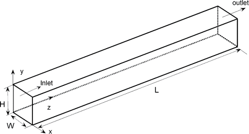
Flow simulations were performed for a single representative three dimensional channel of a monolith filter as shown schematically in . The width W and the height H of the rectangular cross-section channel are equal, and the side length of the cross-section ranges between 2 and 16 μm. The free mean path λ of air under the standard temperature and pressure is about 66 nm (Hinds Citation1999), resulting in Knudsen numbers in the range between 0.0041 and 0.03 according to, where Dh is the hydraulic diameter. Gas flows are assumed to be in the slip region when 0.01 < Kn < 0.1.
2.1. Three-dimensional lattice Boltzmann model
In LBM, the state of the fluid is characterized by the discretized density distribution of particles, fi(r, t), which describes the number of particles along the direction of the discrete velocity ei at a particular node of the lattice r, at a time t. LBM variants differ in how the collision operator is treated. Chen et al. (Citation1992) and Qian et al. (Citation1992) employed a linear relaxation approximation proposed by Bhatnagar, Gross and Krook (BGK) (Bhatnagar et al. Citation1954). This approach, which now is referred to as the lattice Boltzmann BGK model, simplified the collision operator and improved the computational efficiency tremendously. It is also considered more robust (Succi et al. Citation1993).
To simulate the three-dimensional flow in a rectangular channel, the D3Q15 (three dimensions, fifteen discrete velocities) lattice BGK model (Qian et al. Citation1992) was used. Flow in the microchannel can be considered incompressible. Hence the improved incompressible LBGK D3Q15 model proposed in Zou et al. (Citation1995) was adopted. The time evolution of the density distribution functions can be written as:where τ is the dimensionless relaxation time; ei (i = 1, 2,…, 6) are the velocity vectors with absolute value 1, which are classified as class I; and ei (i = 7, 8,…, 14) are the velocity vectors with absolute value
, which are classified as class II. The equilibrium distribution function
in this model is given by
[2] where
is the weighing factor,
,
for class I,
for class II, and the speed of sound cs equals to
. The macroscopic density and velocity of the fluid are defined by
[3] respectively.
2.2. Boundary conditions
A uniform velocity is assumed at the inlet of the microchannel, and the pressure is known and equal to 1 atm at the outlet boundary. For the velocity boundary condition, the non-equilibrium extrapolation method proposed by Guo et al. (Citation2002) was adopted. According to this method, after the streaming step, the unknown density distribution functions at the node of the boundary are comprised of an equilibrium part and a non-equilibrium part and can be expressed as:[4]
Here rw and rf are the node at the inlet boundary and the fluid node adjacent to rw, respectively. Fluid particles in the LBM solution should not be confused with solid submicron particles. Although the solid submicron particles cannot bounce off the walls due to van der Waals forces, the rules for the fluid particles in the LBM solution are different. For the outlet boundary, the bounce-back rule proposed by Zou and He (Citation1997) was applied to the non-equilibrium part of the unknown density distribution function fi:[5]
Here the direction of −i is in the opposite direction of i. The unknown density distribution functions fi at the boundary node rw after the streaming step is completed at the time t are obtained by solving Equations (Equation3[3] ) and (Equation4
[4] ) for the inlet boundary, and Equations (Equation3
[3] ) and (Equation5
[5] ) for the outlet boundary.
For the wall boundaries, a combination of specular and bounceback reflections was used (Tang et al. Citation2004; Zhang et al. Citation2005). In the bounceback reflection, a modified bounceback scheme is adopted to improve the accuracy of the calculations, that is, the collision still occurs at the boundary node (He et al. Citation1997). The unknown distribution function at the wall boundaries could be expressed according to the composite scheme[6] where
and
are the known distribution functions of the node rw at the wall corresponding to the directions of specular reflection and bounce-back, respectively:
[7]
The direction of i′ is in the specular direction of i, the direction of –i is in the opposite direction of i, and sb is the proportionality factor with a value between zero and one. sb equal to 1 means the net bounce-back scheme, and sb equal to 0 means the net specular reflection scheme. In our work, the value for sb was selected to be 0.7 for Kn numbers in the range between 0.055 and 0.16. This is justified as follows. Arkilic et al. (Citation1997) obtained an analytical solution for the slip flow in long microchannels, compared the results with high-resolution experimental data and found a good agreement. Tang et al. (Citation2004) compared their simulation results with results from Arkilic's model, and suggested that sb = 0.7 should be used to best capture the slip-velocity on the solid-gas wall for Kn numbers in the range between 0.055 and 0.16. The range for the Kn number is between 0.055 and 0.16 in our work. Hence, the same value of sb as in Tang et al. (Citation2004) was adopted.
3. Governing equation of submicron particle motion
The submicron particles inside the channel obey Newton's second law that can be written as:[8]
[9] where mp is the particle mass, Vp is the particle velocity, Fd is the drag force, Fb is the Brownian motion force, and Fe is the electrostatic force. Since the van der Waals force is a short-range force, it is significant only when the particle is close to the surface. In the numerical simulations, the van der Waals force is significant only for captured particles (Oh et al. Citation2002; Wu et al. Citation2013). We assumed that the particle cannot bounce off the walls; it is captured by the filter when the particle contacts the inner surface of the channel due to the van der Waals force.
3.1. Drag force model
The drag force Fd is caused by the relative motion between a particle and the viscous fluid. If the submicron particle meets the Stokes flow condition, Rep<<1, where the slip Reynolds number is defined as:[10] then the magnitude of the drag force is given by the Stokes law:
[11]
Here dp is the particle diameter, Vf is the fluid velocity at the location of the particle, and Cc is the Cunningham slip correction factor, which takes into account the rarefied effects during motion of a submicron particle in the gas, and is modeled as (Hinds Citation1999):[12]
3.2. Brownian motion model
The Brownian motion force Fb is modeled as a Gaussian random process, similar to the white noise process model utilized in Li and Ahmadi (Citation1992)[13] where ξ is a Gaussian random variable with zero mean and unit variance, kB is the Boltzmann constant, and T is the fluid absolute temperature. The value of Δt should be much larger than the molecular time scale and much smaller than the particle relaxation time. Here, the Brownian force is treated like any other force and the coupling between different forces can be conveniently accommodated in the numerical calculation.
3.3. Electrostatic force model
According to Podgorski (Citation2010), the electrostatic forces in the filters can be classified as the Coulomb force, the polarization force, the image force, and the dielectrophoretic force. In this article we simulate the first case, which is common to many situations involving aerosol filtration (Yang and Lee Citation2005). An electret monolith filter (that has permanent electric charges) is analyzed. It should be mentioned that submicron particles may have different electric charges, zero, one, two, or three, usually not more than four elementary units of charge (Wiedensohler Citation1988), and also may exchange charge when in contact with each other or the wall. In order to elucidate the effect that an electric charge on a particle has on capture efficiency of a monolith filter, in our work it was assumed that every particle is either neutral or carries a unit charge with an opposite sign to that on the channel's surface.
The electrostatic force Fe between the particle and the monolith filter is given as:[14] where q represents the charge on the submicron particle and E is the intensity of the electric field.
The monolith filter that we model is comprised of permanently charged polypropylene in which electric charges are distributed uniformly on the inner surface of the rectangular cross-section channels. The inner surface charge density is assumed to be 1.32 × 10⁻⁵ C/m2, which is half of the theoretical maximum surface charge density on an insulating surface (Mannan Citation2005; Wu et al. Citation2013). The intensity of the electric field at any point in the channel can be derived by using Coulomb's law (see the online supplementary information).
4. Results and discussion
4.1. Flow in the channel of a monolith filter, numerical results, and validation
The pressure drop and the capture efficiency are the two most important parameters characterizing a monolith filter. In order to validate the LBM simulations, computations of flow in the channels were carried out at Re = 1.12 for five values of the Knudsen number: 0.004, 0.008, 0.016, 0.032, and 0.064, corresponding to the side length of the channels' square cross-section of 16, 8, 4, 2, 1 μm, respectively. It is difficult to directly measure the local velocity in the channel due to its small size, so the flow field was validated indirectly by comparing the pressure loss. In the numerical computations, the distribution of the inlet flow velocity was assumed uniform. For the case of the slip flow, sb was selected to be 0.7.
The non-dimensional pressure drop along the channel is traditionally expressed in the form of the product of an apparent Fanning friction factor and the Reynolds number (Morini et al. Citation2004), as follows:[15] where Ui is the average inlet velocity,
is the pressure drop, fapp is the apparent Fanning friction factor, fappRe is the friction factor-Reynolds number product, and Dh is the hydraulic diameter:
[16]
For a square channel, Dh is equal to the side length H of the cross-section.
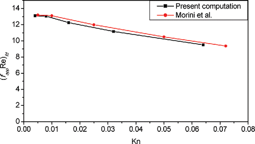
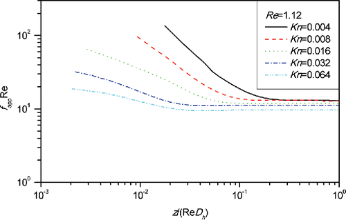
shows a comparison between the values obtained by the present calculation and analytical solution of Morini and Spiga (Citation1998) for the fully developed region. It can be seen that the computational results agree well with analytical results of Morini and Spiga (Citation1998). Furthermore, in the scenario of no-slip flow with Kn = 0.04, our numerical result is 13.1, which agrees well with the theoretical value of 13.16 (Bahrami et al. Citation2006). shows the variations of fapp Re along the axial direction at Re = 1.12 as a function of the Kn number for the square channel. It is evident that in the inlet region, the small amount of velocity slip results in a very large reduction of fapp Re, which is much larger than that in the fully developed region. The trends of our numerical results agree with those of Renksizbulut et al. (Citation2006), which were obtained by solving the Navier–Stokes equations with velocity-slip boundary conditions.
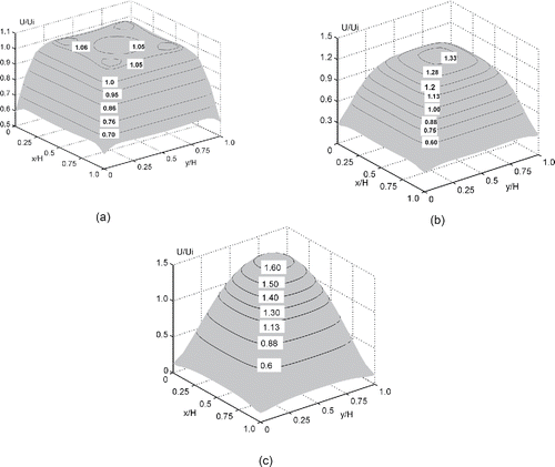
For the monolith filter under consideration, the side length of the channel cross-section was chosen to be 2 μm. In an actual monolith filter, the thickness of the monolith filter is restricted to a few microns because of the complexity of manufacturing such filters. Hence the axial length of the channel (the width of the filter) was chosen to be only 16 μm. In the fully developed region of the channel, the flow is axial, whereas in the entrance region the flow is three-dimensional. In order to better understand the flow in the channel, we show the development of the velocity profile in the entrance region in . It can be seen that at the axial location of z/(HRe) = 0.087 () the maximum values of the velocity contour occur near the four corners of the channel, not at the center of the channel. As air flows downstream, the air velocity in the channel core region increases gradually, while that in the channel periphery region drops gradually until the flow becomes fully developed. At the axial location of z/(HRe) = 0.217 (), the maximum velocity is in the channel centerline. There are large velocity gradients near the walls, resulting in correspondingly large friction coefficients early in the entrance region in . Flow is fully developed at the axial location of z/(HRe) = 0.304 (); it is characterized by relatively low velocities and velocity gradients near channel walls compared to the situations displayed in . In addition, we can see further from that the downstream slip velocity takes its minimum value at the four corners of the cross-section. According to numerical results of Renksizbulut et al. (Citation2006), which were obtained by solving the Navier–Stokes equations with a slip boundary condition, this phenomenon becomes more pronounced at larger Reynolds numbers.
Figure 4. Velocity contours in the square channel at Re = 1.12 and Kn = 0.032. (a) z/(HRe) D 0.087; (b) z/(HRe) D 0.217; (c) z/(HRe) D 0.304.
The above simulation results show that the length of the entrance region is ∼ 0.7 μm. The entrance length L can be calculated by the following formula (Duan and Muzychka Citation2010):[17] where σ denotes the tangential momentum accommodation coefficient. The most usual conditions correspond to
. The entrance length L predicted by Equation (Equation16
[16] ) is 0.63 μm, which agrees with our numerical results. Therefore, although there are large fapp Re values at the entrance region, the contribution of this region to the overall pressure drop is very small because of the short length of the entrance region compared to the channel length.
4.2. Effects of key parameters on capture efficiencies
The deposition of submicron particles in the channel is caused by the simultaneous action of inertia, Brownian diffusion, and electrostatic forces. The dominating factors in particle deposition are determined by parameters controlling particle motion and fluid flow, such as the diameter and density of particles, the velocity and viscosity of the fluid, the cross-section size and length of the channel, as well as charges on the particles and charge density on the surface of the channel. To elicit more general results in terms of the influence of other parameters, the dimensionless groups Re, Kn, L/H, and St (the Stokes number), defined as[18] were employed and their effects on capture efficiency were analyzed.
The relaxation time of the particle, , is given by
[19]
In this study, we assumed that the channel surface has a charge of half of the theoretical maximum surface charge density on an insulating surface. The particles were assumed to be either not charged or carry one elementary charge. The flow entering the channel is assumed to have a uniform velocity. Dimensions and physical constants used in the simulations are shown in .
Table 1. Simulation parameters.
4.2.1. Effects of the Reynolds number
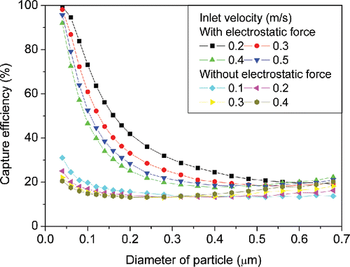
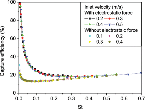
The key non-dimensional parameter that governs the flow in the rectangular straight channel is the Reynolds number, in which the inlet air average velocity is used as a velocity scale. Five inlet velocities of 0.1, 0.2, 0.3, 0.4, and 0.5 m/s, corresponding to values of the Reynolds number of 0.011, 0.022, 0.033, 0.044, and 0.055, respectively, were used to assess the influence of Re on the total filtration efficiency of the electret monolith filter at Kn = 0.032 and L/H = 8. As shown in , along with the particle size, the inlet velocity also has a significant effect on capture efficiency for charged and uncharged particles. In the presence of an electrostatic force, the total capture efficiency was reduced noticeably by an increase in the inlet velocity, which indicates that in the presence of electrostatic force capture efficiency strongly depends on particle residence time in the channel.
Although using the particle diameter as the independent variable is intuitive, it does not reflect the interaction between the particle and the fluid. The Stokes number quantifies this interaction much better as it represents the ratio of the relaxation time of the particle to the characteristic time of the flow. is derived from data used to plot , but now the Stokes number is used as the independent variable. It can be seen that when the Stokes number is plotted along the horizontal axis, the monolith filter efficiency is insensitive to the Reynolds number in the range we investigated, whether or not there is an electrostatic force. This phenomenon, which we now found for monolith filters, was previously reported for inertial impactors, which are devices that classify aerosol particles by their aerodynamic diameters (Rader and Marple Citation1985).
The deposition of particles is caused by the simultaneous action of diffusion, inertial impaction, and electrostatic attraction. The relative magnitude and importance of these forces in the particle capture process changes with the Stokes number. The Stokes number range may be roughly divided into three regions. First we analyze the scenario with no electrostatic force. The efficiency drops rapidly with an increase of the Stokes number when the Stokes number is less than 0.05. The dominating deposition mechanism here is diffusion and the particle inertia can be neglected. The efficiency drops gradually with increasing Kn when the Stokes number is between 0.05 and 0.1, in which case the dominating deposition mechanisms are diffusion and inertia. If the Stokes number is larger than 0.1, the efficiency increases with increasing values of Kn, and in this case the inertia represents the dominant mechanism of particle capture. For the scenario which includes an electrostatic force, the diffusion and electrostatic forces cause particle deposition at Stokes numbers less than 0.05; however, the capture efficiency drops rapidly as the Stokes number increases. When the Stokes number is between 0.05 and 0.2, the diffusion, electrostatic force, and inertia are all at play, while above 0.2 the inertia force becomes dominant.
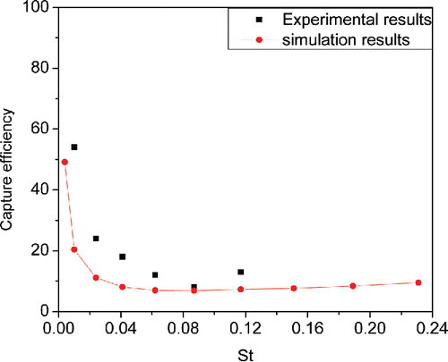
To validate the computational results, the experimental data from Wu et al. (Citation2013) were compared with our computational results obtained for the same conditions as Wu's experiment (Kn = 0.0176, L/Dh = 3.74). shows that the particle capture efficiency obtained from experiment is approximately 10.9% higher than our computational results. One possible explanation is that the particle capture efficiency reported in the experimental results includes depositions on the front face of the monolith filter, whereas our simulations considered only depositions inside the microchannel. Both are close if experimental capture efficiency is reduced proportionally, since, according to the computation result of Wu et al. (Citation2013), over 15% in the total capture efficiency is due to particle deposition on the front face of the filter.
Figure 7. Comparison of computational results obtained in this article and experimental results reported in Wu et al. (Citation2013).
4.2.2. Effects of Kn number
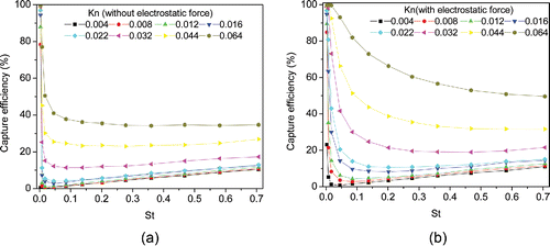
The Kn number of the square channel is inversely proportional to the side length of the cross-section size of the square channel. To investigate the effects of the Kn number on filtration efficiency, we used eight values of the side length of the channels' square cross-section (16, 8, 6, 4, 3, 2, 1.5, and 1 μm), corresponding to Kn number of 0.004, 0.008, 0.012, 0.016, 0.022, 0.032, 0.044, and 0.064, respectively. The other parameters are kept at values given in . shows plots of capture efficiency versus the Stokes number for eight values of Kn for two scenarios, (a) without the electrostatic force, and (b) with the electrostatic force. It can be seen that for the Kn number less than 0.022 (corresponding to 3 μm for the side length of the channel cross-section), the filtration efficiency does not increase quickly as the Kn number increases, whether or not there is the electrostatic force on the particles. However, capture efficiency increases quickly as the Kn number increases when Kn is larger than 0.022. Based on this consideration, we suggest that Kn should be chosen between 0.022 and 0.044 for an optimal monolith filter. The predicted effect of the Knudsen number is in good agreement with data reported in Wu et al. (Citation2013).
4.2.3. Effects of L/H
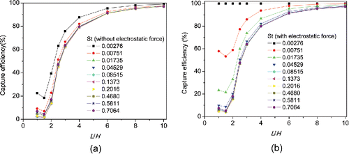
To investigate the effects of L/H, the value of the Kn number was set to 0.032 because above this value the filter starts to reach a high capture efficiency, as shown in . The other parameters are the same as in . displays capture efficiency versus the side length of the channel for different Stokes numbers with and without the electrostatic force. It is observed that for all Stokes numbers, the capture efficiency increases slowly with the increase of L/H when L/H is larger than 8, whereas when L/H is between 1.5 and 4, the capture efficiency drops rapidly with the decrease of L/H. On the other hand, the pressure drop, an important parameter characterizing filter performance, increases notably with an increase in L/H. Considering this factor, we suggest that L/H should be chosen between 4 and 8 for an optimal monolith filter.
5. Conclusions
In this article, an air flow with no-slip and slip boundary conditions inside a rectangular microchannel of an electret monolith filter was investigated using an improved incompressible LBGK D3Q15 model. Our numerical results show that the friction factor-Reynolds number product in the developing and fully developed regions decreases monotonically with an increase in the Knudsen number. Our numerical results obtained by the LBM solution agree with those obtained by solving the Navier–Stokes equations with a slip boundary condition.
Effects of the key parameters, such as the Reynolds number, the Knudsen number, and the dimensionless length L/H on capture efficiency for a monolith filter were investigated. Our numerical results show that the capture efficiency is insensitive to the Reynolds number when the Stokes number is plotted along the horizontal axis. Capture efficiency increases quickly as Kn increases when Kn is larger than 0.022. Capture efficiency increases slowly as L/H increases when L/Dh is larger than 8, whereas when L/H is between 1.5 and 4, capture efficiency decreases rapidly as L/H decreases. Taking into account the fact that the pressure drop in the filter should be small to avoid large forces that can rupture the filter and the complexity of manufacturing monolith filters with long channels, we suggest that the optical monolith filter should be characterized by Knudsen numbers between 0.022 and 0.044, and that the dimensionless length of channel should be between 4 and 8.
UAST_1218437_Supplementary_File.zip
Download Zip (47.3 KB)Funding
AVK gratefully acknowledges the support of the Alexander von Humboldt Foundation through the Humboldt Research Award.
References
- Arkilic, E. B., Schmidt, M. A., and Breuer, K. S. (1997). Gaseous Slip Flow in Microchannels. J. Microelectromechanical Syst., 6:167–178.
- Bahrami, M., Yovanovich, M. M., and Culham, J. R. (2006). Pressure Drop of laminar, Fully Developed Flow in Microchannels of Arbitrary Cross-Section. ASME J. Fluids Eng., 128:1034–1044.
- Bhatnagar, P. L., Gross, E. P., and Krook, M. (1954). A Model for Collision Processes in Gases. I. Small Amplitude Processes in Charged and Neutral One-Component Systems. Phys. Rev., 94:511–525.
- Chen, C.-S. (2004). Numerical Method for Predicting Three-Dimensional Steady Compressible Flow in Long Microchannels. J. Micromech. Microeng., 14:1091–1100.
- Chen, H., Chen, S., and Matthaeus, W. H. (1992). Recovery of the Navier–Stokes Equations Using a Lattice-Gas Boltzmann Method. Phys. Rev. A, 45:5339–5342.
- Chen, P. J., Shih, C. Y., and Tai, Y. C. (2006). Design, Fabrication and Characterization of Monolithic Embedded Parylene Microchannels in Silicon Substrate. Lab. Chip, 6:803–810.
- Clague, S. D., and Phillips, R. J. (1997). A Numerical Calculation of the Hydraulic Permeability of Three Dimensional Disordered Fibrous Media. Phys. Fluids, 9:1562.
- Duan, Z., and Muzychka, Y. S. (2010). Slip Flow in the Hydrodynamic Entrance Region of Circular and Noncircular Microchannels. J. Fluids Eng., 132:011201.
- Fotovati, S., Tafreshi, H. V., and Pourdeyhimi, B. (2010). Influence of Fiber Orientation Distribution on Performance of Aerosol Filtration Media. Chem. Eng. Sci., 65:5285–5293.
- Gangadharan, S., Kuznetsov, A. V., Zhu, H., Hinestroza, J., and Jasper, W. J. (2012). Modeling of Cross-Flow Across an Electrostatically Charged Monolith Filter. Particul. Sci. Technol., 30:461–473.
- Guo, Z. L., Zheng, C. G., and Shi, B. C. (2002). Non-Equilibrium Method for Velocity and Pressure Boundary Conditions in the Lattice Boltzmann Method. Chinese Phys., 11:366–374.
- He, X. Y., Zou, Q. S., Luo, L. S., and Dembo, M. (1997). Analytic Solutions of Simple Flows and Analysis of Nonslip Boundary Conditions for the Lattice Boltzmann BGK Model. J. Stat. Phys., 87:115–136.
- Hinds, W. C. (1999). Aerosol Technology Property, Behavior, and Measurement of Airborne Particles, 2nd ed. Wiley, New York.
- Hung, C. H., and Leung, W. W. F. (2011). Filtration of Nano-Aerosol using Nanofiber Filter Under Low Peclet Number and Transitional Flow Regime. Sep. Purif. Technol., 79:34–42.
- Jeong, N., Lin, C. L., and Choi, D. H. (2006). Lattice Boltzmann Study of Three-Dimensional Gas Microchannel Flows. J. Micromech. Microeng., 16:1749–1759.
- Leung, W. W. F, Hung, C. H., and Yuen, P. T. (2010). Effect of Face Velocity, Nanofiber Packing Density and Thickness on Filtration Performance of Filters with Nanofibers Coated on a Substrate. Sep. Purif. Technol., 71:30–37.
- Li, A., and Ahmadi, G. (1992). Dispersion and Deposition of Spherical Particles from Point Sources in a Turbulent Channel Flow. Aerosol Sci. Tech., 16:209–226.
- Li, K., and Jo, Y. M. (2010). Dust Collection by a Fiber Bundle Electret Filter in an MVAC System. Aerosol Sci. Tech., 44:578–2010.
- Mannan, S. (2005). Lees' Loss Prevention in the Process Industries, 3rd ed. Butterworth-Heinemann, Oxford, UK.
- Morini, G. L., and Spiga, M. (1998). Slip Flow in Rectangular Microtubes. Microscale Thermophys. Eng., 2:273–282.
- Morini, G. L., Spiga, M., and Tartarini, P. (2004). The Rarefaction Effects on the Friction Factor of Gas Flow in Microchannels. Superlattices Microstruct., 35:587–599.
- Oh, Y. W., Jeon, K. J., Jung, A. I., and Jung, Y. W. (2002). A Simulation Study on the Collection of Submicron Particles in a Unipolar Charged Fiber. Aerosol Sci. Tech., 36:573–582.
- Ozhan, C., Fuster, D., and Costa, P. D. (2014). Multi-Scale Flow Simulation of Automobile Catalytic Converters. Chem. Eng. Sci., 116:161–171.
- Podgorski, A. (2010). Protection of the Respiratory System Against Nanoparticles Inhalation. in Nanoparticles in Medicine and Environment, J. C. M. Marijnissen and L. Gradon´, eds. Springer, Dordrecht, Chapter 14, pp. 251–277.
- Podgorski, A., Bałazy, A., and Gradon´, L. (2006). Application of Nanofibers to Improve the Filtration Efficiency of the Most Penetrating Aerosol Particles in Fibrous Filters. Chem. Eng. Sci., 61:6804–6815.
- Qian, Y. H., D'Humières, D., and Lallemand, P. (1992). Lattice BGK Models for Navier–Stokes Equation. Europhys. Lett., 17:479–484.
- Rader, D. J., and Marple, V. A. (1985). Effect of Ultra-Stokesian Drag and Particle Interception on Impaction Characteristics. Aerosol Sci. Technol., 4:141–156.
- Renksizbulut, M., Niazmand, H., and Tercan, G. (2006). Slip-Flow and Heat Transfer in Rectangular Microchannels with Constant Wall Temperature. Int. J. Therm. Sci., 45:870–881.
- Shi, Y., Zhao, T. S., and Guo, Z. (2007). Lattice Boltzmann Simulation of Dense Gas Flows in Microchannels. Phys. Rev. E, 76:016707.
- Succi, S., D'Humières, D., Qian, Y. H., and Orzag, S. A. (1993). On the Small-Scale Dynamical Behavior of Lattice BGK and Lattice Boltzmann Schemes. J. Sci. Comput., 8:219–230.
- Tahir, M. A., and Tafreshi, H. V. (2009). Influence of Fiber Orientation on the Transverse Permeability of Fibrous Media. Phys. Fluids, 21:083604.
- Tang, G. H., Tao, W. Q., and He, Y. L. (2004). Lattice Boltzmann Method for Simulating Gas Flow in Micro-Channels. Int. J. Mod. Phys. C, 15:335–347.
- Tomadakis, M., and Robertson, J. T. (2005). Viscous Permeability of Random Fiber Structures: Comparison of Electrical and Diffusional Estimates with Experimental and Analytical Results. J. Compos. Mater., 39:163–188.
- Verhaeghe, F., Luo, L. S., and Blanpain, B. (2009). Lattice Boltzmann Modeling of Microchannel Flow in Slip Flow Regime. J. Comput. Phys., 228:147–157.
- Wiedensohler, A. (1988). An Approximation of the Bipolar Charge Distribution for Particles in the Submicron Range. J. Aerosol Sci., 19:387–389.
- Wu, M., Kuznetsov, A. V., and Jasper, W. J. (2010). Modeling of Particle Trajectories in an Electro-Statically Charged Channel. Phys. Fluids, 22:043301.
- Wu, M., Jasper, W. J., Kuznetsov, A. V., Johnson, N., and Rasipuram, S. C. (2013). Submicron Particle Filtration in Monolith Filters—A Modeling and Experimental Study. J. Aerosol Sci., 57:96–113.
- Yang, X., Yang, J. M., Tai, Y. C., and Ho, C. M. (1999). Micromachined Membrane Particle Filters. Sensor. Actuator., 73:184–191.
- Yang, J., Ma, H., Yamamoto, Y., Yu, J., Xu, G., Zhang, Z., and Suzuki, Y. (2013). SCR Catalyst Coated on Low-Cost Monolith Support for Flue Gas Denigration of Industrial Furnaces. Chem. Eng. J., 230:513–521.
- Yang S., and Lee, G. W. M. (2005). Filtration Characteristics of a Fibrous Filter Pretreated with Anionic Surfactants for Monodisperse Solid Aerosols. J. Aerosol Sci., 36:419–37.
- Zhang, Y., Qin, R., and Emerson, D. R. (2005). Lattice Boltzmann Simulation of Rarefied Gas Flows in Micro-Channels. Phys. Rev., 71:47702.
- Zou, Q., and He, X. (1997). On Pressure and Velocity Flow Boundary Conditions and Bounceback for the Lattice Boltzmann BGK Model. Phys. Fluids, 9:1591–1598.
- Zou, Q., Hou, S., Chen, S., and Doolen, G. D. (1995). An Improved Incompressible Lattice Boltzmann Model for Time—Independent Flows. J. Stat. Phys., 81:35–48.

