
 ?Mathematical formulae have been encoded as MathML and are displayed in this HTML version using MathJax in order to improve their display. Uncheck the box to turn MathJax off. This feature requires Javascript. Click on a formula to zoom.
ABSTRACT
The optimized blast furnace design is the prerequisite for low-carbon smelting. The salamander depth and bosh angle are the key parameters, which determine the blast furnace longevity. In this paper, the physical and mathematical force model of deadman and cooling stave was established. The relationship between operating parameters and the salamander depth, as well as bosh angle, was analysed, and the gas flow scouring curve was proposed. The following results were obtained: first, the reasonable salamander depth/hearth diameter ratio and bosh angle should be 23∼25% and 73°∼75° in China, respectively. Second, the key factors that influence the floatation of deadman and wear of the cooling stave are the deadman voidage and the slag crust thickness, respectively. Lastly, it is necessary to adjust some measures such as coke ratio, blow velocity and tuyere length. This paper is meant for optimizing the design of blast furnace.
Introduction
As an important pillar of the national economy, the iron and steel industry shoulders the responsibility of saving energy and reducing energy consumption. Blast furnace is vital equipment in this industry. With the improvement of the technology, low-carbon smelting and long-life blast furnace are the future directions in China [Citation1–3]. At present, the safety of hearth and bosh has become a key link limiting a whole campaign life of the blast furnace. The initial design of the blast furnace is the innate basis, which is the fundamental guarantee of low-carbon smelting [Citation4]. The optimal design of the blast furnace involves many aspects, especially the salamander depth and bosh angle that are paid close attention by domestic and foreign researchers.
The initial design of the salamander depth and bosh angle is important, which will play an important role in the stable operation of the blast furnace. The salamander depth has a direct relationship with deadman floating state [Citation5]. When salamander depth is shallow and deadman is sitting in the bottom, molten iron concentrates in the bottom edge of deadman, which is also called the furnace corner. It leads to high temperature and no stable skull at bottom corners because of strong circulation [Citation6], forming the elephant-foot erosion. When salamander depth is too deep and deadman is floating heavily, the intermediate sidewall region between taphole and bottom is locally eroded although molten iron flow at bottom corners lessens resulting in mumps’ face-type erosion. Appropriate salamander depth provides favourable conditions for the best state of the deadman, such that deadman is floating slightly. The initial design of the bosh angle is important as it will play an integral part in determining the condition of the bosh as the furnace campaign progresses. The bosh acts as the interface between belly and hearth which is a critical zone, which faces severe process loads such as fluctuating high temperatures and abrasion and erosion from the descending burden and ascending gas [Citation7–9]. Reasonable bosh angle must be good for burden motion, reasonable gas flow distribution and the physical chemical process. It creates great conditions for low-carbon smelting and blast furnace longevity.
Up to now, the profile of blast furnace is designed by the experienced judgment and mathematical simulation [Citation10–12]. M.Vångö et al. [Citation13] proposed a dynamic void fraction model to study the dynamic and CFD-DEM method to simulate the dynamic floating behaviour of deadman during iron and salg drainage. Zhu et al. [Citation14] proposed that large normal stresses are mainly observed in the lower central part of the blast furnace and small normal stresses in the vicinity of the raceway, which is supported by a computational fluid dynamics-discrete element method. S. A. Zaïmi et al. [Citation15] proposed that the existence of deadman in the blast furnace and analysed the shapes of deadman zone are closely related to designed profile such as bosh and hearth, which is supported by hypo-plasticity theory. Zhang et al. [Citation16] analysed the influence of blast furnace profile on burden descend and stress field through the three-dimensional discrete element method, and proposed the appropriate bosh angle is about 78°.
In this paper, the influence of salamander depth and bosh angle on the blast furnace longevity was analysed. The appropriate initial designed values and measures taken in the actual production were proposed. Based on the previous research, this paper optimizes the design parameters of the blast furnace systematically and provides support for long life, low-carbon smelting.
Force model
The salamander depth and bosh angle have a direct relationship with the floating state of deadman and the friction degree, respectively. The force analysis of deadman in hearth and the cooling stave from belly to bosh is shown in .
Figure 1. Force model of the deadman and the cooling stave.
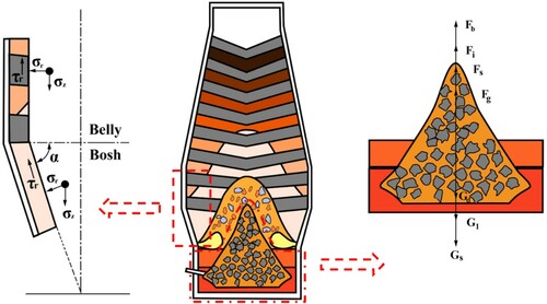
Force model of the deadman
Based on the relationship between the salamander depth and the floating state of deadman, the corrosion morphology of the hearth, the appropriate salamander depth that the deadman always floats slightly in the molten iron in actual production are further clarified, and the stress state of the deadman is analysed.
The deadman is mainly affected by the pressure of the upper burden, its own gravity, the buoyancy of the blast furnace gas, the buoyancy of the slag, the buoyancy of the molten iron and the friction force of burden [Citation17–19] According to the force balance, the pressure of the upper burden on the deadman is numerically equal to the gravity of the lumpy zone, the cohesive zone and the dripping zone. Because the particle size and composition of the coke in the dripping zone are quite different from in the lumpy zone and the cohesive zone, the force analysis is done separately.
The gravity of dripping zone Gd
(1)
The gravity of lumpy zone Gl
The gravity of deadman Gs
The buoyancy of the blast furnace gas Fg
The buoyancy of the slag Fs
The buoyancy of the molten iron Fi
The buoyancy of the molten iron is calculated in two parts. One is the molten iron with coke, and the other is the molten iron without coke, which is under the bottom of deadman.
(8)
(8) where ρi is the molten iron density, kg m−3; hi is the height of deadman immersed in molten iron, m; hf is the floating height of deadman, m.
The friction of cooling stave Fs
Based on the relationship between the salamander depth and the height of the deadman immersed in molten iron, the floating height, it can be concluded that
(10)
(10) where hf is the depth of salamander, m.
By ensuring and
, the deadman can be guaranteed to float in the molten iron.
Substituting into the above formula, it can be concluded that the depth of salamander ensuring deadman floating in the molten iron is
(11)
(11) The calculation needs to meet the following assumptions, based on the blast furnace temperature field simulation and blast furnace hearth dissection [Citation20–29].
The blast furnace is full of burden that is only composed of ore and coke.
The floating height of the deadman should be at least 100 mm.
There are no coke in the deadman that not immersed in molten iron.
The deadman is divided into two parts. The upper cone inclination angle is about 60°, and the lower truncated cone inclination angle is about 30°.
The interface of the upper and lower parts of the deadman is located 1.5 m below the taphole centreline.
The voidage of the centre and the edge of the deadman are different. The centre and the edge account for 1/5 and 4/5 of the total area, respectively. The centre and edge voidage are about 0.35 and 0.50, respectively.
The dripping zone is entirely composed of coke, and its voidage is nearly equal to that of deadman.
The volume of the slag on both sides of the truncated cone at the lower part of the deadman is small, so this part of the slag is ignored. The buoyancy of the slag is calculated based on the horizontal section cylinder.
The shape of each area of the blast furnace is treated as ideal.
Based on the assumptions and production experience, the force analysis parameters of the deadman are shown in .
Table 1. The force analysis parameters of the deadman.
Force model of the cooling stave
Based on Jensen's equation for calculating the burden pressure of the silo in powder mechanics [Citation30,Citation31], the definition of equivalent bosh angle is introduced to analyse the stress state of cooling stave from belly to bosh of the blast furnace.
As shown in , the front end of the tuyere is connected to the top of bosh, and the included angle with the horizontal plane is the equivalent bosh angle.
Figure 2. Schematic diagram of equivalent bosh angle.
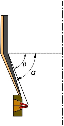
The relationship between the equivalent bosh angle and the actual bosh angle is as follows:
(12)
(12) where β is the equivalent bosh angle, °; h is the height of bosh, m; α is the actual bosh angle of bosh, °; l is the actual length of tuyere.
(13)
(13)
(14)
(14) where σz, σr are the primary stress of cooling stave, kPa; K is the scale factor of σz and σr; τr is the shear stress caused by σr; μ is the friction factor of burden and the cooling stave.
The burden is active during the descending process
(15)
(15) where φ is the angle of internal friction °.
The burden is passive during the descending process
(16)
(16) For cylinders
(17)
(17) where γ is the weight density of burden, N m−3; D is the diameter of cylinder, m; z is the height of a certain section of the cylinder, m. For cone, suppose
(18)
(18) where δ is half of cone angle, °, that is δ = 90°−α.
If ,
(19)
(19) If
,
(20)
(20) where σz is the primary stress at initial height, kPa; H is the total cone height, m; z is the height of a certain section of the cone, m.
The calculation needs to meet the following assumptions, based on production experiences.
According to the stress transition state generally occurs at the interface of the cylinder and cone [Citation32], the belly burden and bosh burden are active and passive, respectively.
The initial primary stress of cooling stave in belly is 0, and the length of tuyere is 550 mm.
Based on the assumptions, a 3000 m3 blast furnace in China is selected, whose force analysis parameters of cooling stave from belly to bosh are shown in .
Table 2. The force analysis parameters of the cooling stave.
Reasonable depth of salamander
Based on the data in , the calculation results from formula (1) to (11) are shown in . The reasonable salamander depth/hearth diameter ratios are 23.89, 24.19, 24.72 and 25.13% in some typical blast furnaces with volumes of 2000, 3000, 4000, 5000 m3, respectively, which guarantee the floating height of deadman is greater than 100 mm. It indicates that the reasonable ratio increases gradually with the increase of blast furnace volume.
Figure 3. Diagram of calculation and actual comparison of the salamander in China.
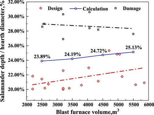
Fitting the designed salamander depth of some blast furnaces in China, it can be seen that the designed salamander depth/hearth diameter ratio increases with the increase of the blast furnace volume, which is consistent with the calculated results. Only a few blast furnaces with a designed value of about 5000 m³ are close to the calculated trend line, and most of them are significantly lower than the calculated value.
After fitting of the salamander depth of some blast furnaces at the end of the campaign in China, it can be seen that the designed salamander depth/hearth diameter ratio is mainly between 28.35 and 28.97%. It tends to decrease with the increase of the blast furnace volume, which is opposite to the trend of designed depth and force analysis calculation. It shows that the shallower the designed salamander, the more vulnerable the blast furnace bottom refractory material for erosion and damage. In other words, the salamander depth is deep enough, the erosion of blast furnace bottom will be greatly reduced. However, it does not mean that the salamander depth is deepened unlimitedly. The salamander is too deep to exceed the salamander depth/hearth diameter ratio of the damaged blast furnace, the ferrostatic pressure becomes very large, which will promote the osmosis of the molten iron to the hearth carbon bricks and ceramic cups. It, in turn, leads to the damage of the hearth.
Therefore, the designed salamander depth is reasonable, the above two situations can be effectively avoided. There may be even only slight or zero erosion.
The designed salamander depth in the world is shown in [Citation33,Citation34]. The designed salamander depth/hearth diameter ratio in Japanese blast furnaces is mainly between 14.18 and 17.11% and 27.53 and 30.00%. The latter are new blast furnaces, which show that the salamander is deepening continuously in Japan. The salamander depth is between 21.00 and 24.32% in Korea. The salamander depth is about 20.00% in German, which cannot represent the overall situation of Germany blast furnace. It is not neglected that P.W. considered the designed salamander depth of 26.8% is better than 15.5% and the critical depth is 31.1% when dissecting the German blast furnace [Citation33]. The designed salamander depth is 27.0% in the Britain. The salamander depth is concentrated between 20.00 and 22.93%, and only a few can get 25.32% in China. In other words, the salamander depth is relatively shallow.
Figure 4. The designed salamander depth in the world.

Comprehensively considering the comparative analysis of the calculated salamander depth, the designed depth and the damaged depth and the actual trend of the salamander depth in the world, it is necessary to deepen the designed salamander depth for low-carbon smelting and longevity in China. It can ensure deadman always floats in the molten iron and reduces the effect of circulation erosion. However, considering avoiding osmosis caused by the excessive ferrostatic pressure, it can be deepened to 23–25%.
In the calculation, it is found that the salamander depth is related to the coke ratio, the voidage of lumpy zone, the blow velocity and the voidage of deadman. Therefore, the actual salamander depth can be adjusted by adjusting the above parameters in actual production.
There is an indirect or direct relationship between the coke ratio, the voidage of lumpy zone, the blow velocity and the voidage of deadman. In the end, these parameters will be reflected in the voidage of deadman. With the increase of the coke ratio, the amount of iron ore and the voidage of lumpy zone decreases relatively. The internal friction of the coke will decrease in the lumpy zone, which ensures the strength. The coke continues to descend to the cohesive zone, dripping zone and tuyere raceway. The coke is gradually pulverized under the effects of high thermal stress, alkali metal catalysis, high velocity gas, molten iron and molten slag scouring. However, due to its high strength, the pulverization is small and the voidage of deadman is relatively high. Increasing the blow velocity is conducive to blowing out more powder that was brought in by the raw fuel. It improves the air and liquid permeability of deadman and increases the voidage of deadman [Citation35] Therefore, it is necessary to analyse the influence of the voidage of deadman on the actual salamander depth.
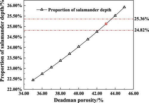
5000 m3 blast furnace is selected for calculation and analysis, and the results are shown in . The greater the voidage of deadman, the deeper the salamander. Combining , the salamander depth/hearth diameter ratio is controlled between 24.82 and 25.36%. The corresponding voidage of deadman is 0.42∼0.44. Therefore, voidage of deadman can be adjusted to about 0.43 by adjusting parameters such as the coke ratio, the voidage of lumpy zone and the blow velocity in the actual production. It helps to extend the life of the blast furnace.
Figure 5. Influence the salamander depth and the voidage of deadman.
Reasonable bosh angle
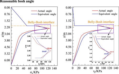
Based on the data in , the calculation results from formulas (12) to (20) are shown in . In the actual hearth angle model, as the burden descends from the belly, both σz and τr gradually increase first, then they suddenly increase at the interface of the belly and bosh. After that, they reach the maximum values as 125.44 and 131.71 KPa, respectively. Finally, they decreased rapidly and then slowly. In the equivalent angle model, the trend of σz and τr is almost the same as the actual ones. There are two differences. One is that the maximum value of σz and τr is less than the corresponding value of the actual bosh angle model. The other is that their increasing ranges are less than the corresponding ones in the actual bosh angle model. Therefore, the force on the cooling stave can be adjusted by lengthening the tuyere in actual production.
Figure 6. Influence of the stress with the descend position of the burden.
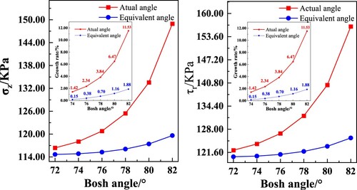
The maximum positions of σz and τr are selected to analyse the influence of bosh angle and stress distribution of the blast furnace. The results are shown in . The increasing trend of σz and τr with the bosh angle is basically the same, which is caused by the certain proportional relationship between σz and τr. When the bosh angle increases from 73° to 75°, σz and τr increase slowly and they remain almost unchanged in the equivalent bosh angle model. When the bosh angle increases to 76°, it shows a rapid rising trend. After that, the stress increases faster and faster. It indicates that bosh angle of 76°is a turning point of the stress of the cooling stave. The stress and rising trend of the equivalent furnace bosh angle are significantly lower than the actual one. It shows once again that the force on the cooling stave can be adjusted by lengthening the tuyere in actual production. In other words, reducing the bosh angle is beneficial to reduce the direct wear and tear of the burden on the cooling stave.
Figure 7. Influence of bosh angle and stress distribution of the blast furnace.
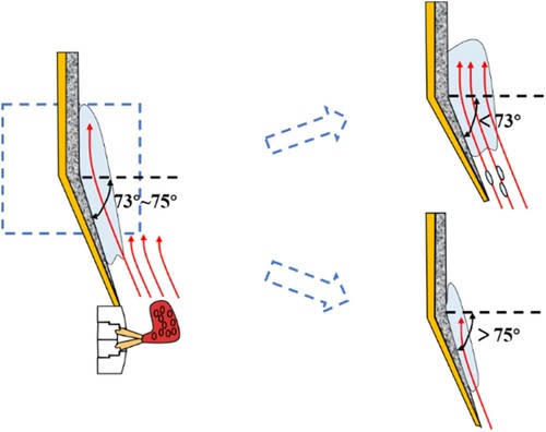
However, the direct wear effect of the burden on the cooling stave is relatively limited by reducing the bosh angle. If the edge gas is inhibited and the temperature at the front end of the cooling stave is low, slag crust will crystalize out. Slag crust effectively isolates the direct contact between the burden and the cooling stave and reduces the wear of the burden on the cooling stave. Therefore, it is one of the effective means to reduce the direct wear of the burden to the cooling stave by adjusting the thickness of the slag crust. The gas flow scouring curve is shown in . When the bosh angle is less than 73°, slag crust thickens continuously and the edge gas overdevelops, which causes slag crust melts and falls off. Rather the bosh angle is greater than 75°, the bearing of bosh, which is designed, the truncated cone is reduced, and slag crust is not easily hanged by the cooling stave.
Figure 8. Schematic diagram of the gas flow scouring curve.
The designed salamander depth in the world is shown in . The bosh angles in Germany, Korea, Brazil, and the Soviet Union are concentrated in 72.07°∼73.02°, 77.07°, 73.53°∼75.50° and 79.36°, respectively. Japanese blast furnace bosh angles are concentrated in 75.29° and 80.30°. The bosh angles of the blast furnace in China are relatively large, which are mainly about 77.82° and 81.34°.
Figure 9. The designed bosh angle in the world.

Comprehensively considering the comparative analysis of the actual bosh angle in the world and influence of bosh and the burden, gas, cooling stave and slag crust, it is necessary to reduce the designed bosh angle to 73°∼75° for low-carbon smelting and longevity in China. It is beneficial to stabilize the slag crust and reduce the wear of the burden to the cooling stave by lengthening the tuyere, which reduces equivalent bosh angle in actual production.
Conclusions
The physical and mathematical model of deadman and cooling stave of blast furnace is established, and the influence of blast furnace parameters on the reasonable salamander and bosh angle is theoretically analysed. At last, the designed salamander depth and bosh angle in the world are analysed. Some conclusions can be drawn as follows:
Based on the force model of the deadman and the cooling stave, the influence potential of the blast furnace production parameters on the salamander depth and bosh angle is analysed, which can provide certain guidance for the actual design and operation of the blast furnace in the future.
Based on the force model of the deadman of the blast furnace, it is found that the salamander depth of the blast furnace increases with the increase of the blast furnace volume. It is also specified that the core factor of the floating deadman is the voidage of the deadman. The salamander depth/hearth diameter ratio should be designed between 23 and 25% in China. In the production operation, the voidage of the deadman can be adjusted by controlling some parameters such as the coke ratio, wind speed and then the actual salamander depth can be adjusted. It is helpful to slow down the circulation erosion of molten iron.
Based on the force model of the blast furnace cooling stave, it is found that the interface of the belly and bosh is the point where the stress increases sharply and specified that the core factor of the cooling stave wear is the thickness of the slag crust. The bosh angle of thin-walled blast furnaces should be designed between 73° and 75°in China. In actual production operation, the equivalent bosh angle can be adjusted by controlling the length of the tuyere to adapt to the gas flow scouring curve. It ensures the stability of slag crust and reduces the friction of the cooling stave.
Acknowledgements
This work was financially supported by Important Projects in the Scientific Innovation of Shandong province (2019JZZY010404) and Young Elite Scientists Sponsorship Program CAST (2018QNRC001).
Disclosure statement
No potential conflict of interest was reported by the author(s).
Additional information
Funding
References
- Liu ZJ, Zhang JL, Zuo HB, et al. Recent progress on long service life design of Chinese blast furnace hearth. ISIJ Int. 2012;52:1713–1723.
- Wang YJ, Zuo HB, Zhao J. Recent progress and development of ironmaking in China as of 2019: an overview. Ironmak Steelmak. 2020;47:640.
- Wang ZY, Zhang JL, Liu ZJ, et al. Status, technological progress, and development directions of the ironmaking industry in China. Ironmak Steelmak. 2019;46:937.
- Dash SK, Jha DN, Ajmani SK, et al. Optimisation of taphole angle to minimise flow induced wall shear stress on the hearth. Ironmak Steelmak. 2013;31:207.
- Li YL, Cheng SS, Zhang P, et al. Sensitive influence of floating state of blast furnace deadman on molten iron flow and hearth erosion. ISIJ Int. 2015;55:2332.
- Zagaria M, Dimastromatteo V, Colla V. Monitoring erosion and skull profile in blast furnace hearth. Ironmak Steelmak. 2013;37:229.
- Esmer M, Özyiğit HA. a new approach for the wear failure risk of copper staves in blast furnaces. Trans Indian Inst Met. 2017;70:2137.
- Ghosh S, Viswanathan NN, Ballal NB. Flow Phenomena in the dripping zone of blast furnace − a review. Steel Res Int. 2017;88:1.
- Bi X, Qiu J, Wang W, et al. Influences of scaffold and coal injection on gas and liquid flow distributions in blast furnace: mathematical model. Ironmak Steelmak. 2013;28:27.
- Kuang SB, Li ZY, Yu AB. Review on modeling and simulation of blast furnace. Steel Res Int. 2018;89(1).
- Biao T, Ying ZZ, Hui Y, et al. The design for 3000 m3 blast furnace. Earth Environ Sci. 2018;199:1–4.
- Panjkovic V, Truelove JS, Zulli P. Numerical modelling of iron flow and heat transfer in blast furnace hearth. Ironmak Steelmak. 2013;29:390.
- Vångö M, Feilmayr C, Pirker S, et al. Data-assisted CFD modeling of transient blast furnace tapping with a dynamic deadman. Appl Math Model. 2019;73:210.
- Zhu HP, Zhou ZY, Yu AB. Stress fields of solid flow in a model blast furnace. Granular Matter. 2009;11:269.
- Zaïmi SA, Guillot JB, Biausser H. A solid flow model for blast furnace based on hypo-plasticity theory. Ironmak Steelmak. 2013;30:475.
- Zhang JL, Chen YX, Fan ZY, et al. Influence of profile of blast furnace on motion and stress of burden by 3D-DEM. J Iron Steel Res Int. 2011;18:1.
- Zhang HS, Guo YY, Chen C. Research on deadman state during tapping process. Ironmak Steelmak. 2017;45:678.
- Brännbacka J, Saxén H. Estimating the behavior of the liquid Levels and the Dead Man in the Blasting furnace hearth. New Technol Automat Metall Ind. 2003;36:53–58.
- Zhu JF, Zhao HB, chen SS, et al. Force analysis and calculation of deadman in a blast furnace hearth. J Univ Sci Techn Beijing. 2009;31:906, (in chinese).
- Cheng WT, Huang CN, Du SW. Three dimensional iron flow and heat transfer in the hearth of a blast furnace during tapping process. Chem Eng Sci. 2005;60:4485.
- Jiao KX, Zhang JL, Chen CL, et al. Analysis of the deadman features in hearth based on blast furnace dissection by comprehensive image-processing technique. ISIJ Int. 2019;59:16.
- Zhang L, Zhang JL, Jiao KX, et al. Observation of deadman samples in a dissected blast furnace hearth. ISIJ Int. 2019;59:1.
- Zhang L, Zhang JL, Zuo HB, et al. Temperature field distribution of a dissected blast furnace. ISIJ Int. 2019;59:1027.
- Chung KH, Wu JY, Yung CK. Experience of salamander tapping for blast furnace relining in CSC. China Steel Tech Rep. 2019;32:12.
- Fan XY, Jiao KX, Zhang JL, et al. Coke microstructure and graphitization across the hearth deadman regions in a commercial blast furnace. ISIJ Int. 2019;59:1770.
- Niu Q, Cheng SS, Xu WX, et al. Analysis of the coke particle size distribution and porosity of deadman based on blast furnace hearth dissection. ISIJ Int. 2019;59:1997.
- Agrawal A, Kor SC, Nandy U, et al. Real-time blast furnace hearth liquid level monitoring system. Ironmak Steelmak. 2016;43:550.
- Deng Y, Zhang JL, Jiao KX. Viscosity measurement and prediction model of molten iron. Ironmak Steelmak. 2018;45:773.
- Duarte RM, Ruiz-Bustinza I, Carrascal D, et al. Monitoring and control of hearth refractory wear to improve blast furnace operation. Ironmak Steelmak. 2013;40:350.
- Walker DM. An approximate theory for pressures and arching in hoppers. Chem Eng Sci. 1966;21:975.
- Walters JK. A theoretical analysis of stresses in silos with vertical walls. Chem Eng Sci. 1973;28:13.
- Takahashi H, Kawai H, Suzuki Y. Analysis of stress and buoyancy for solids flow in the lower part of a blast furnace. Chem Eng Sci. 2002;57:215.
- Xiang ZY. Study of long campaign life technology of blast furnace hearth in foreign countries. China Metallurgy. 2013;23(1). (in chinese).
- Tang H, Zou ZP, Xu J. Review on appropriate salamander depth of blast furnaces. J Iron Steel Res Int. 2013;25:1. (in chinese).
- Li KJ, Khanna R, Zhang JL, et al. The evolution of structural order, microstructure and mineral matter of metallurgical coke in a blast furnace: a review. Fuel. 2014;133:194.