
 ?Mathematical formulae have been encoded as MathML and are displayed in this HTML version using MathJax in order to improve their display. Uncheck the box to turn MathJax off. This feature requires Javascript. Click on a formula to zoom.
Abstract
Total ankle arthroplasty is the gold standard surgical treatment for severe ankle arthritis and fracture. However, revision surgeries due to the in vivo failure of the ankle implant are a serious concern. Extreme bone density loss due to bone remodelling is one of the main reasons for in situ implant loosening, with aseptic loosening of the talar component being one of the primary reasons for total ankle arthroplasty revisions. This study is aimed at determining the performance and potential causes of failure of the talar component. Herein, we investigated the stress, strain, and bone density changes that take place in the talus bone during the first 6 months of bone remodelling due to the total ankle arthroplasty procedure. Computed tomography scans were used to generate the 3D geometry used in the finite element (FE) model of the Intact and implanted ankle. The Scandinavian Total Ankle Replacement (STAR™) CAD files were generated, and virtual placement within bone models was done following surgical guidelines. The dorsiflexion physiological loading condition was investigated. The cortical region of the talus bone was found to demonstrate the highest values of stress (5.02 MPa). Next, the adaptive bone remodelling theory was used to predict bone density changes over the initial 6-month post-surgery. A significant change in bone density was observed in the talus bone due to bone remodelling. The observed quantitative changes in talus bone density over 6-month period underscore potential implications for implant stability and fracture susceptibility. These findings emphasise the importance of considering such biomechanical factors in ankle implant design and clinical management.
1. Introduction
Total ankle arthroplasty (TAA) is the gold standard surgical treatment for severe ankle arthritis and fractures. However, long-term performance is still a concern for TAA treatments. The aseptic loosening of tibial and talar components is the principal cause of TAA failure. A four-year follow-up study by Brunner et al. (2013) reported that 38% of TAA required revision surgery due to metallic component failure through loosening and infection [Citation1]. Furthermore, a 10-year follow-up study by Jastifier et al. (2015) found that 39% of TAAs required revision surgery due to loosening and infection [Citation2]. Stress/strain shielding is one of the primary mechanisms for tibial and talar component loosening. This stress/strain shielding causes excessive bone density loss due to pathological bone remodelling resulting in implant loosening [Citation3]. While there are a number of studies in the literature that investigate the failure performance of TAA, the majority of these have focused on the failure of the tibial component [Citation3–18]. However, there is a dearth of literature on the failure performance of the talar component, and the long-term failure performance of the talar component is not yet fully understood.
Bone remodelling is of significant importance for modelling the long-term performance of orthopaedic implants. The adaptive bone remodelling theory coupled with finite-element (FE) analysis has been used to predict implant-induced bone remodelling [Citation19]. The adaptive bone remodelling process describes the internal bone changes due to changes in bone density [Citation20,Citation21] and external changes due to the conversion of the outer shape of the bone [Citation22,Citation23]. Hitherto, the majority of studies on TAA performance have been limited to immediate post-operative boundary and loading conditions [Citation3–18]. Although, a recent study by Mondal and Ghosh (2019) investigated the bone remodelling in the tibia bone due to TAA [Citation24]. The bone density changes due to bone remodelling for first 6 months post-surgery in the tibia bone were predicted after the TAA procedure [24]. Bouguecha et al. (2011) [Citation25] and Rodrigues, (2013) [Citation26] also investigated bone remodelling following TAA with a particular focus on both the tibia and talus bone. However, there is a scarcity in most of the FE models of the intact and implanted ankle in terms of appropriate bone material modelling [Citation26], appropriate muscle force and ligamental boundary conditions [Citation25], and proper implant-bone interface conditions [Citation26]. Currently, there are no reported studies that have investigated bone remodelling in the talus with appropriate musculoskeletal loading conditions, suitable material modelling of the ankle joint, and accurate implant-bone interface conditions. Therefore, the present study focused on performance and potential causes of failure of talar components by means of predicting the load transfer and bone density distribution in the talus bone following TAA.
2. Materials and methods
2.1. Finite-element development of intact and implanted ankle
A computed tomography (CT) dataset was used for the development of the ankle joint. The CT data (512 × 512 pixels, pixel size of 0.803 mm and slice thickness of 1 mm) [Citation17,Citation18] of a 35-year-old female in digital imaging and communications in medicine (DICOM) format was imported into the MIMICS v 11.1 software (Materialise, Leuven, Belgium) for the development of the ankle joint model [Citation17,Citation18]. Manual thresholding was performed in MIMICS to separate the cortical and cancellous layers from each bone to correct the partial volume effect [Citation27–30]. The separation of cortical and cancellous bone depends on the threshold bone density of 1.3 g. [Citation27]. The higher value of threshold bone density, that is, 1.3 g.
, was considered to be cortical bone. The threshold Hounsfield unit (HU) was calculated using the threshold bone density of 1.3 g.
. The HU was determined to be 2,020 for the CT scan data used here. After the development of the bones around the ankle joint, the cartilage geometries between the junctions of the bones for the intact ankle joint FE model were developed. This was achieved by extruding a layer of constant thickness from each bone surface and using the Boolean operation to develop a continuous cartilage-bone interface. Generation of each cartilage geometry was performed manually in MIMICS 11.1. ANSYS 20.0 (ANSYS, Inc., PA, USA) was subsequently used to simulate the stress and strain distributions in the ankle joint following TAA under physiological loading conditions.
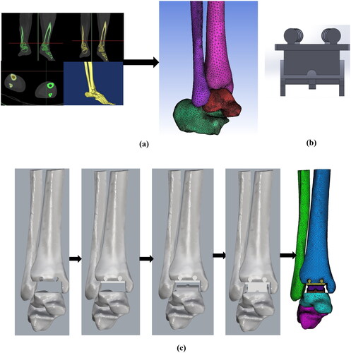
The modern three-component ankle prosthesis, Scandinavian Total Ankle Replacement (STAR™, Waldemar Link, Hamburg, Germany) was used here. The CAD file of the tibial, talar and meniscal bearing system of STAR™ was generated using SolidWorks software (DS Solidworks Corp., MA, USA). The size and dimensions of all three components of S.T.A.R@TM from earlier studies were used [Citation24,Citation30]. The virtual positioning and operation of prosthetic components with the bones were performed using Rhinoceros software v 7.0 (Robert McNeel & Associates, WA, USA) according to surgical guidelines (Small Bone Innovations, Inc.) [Citation24]. The bony landmarks and references were used according to the surgical guidelines to position the tibial component, talar component and meniscal bearing in Rhinoceros software. ANSYS (ANSYS, Inc., PA, USA) was used for the assignment of material properties, meshing, boundary and loading condition definition, and analysis. The development of 3D Model of all the bones from CT scan data, CAD model of the ankle prosthesis, and virtual operation, implant positioning of the prosthetic ankle joint is shown in .
Figure 1. (a) Development of 3D Model of all the bones from CT scan data, (b) CAD model of the ankle prosthesis, (c) Virtual operation, implant positioning of the prosthetic ankle joint.
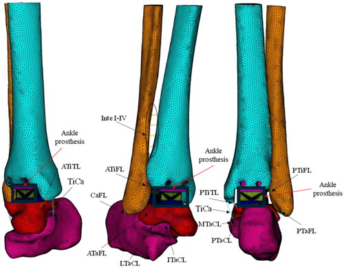
Ligaments were also modelled in ANSYS (ANSYS, Inc., PA, USA) using four parallel linear spring elements. A total of sixteen ligaments were implemented in the ankle joint (). The ligaments implemented in the model include Interosseous I–IV (Inte I–IV); Anterior tibiofibular (ATiFL); Posterior tibiofibular (PTiFL); Calcaneofibular (CaFL); Tibiocalcaneal (TiCa); Anterior talofibular (ATaFL); Posterior talofibular (PTaFL); Anterior tibiotalar (ATiTL); Posterior tibiotalar (PTiTL); Interosseoustalocalcaneal (ITaCL); Lateral talocalcaneal (LTaCL); Medial talocalcaneal (MTaCL); and Posterior talocalcaneal (PTaCL). The location and insertion points of the ligaments were taken from the literature [Citation24,Citation29,Citation30].
Figure 2. FE model of implanted ankle joint shows different ligamental boundary conditions.
2.2. Material properties
The cortical bone was modelled as a homogenous linear elastic material with a Young’s modulus (E) and Poisson’s ratio of 19 GPa and 0.3, respectively [Citation24,Citation30]. Cancellous bone was modelled as a heterogeneous linear elastic material with its properties derived from CT scan grey values. The CT grey value was used to determine the density and corresponding Young’s modulus for each element in the cancellous bone. The relationship was used to determine the Young’s modulus of cancellous bone where water was considered to have HU = zero, corresponding to the bone density of 0.022 g.
[Citation24,Citation30]. Whereas the highest HU value of 2,020 was considered to be cortical bone with a resulting bone density of 1.7 g.
. The Young’s modulus and Poisson’s ratio of tibial, talar and meniscal bearing were taken from the literature () [Citation24,Citation30]. The Young’s modulus and Poisson’s ratio of each ligament and cartilage component are also shown in [Citation26,Citation29–34].
Table 1. Material properties of bones, cartilage, ligaments and prosthetic components [Citation24, Citation26, Citation29–34].
2.3. Contact conditions
A fully bonded (osseointegrated) implant-bone interface condition was assumed for the FE model of the implanted ankle joint. Contact between the tibial component and meniscal bearing system, and the talar component and meniscal bearing system was assumed to be frictional [Citation24,Citation30], and an augmented contact algorithm was implemented in this analysis [Citation24,Citation30].
2.4. Boundary and loading conditions
The reaction forces for the dorsiflexion position of the ankle during normal walking were considered in the present analysis. The magnitude of the axial force (Z-component) was 1,600 N, the interior–exterior force (X-component) was −185 N, the anterior-posterior force (Y- component) was −185 N, and the interior-exterior torque (X-component) was −6.2 N-m [Citation26,Citation35] (). The Achilles tendon force was assigned at the posterior position of the calcaneus bone and the corresponding magnitude was 75% of the body weight. All the reaction forces were applied as per our global FE coordinate system. Fixed boundary conditions were applied to the proximal end of the tibia and fibula bones similar to previous studies in the literature [Citation24].
Table 2. Magnitude of reaction forces corresponding to dorsiflexion positions of ankle as per the present coordinate system [Citation24, Citation26, Citation30, Citation35].
2.5. The adaptive theory of bone remodelling
TAA leads to changes in the mechanical environment of the bone, which interrupts the normal state of equilibrium in a natural bone. Post-implantation, the implant carries the majority of the load, which was previously carried by the natural bone prior to the implantation [Citation19,Citation24,Citation36,Citation37]. Bone attempts to reach a new equilibrium state by adapting its structure internally and externally after implantation [Citation36,Citation37]. The adaptive process of changes in bone structure is called adaptive bone remodelling. The adaptive bone remodelling theory was used to assess the likelihood of loosening of the implant due to excessive bone density loss. The details of adaptive bone remodelling are described in this section.
The adaptive bone remodelling theory is based on strain energy density (SED) and site-specific bone [Citation36]. Changes in bone density occur more rapidly in cancellous bone than the changes in the external geometry of cortical bone, due to cancellous bone’s higher rate of metabolic activity [Citation37]. Bone undergoes significant density changes due to changes in the mechanical environment or stimulus. The elastic strain energy per unit of bone mass was considered as a stimulus in the bone remodelling algorithm. The reference and actual stimuli are the local elastic strain energy per unit bone mass averaged over a loading history, for an intact and implanted bone, respectively, given by the following:
(1)
(1)
Here, U represents the strain energy and S represents SED per unit bone mass averaged over a loading history (n = 1) for intact and periprosthetic talus bone. The extent of bone remodelling depends on the difference between the reference and remodelling stimuli and the dead zone. The dead zone or lazy zone (s) is the region in which bone is unresponsive in nature. For the dead zone (s), reference stimulus was taken as ± 0.75 [Citation19]. Here, represents the reference stimulus and
represents the remodelling stimulus. The rate of change of bone mass for the adaptive process in the operated bone is expressed as:
(2)
(3)
(3)
(4)
(4)
0.01≤≤1.73
where represents the free surface at the internal bone surface, and
is a time constant. The amount of alteration of bone mass
is expressed as an amount of variation in the internal bone mass owing to the porosity change:
(5)
(5)
where V represents the volume of the element, and the rate of change of apparent density is represented as . The mathematical expression for apparent bone density changes was similar to the earlier study by Mondal and Ghosh, (2019) [Citation24].
The change in apparent density in mathematically expressed as follows [Citation19,Citation24,Citation36]:
(6)
(6)
Euler’s forward integration can be used to solve this above EquationEquation (6)(6)
(6) to produce a new value of apparent density for all bone element after each iteration. Therefore, apparent density in each element and chosen time step Δt can be calculated by using the following equations:
(7)
(7)
Simulation time scale Δt was used for each integration procedure [36]. This time step
Δt was calculated by the following equation:
(8)
(8)
The iterative bone remodelling algorithm was based on earlier investigations [Citation19]. The integration was completed in steps on a simulation time scale [Citation19,Citation24]. The adaption rate, τ, was assumed as 129.6 g. months for calculating the simulation time scale [Citation19,Citation24].
2.1.1. Mesh sensitivity and postprocessing approach
In order to verify that the model is independent of element size, a mesh convergence study was conducted. There were four meshes created, with varying element lengths and sizes. Based on the von Mises stress distribution in the bone surrounding the ankle joint, a sensitivity investigation was carried out. The elements in the four meshes were as follows: Mesh 1 had 385,867 elements, Mesh 2 had 587,921 elements, Mesh 3 had 723,430 elements, and Mesh 4 had 967,822 elements. Until the variation in the von Mises stress distribution between meshes was less than 1%, the number of mesh elements was increased. The variation of equivalent stresses in the range of 0.1–1% was significantly reduced between Mesh 3 and Mesh 4. As such, Mesh 3, with its 723,430 elements (maximum edge length of 3 mm), was adequate for precise computational modelling.
The talus bone was divided into three regions of interest (ROI) for better presentation and visualisation of the results using ANSYS 20.0 (ANSYS, Inc., PA, USA). First, von Mises stress and strain distribution were investigated at the different ROIs of the talus bone after immediate post-operative condition. ANSYS 20.0 (ANSYS, Inc., PA, USA) postprocessing was used for contour plot of the talus bone. After the bone remodelling simulation, the density plot was extracted from ANSYS 20.0 (ANSYS, Inc., PA, USA) software using manual coding. Similar to the stress-strain distribution the talus bone was divided into the three ROIs for bone density distribution plot.
3. Results
3.1. Stress–strain distribution
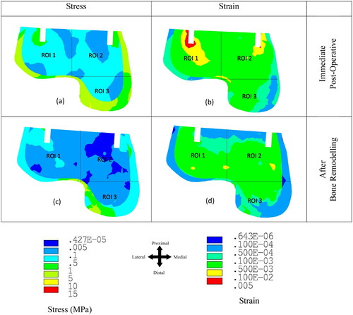
The dorsiflexion loading condition showed higher stress and strain values in the ankle joint compared to the neutral and plantarflexion loading during the stance phase of gait as shown in the previous literature [Citation24,Citation26,Citation30,Citation35]. Therefore, only the dorsiflexion loading condition was considered in the FE model. shows the equivalent stress and strain distributions at the talus bone (a) immediately post-implantation and (b) after 6 months of bone remodelling. The majority of the load was transferred through the outer cortex of the bone. The maximum value of von Mises stress in the outer cortex of the talus bone was found to be 5.02 MPa. Whereas the stress value was highest near the implantation area (ROI 1) in the talus cancellous bone compared to ROI 2 and ROI 3 immediately post-implantation (). The reduction in stress was observed over the 6 months in the talus bone. Stress shielding was observed in ROI 1–3 due to bone remodelling. Similarly, the strain value was observed to be highest in the region of the implant (ROI 1 and ROI 2) immediately post-surgical implantation (). Whereas ROI 1 showed a higher strain distribution (0.0047) compared to ROI 2 and ROI 3 (). Similarly, to the stress distribution, a reduction in the strain distribution was observed in ROI 1-3 after 6 months of equilibrium in bone remodelling (). The maximum reduction in strain was observed in ROI 1 and ROI 2.
Figure 3. von Mises stress and strain distribution at the talus bone after the immediate post-operative and bone remodelling condition.
3.2. Bone density distribution
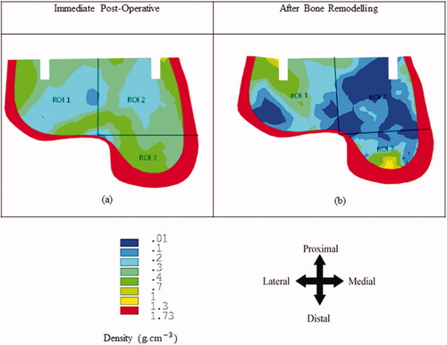
The bone remodelling study predicts bone density changes in the bone over the post-surgical implantation timeframe of 6 months. shows the bone density distribution in the talus bone before and after bone remodelling. Here, the bone density changes only within the cancellous bone due to its higher rate of metabolic activity compared to the cortical bone. represents the density distribution in the talus bone immediately post-surgical implantation. Whereas represents the bone density distribution in the talus after bone remodelling. Bone density reduction was observed in ROI 1–3 after the bone remodelling. ROI 2 showed the greatest reduction in average bone density at 7.23% compared with ROI 1 (5.18%) and ROI 3 (2.47%) ().
Figure 4. Bone density distribution at the talus bone after the immediate post-operative and bone remodelling condition.
4. Discussion
Ankle replacement surgery is becoming an increasingly popular treatment choice for ankle arthritis and fracture [Citation38,Citation39]. Clinical feedback has stated the performance of TAA has advanced in the last two decades due to the development of new designs of TAA prostheses [Citation39,Citation40]. However, long-term outcomes of TAA are still lacking in performance, similar to hip and knee replacement. Aseptic loosening is one of the primary causes for the failure of TAA. Post-operative biological factors including infection, osteolysis, progressive osteoporosis, avascular necrosis, periprosthetic fracture, and tumour formation can also contribute to the failure of TAA [Citation41]. One of the leading causes of TAA having suboptimal clinical outcomes is aseptic loosening of the talar component [Citation1,Citation42,Citation43]. Excessive bone density loss due to bone remodelling, high implant-bone micromotion at the interface, and wear-induced osteolysis can lead to talar component loosening [Citation17,Citation18,Citation30,Citation44–47]. The present study focused on the performance and failure analysis of the talar implant due to TAA. The aim of this study was to develop a realistic 3D FE model of the intact and implanted ankle joint and investigate the stress-strain distributions, and changes in the bone density distribution in the talus bone and talar component-bone interface failure due to TAA. The present FE model was validated using previously reported studies using the same material property, boundary and loading conditions [Citation8]. Direct one-to-one experimental validation of this ankle FE model was not possible, since the CT-scan data was based on a living subject. The predictions of this subject-specific FE model, however, have been qualitatively validated by comparing the FE predicted stress with those earlier published data [Citation8]. This indirect FE validation was carried out with similar loading and boundary condition was recreated [Citation8], the quantitative deviations in results are mainly attributed to the differences in geometry. After validation of the ankle FE model, further study was carried out to understand the stress, strain, and bone density changes due to bone remodelling in the talus bone following total ankle arthroplasty.
As failure is commonly defined in terms of stress or strain, a particular focus was given to the stress and strain distributions in the talus bone due to TAA. Our results suggest that there is stress shielding effect in the talus bone during the initial remodelling period (i.e. 6 months). Reductions in the stress and strain distributions were observed in the talus bone due to bone remodelling (). It has been indicated earlier that excessive stress or strain shielding in the bone causes resorption due to bone remodelling resulting in implant loosening [Citation24,Citation28,Citation40]. To identify quantitative changes in bone density, a bone remodelling simulation was performed in this study [Citation28,Citation30]. Bone remodelling simulations are very important to understand the bone density changes over time. Our results have shown that TAA resulted in a decrease in bone density in the talus due to bone remodelling. The maximum reduction in bone density was observed near the implantation area (ROI 2) (). Previously, it has been indicated that excessive bone density reduction over a period is one of the primary causes of implant loosening [Citation24,Citation28,Citation30].
Numerical assessments on ankle implant design, using FE analysis and simplified loading conditions, have often been valuable in gaining insight into deviations in load transfer and its relationship with failure mechanisms of the talar component [Citation40,Citation45]. Stress and strain distributions before and after the implantation showed an initial indication of bone density changes due to bone remodelling and subsequent failure [Citation28,Citation36,Citation40]. A major finding of the present study was demonstrating the high bone density reduction in the talus bone leading to the loosening of the talar component. These results were comparable to clinical findings of talar component aseptic loosening [Citation48,Citation49]. However, considering everyday activities alongside an adequate number of load cases for each activity is needed to predict clinically relevant outcomes on bone remodelling. The aseptic loosening and design of the talar component are one of the major reasons for TAA failure [Citation50]. The present study focused on understanding the potential failure mechanisms of the talar component. This study is important for understanding the complexity of the talus bone anatomy further it might contribute key aspects of the improvement of talar component design.
The FE model has some limitations and assumptions that should be noted. The present FE models only consider ligaments and cartilage but not fat, muscle or skin tissues. However, these are assumed to have a negligible impact on the biomechanics of the bone and implant due to the differences in their material properties [Citation29,Citation30]. Cancellous bone modulus–density relationships of talus bone were used the same as tibia bone. Ligaments were modelled as linear spring elements similar to an earlier study [Citation29]. Bone remodelling is known to be dependent on loading conditions; our study is limited to static loads (dorsiflexion) during the posturing stage of gait. Dynamic analysis of the ankle joint during a gait cycle may provide further insights into the load transfer between the bone and implant. A single CT scan was used for the development of the 3D bone geometry. A CT-averaged template of the ankle joint may provide a more comprehensive biomechanical response of the ankle joint following TAA compared to our patient-specific model. However, a qualitative estimation of results can still be predicted using single CT-scan models [Citation40]. The robustness and applicability of our conclusions would be improved by addressing the implications of our findings on various anatomies and patient profiles and by taking into account potential variations in simulation parameters. The bone remodelling model is constrained to cancellous bone. In the case of bone remodelling, the changes in internal remodelling are higher as compared to external remodelling [Citation20,Citation21]. However, both the remodelling (i.e. internal and external) occurs simultaneously [Citation23]. The changes in bone density occur more rapidly at the cancellous bone due to its higher rate of metabolic activity than the changes in the external geometry of cortical bone [Citation37]. The majority of studies focusing on bone remodelling based on this internal remodelling of cancellous bone [Citation19,Citation20,Citation24,Citation36,Citation51–54].
4.1. Clinical relevance
This study contributes to the understanding of the biomechanics and bone remodelling processes in the talus bone following TAA. The results of this investigation have important clinical implications for TAA and could lead to better surgical results, fewer revision procedures, and longer-lasting ankle implants. The investigation into stress, strain, and bone density changes in the talus bone, particularly the talar component, provides valuable insights into potential causes of in vivo failure and implant loosening following TAA. Understanding these biomechanical aspects is pivotal for refining implant design and surgical techniques to mitigate the risk of aseptic loosening, a primary factor necessitating TAA revisions [Citation40]. Moreover, the study’s focus on the initial 6 months of bone remodelling post-surgery is clinically relevant, as this period is integral for predicting long-term outcomes and guiding postoperative care strategies. By utilising CT scans and FE modelling, the research contributes to a comprehensive understanding of the performance and potential failure mechanisms of the talar component in TAA, thereby informing clinical practices to enhance the longevity and success of ankle arthroplasty procedures [Citation40].
5. Conclusions
Here, an appropriate and validated 3D FE model of the implanted ankle joint was developed based on CT scan data including regional material property distributions, ligaments, and anatomically appropriate boundary and loading conditions. The results demonstrated that the majority of the load was transferred through the talus cortical bone compared to the cancellous bone. Stress shielding in the talus bone caused a decrease in bone density and subsequently poor bone quality. The bone remodelling results presented a clear indication of quantitative bone density changes in the talus bone following 6 months of bone remodelling equilibrium. It is postulated that an excessive reduction in talus bone density could play a significant role in loosening and fracture of the implant’s talar component.
Author contributions
Subrata Mondal: Conceptualisation, Visualisation, Formal analysis, Investigation, Methodology, Software, Validation, Writing-Original Draft. David B MacManus: Formal analysis, Conceptualisation, Visualisation, Investigation, Resources, Supervision, Writing-Review & Editing. Rajesh Ghosh: Methodology, Conceptualisation, Visualisation, Investigation, Resources, Supervision, Writing-Review & Editing. Abhishek Banagunde: Methodology, Software, Validation, Writing-Original Draft. Nicholas Dunne: Conceptualisation, Visualisation, Investigation, Resources, Supervision, Writing-Review & Editing. All authors discussed the results and suggestions and mentioned on the manuscript at all steps. All authors have approved the final article.
Ethical approval
The authors hereby declare that proper approval has been obtained from the patient for the submission of this research publication in accordance with institutional rules and procedures. Informed consent was given by the patient receiving treatment for the collection and use of CT data for study.
Disclosure statement
No potential conflict of interest was reported by the author(s).
Data availability
The authors will provide the raw data used to support the results in this article upon reasonable request.
Additional information
Funding
References
- Brunner S, Barg A, Knupp M, et al. The Scandinavian total ankle replacement long-term, eleven to Fifteen-Year, survivorship analysis of the prosthesis in seventy-two consecutive patients. J Bone & Joint Sur. 2013;95(8):711–718.
- Jastifer JR, Coughlin MJ. Long-term follow-up of mobile bearing total ankle arthroplasty in the United States. Foot Ankle Int. 2015;36(2):143–150. doi: 10.1177/1071100714550654.
- Elliot JB, Gundapaneni D, Goswami T, et al. Finite element analysis of stress and wear characterization in total ankle replacements. J Mech Behv Biomed Mat. 2014;34:134–145.
- Espinosa N, Walti M, Favre P, et al. Misalignment of total ankle components can induce high joint contact pressures. J Bone Joint Surg. 2010;92:1179–1187.
- Gundapaneni D, Tsatalis TJ, Laughlin TR, et al. Wear characteristics of WSU total ankle replacement devices under shear and torsion loads. J Mech Behv Biomed Mat. 2015;44:202–223.
- Martinelli N, Baretta1 S, Pagano J, et al. Contact stresses, pressure and area in a fixed bearing total ankle replacement: a finite element analysis. BMC Musc Dis. 2017;18:493.
- Miller CM, Smolinski P, Conti S, et al. Stresses in polyethylene lines in a semi constrained ankle prosthesis. J Biomech Engg. 2004;126(5):636–40.
- Ozen M, Sayman O, Havitcioglu H, et al. Modelling and stress analyses of a normal foot-ankle and a prosthetic foot-ankle complex. Acta Bio & Biomech. 2013;15(3):19–27.
- Putra AMS, Harun MN, Kadir MRA, et al. Polyethylene wear in total ankle replacement is influenced by its radial curvature: a computational wear simulation study. International Medical Device and Technology Conference 2017.
- Putra SMA, Harun NM, Ardiyanshyah S, et al. Study of wear prediction on total ankle replacement. Adv Mat Res. 2014;845:311–315.
- Reggiani B, Leardini A, Corazza F, et al. Finite element analysis of a total ankle replacement during the stance phase of gait. J Biomech. 2006;39:1435–1443.
- Sopher SR, Andrew AA, James DC, et al. Total ankle replacement design and positioning affect implant-bone micromotion and bone strains. Med Eng Phys. 2017;42:80–90.
- Terrier A, Fernandes CS, Guillemin M, et al. Fixed and mobile bearing total ankle prostheses: effect on tibial bone strain. Clin Biomech. 2017;48:57–62.
- Terrier A, Larrea X, Guerdat J, et al. Development and experimental validation of a finite element model of total ankle replacement. J Biomech. 2014;47:742–745.
- Wang YLZ, Wong DWC, Cheng CK, et al. Finite element analysis of biomechanical effects of total ankle arthroplasty on the foot. J Ortho Trans. 2018;12:55–65.
- Wei F, Hunley SC, Powell JW, et al. Development and validation of a computational model to study the effect of foot constraint on ankle injury due to the external rotation. Annals of Biomech Engg. 2011;39:756–765.
- Mondal S, Ghosh R. The effects of implant orientations and implant–bone interfacial conditions on potential causes of failure of tibial component due to total ankle replacement. Journal of Med and Bio Engg. 2019;39:541–551.
- Mondal S, Ghosh R. Effects of implant orientation and implant material on tibia bone strain, implant-bone micromotion, contact pressure, and wear depth due to total ankle replacement. Proc IMechE Part H: j Eng in Med. 2019;233(3):318–331.
- Ghosh R, Gupta S. Bone remodelling around cementless composite acetabular components: the effects of implant geometry and implant-bone interfacial conditions. J Mech Behavior Biomed Mat. 2014;32:257–269.
- Huiskes R, Weinans H, Grootenboer HJ, et al. Adaptive bone-remodelling theory applied to prosthetic-design analysis. J Biomech. 1987;20:1135–1150.
- Carter D, Orr TE, Fyhrie D. Relationships between bone loading history and femoral cancellous bone architecture. J Biomech. 1989;22(3):231–244. doi: 10.1016/0021-9290(89)90091-2.
- Hart RT, Davy DT, Heiple KG. Mathematical modelling and numerical solutions for functionally dependent bone. Calc Tissue Int. 1984;36:11–18.
- Hart RT, Davy DT. Theories of bone modelling and remodelling, in bone mechanics. (Ed Cowin SC) Boca Reton, FL, CRC Press 1989; 449–454.
- Mondal S, Ghosh R. Bone remodelling around the tibia due to total ankle replacement: effects of implant material and implant–bone interfacial conditions. Comp Met in Biomech and Biomed Engg. 2019;22:1247–1257.
- Bouguecha A, Weigel N, Behrens BA, et al. Numerical simulation of strain-adaptive bone remodelling in the ankle joint. Biomed Engg Online. 2011;10(58):2–13.
- Rodrigues DSOS. Biomechanics of the total ankle arthroplasty: Stress analysis and bone remodelling [master of science thesis]. Tecnico Lisboa, Portugal; 2013.
- Varghese B, Short D, Penmetsa R, et al. Computed-tomography-based finite-element models of long bones can accurately capture strain response to bending and torsion. J Biomech. 2011;44:1374–1379.
- Ghosh R, Mukharjee K, Gupta S. Bone remodelling around uncemented metallic and ceramic acetabular components. Proc IMechE Part H: J Eng in Med. 2013;227(5):490–502.
- Mondal S, Ghosh R. A numerical study on stress distribution across the ankle joint: effects of material distribution of bone, muscle force and ligaments. J Ortho. 2017;14:229–235.
- Mondal S, Ghosh R. Influence of cancellous bone material and dead zone on stress-strain, bone stimulus and bone remodelling around the tibia for total ankle replacement. Proc IMechE Part H: J Eng in Med. 2021;235:185–196.
- Beumar A, Hemert WLV, Swierstra BA, et al. A biomechanical evaluation of the tibiofibular and tibiotalar ligaments of the ankle. Foot Ankle Inter. 2003;24:426–429.
- Corazza F, O'Connor JJ, Leardini A, et al. Ligament fibre recruitment and forces for the anterior drawer test at the human ankle joint. J Biomech. 2003;36(3):363–372.
- Bekero VDMP, Raven EE. The distal fascicle of the anterior inferior tibiofibular ligament as a cause of tibiotalar impingement syndrome: a current concepts review. Knee Surg Sports Traumatol Arthro. 2007;15(4):465–471.
- Liacouras PC, Wayne JS. Computational modelling to predict mechanical function of joints: application to the lower leg simulation of two cadaver studies. J Biomech Eng. 2007;129(6):811–817. doi:10.1115/1.2800763.
- Procter P, Paul JP. Ankle joint biomechanics. J Biomech. 1982;15(9):627–634. doi:10.1016/0021-9290(82)90017-3.
- Weinans H, Huiskes R, van Rietbergen B, et al. Adaptive bone remodelling around bonded noncemented total hip arthroplasty: a comparison between animal experiments and computer simulation. J Orthop Res. 1993;11(4):500–513.
- García JM, Doblaré M, Cegonino. Bone remodelling simulation: a tool for implant design. Comput Mater Sci. 2002;25:100–114.
- Talbott H, Jha S, Gulati A, et al. Clinically useful finite element models of the natural ankle – a review. Clin Biomech. 2023;106:106006.
- Pappas MJ, Buechel FF. Failure modes of current total ankle replacement systems. Clin Podiatr Med Surg. 2013;30(2):123–143. doi: 10.1016/j.cpm.2012.10.002.
- Mondal S, Ghosh R. Experimental and finite element investigation of total ankle replacement: a review of literature and recommendations. J Ortho. 2020;18:41–49.
- Goodman SB, Gallo J. Periprosthetic osteolysis: mechanisms, prevention and treatment. J Clin Med. 2019;8(12):2091. doi: 10.3390/jcm8122091.
- Angthong C, Chumchuen S, Khadsongkram A. A systematic review of intermediate-term outcomes and failure rates for total ankle replacements: an asian perspective. Foot Ankle Surg. 2013;19(3):148–154. doi: 10.1016/j.fas.2013.04.005.
- Spirt AA, Assal M, Hansen ST.Jr Complications and failure after total ankle arthroplasty. J Bone Joint Surg. 2004;86(6):1172–1178.
- Mondal S, Ghosh R, Jyoti. Biomechanical analysis of three popular tibial designs for TAR with different implant-bone interfacial conditions and bone qualities: a finite element study. Med Eng Phys. 2022;104:103812.
- Yu J, Zhang C, Chen WM, et al. Finite-element analysis of the influence of tibial implant fixation design of total ankle replacement on bone–implant interfacial biomechanical performance. J Orthop Surg. 2020;28(3):2309499020966125.
- Quevedo González FJ, Steineman BD, Sturnick DR, et al. Biomechanical evaluation of total ankle arthroplasty. Part II: influence of loading and fixation design on tibial bone-implant interaction. J Orthop Res. 2021;39(1):103–111.
- Moideen ISM, Lim CT, Yeow RCH, et al. Finite element analysis of bone-prosthesis interface micromotion for cementless talar component fixation through critical loading conditions. Int J Numer Method Biomed Eng. 2020;36(3):e3310.
- Kotnis R, Pasapula C, Anwar F, et al. The management of failed ankle replacement. J Bone Joint Surg Br. 2006;88-B(8):1039–1047.
- Bolton-Maggs BG, Sudlow RA, Freeman MA. Total ankle arthroplasty. A long-term review of the london hospital experience. J Bone Jt Surg. 1985;67-B(5):785.
- Mohd MIS, Lim CT, Yeow RCH, et al. Polka dot cementless talar component in enhancing total ankle replacement fixation: a parametric study using the finite element analysis approach. Comput Biol Med. 2022;141:105142.
- McNamara BP, Taylor D, Prendergast PJ. Computer prediction of adaptive bone remodelling around noncemented femoral prostheses: the relationship between damage-based and strain-based algorithms. Med Eng Phys. 1997;19(5):454–463. doi: 10.1016/s1350-4533(97)00002-7.
- Behrens BA, Nolte I, Wefstaedt P, et al. Numerical investigations on the strain-adaptive bone remodelling in the periprosthetic femur: influence of the boundary conditions. Biomed Eng Online. 2009;8(1):7. doi: 10.1186/1475-925X-8-7.
- Beaupré GS, Orr TE, Carter DR. An approach for time-dependent bone modelling and remodelling-application: a preliminary remodelling simulation. J Orthop Res. 1990;8(5):662–670. doi: 10.1002/jor.1100080507.
- Fridez P, Terrier A, Rakotomanana L, et al. Three-|dimensional model of bone external adaptation. Comput Methd Biomech Biomed Eng. 1998;2:189–196.