Abstract
The classical Sommerfeld half-space problem is revisited, with generalizations to multilayer and plasmonic media and focus on the surface field computation. A new ab initio solution is presented for an arbitrarily oriented Hertzian dipole radiating in the presence of a material half-space with arbitrary horizontal stratification. The solution method combines the vector potential approach and the spectral domain transmission line analog of the medium, which results in the most compact formulation and facilitates the inclusion of any number of layers in the analysis. Following Sommerfeld, the solution is first expressed in terms of the Fourier–Bessel transforms, also known as Sommerfeld integrals. Analytical properties of the integrands in the complex plane are then investigated, including the location of the Sommerfeld pole, which gives rise to the Zenneck wave (ZW) or surface plasmon polariton (SPP), and alternative field representations are developed by a deformation of the integration path and analytic continuation of the integrand functions, using hyperbolic and vertical branch cuts. Closed-form expressions for the asymptotic surface fields are also derived and the rôle of the ZW and SPP is elucidated. Numerical examples are included to illustrate the theory, from radio frequencies to visible light.
1. Introduction
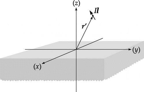
The problem of a vertical Hertzian dipole (time-harmonic current element of infinitesimal length) radiating in the presence of a lossy conducting half-space was first rigorously solved by Sommerfeld [Citation1] in 1909 and other dipole configurations were treated in his later works.[Citation2–Citation4]Footnote1 Sommerfeld originally placed the dipole in the interface between the two half-space media, but this caused some unnecessary mathematical difficulties,[Citation3,Citation6] hence most authors – including Sommerfeld in his later monograph [Citation4] – put it above the half-space, as indicated in Figure .
In his celebrated 1909 paper, Sommerfeld first expressed the solution in terms of improper integrals with Bessel function kernels – Fourier–Bessel transforms (FBTs) now known as Sommerfeld integrals, which cannot be evaluated in closed form. Sommerfeld then deformed the real-axis integration path into the complex plane, capturing two hyperbolic branch cuts, whose contribution he identified as space waves (Raumwellen), and a pole, whose residue he identified as a radial–cylindrical form of the plane surface wave of Zenneck [Citation7]. Sommerfeld further derived an asymptotic surface field expression, assuming high media contrast and large horizontal range. This formula consisted of a whole-space term multiplied by a factor – now known as the Sommerfeld attenuation function, which accounts for the influence of the ground through a complex parameter – the Sommerfeld numerical distance. Unfortunately, as it later turned out, this groundwave (Bodenwelle) expression was erroneous.Footnote2 Subsequently, as documented by Maclean and Wu [Citation10], several authors – among them Weyl [Citation11] and Sommerfeld in a paper under the same title as the original one [Citation2] – solved the problem by different methods and obtained the correct asymptotic surface field formula. A reprise of Sommerfeld’s 1926 solution was later given by Kockel [Citation12]. Inexplicably, the discovery of the sign error in Sommerfeld’s original paper unleashed a prolonged controversy in the literature as to its root cause – even though the correct solution was available since at least 1926.[Citation13,Citation14] Various explanations were put forward – all eventually debunked, and doubts were even cast on the very existence of the Sommerfeld pole and the associated ZW.Footnote3 From the modern perspective, it is rather surprising that such a relatively simple boundary value problem, which is capable of being solved completely with no room for debate, should have generated so much controversy – with some echoes of the past confusion reverberating to this day.[Citation20,Citation21] The groundwave formulation that eventually became the de facto standard is due to Norton [Citation22], who based it on an earlier work of van der Pol and Niessen [Citation23,Citation24]. This Norton surface wave,[Citation13] or Sommerfeld–Norton groundwave,[Citation25] [Citation10, p.97], [Citation26, p.310], which is applicable at any point in space not too near the antenna, was later derived by Wait [Citation27] using the modified saddle-point method, and by King [Citation28], and more recently by Green [Citation29], using the surface impedance concept and compensation theorem. Perhaps the most recent groundwave formulation is due to King [Citation30], who – eschewing the use of Hertz potentials and complex integral transforms – based it on the real-axis field representation.
Sommerfeld’s work was motivated by the desire to explain the radio wave propagation along the surface of the earth, before it was realized that reflections from the ionosphere were in fact the decisive factor. However, in recent years there has been a resurgence of interest in the Sommerfeld half-space problem and the Sommerfeld groundwave in particular, in the context of THz applications, near-field optics, plasmonics, and nanophotonics.[Citation31–Citation34] The ZW becomes a SPP in the case of noble metals at optical wavelengths.[Citation35–Citation37] An important extension of the Sommerfeld problem arises when the lower half-space comprises two or more layers. This case was first treated by Grosskopf using the Weyl formulation,[Citation38] and later by Wait [Citation39–Citation42], and more recently by King and Sandler [Citation43].Footnote4 At radio frequencies, the two-layer case can model the effect of a thin ice layer on top of the ground or body of water,[Citation43] while in the THz regime and plasmonics, it applies in case of a dielectric-coated metal [Citation45] or silver contaminated by a nanolayer of oxide tarnish.[Citation46] The multilayer geometry is relevant, for example, to the ground penetrating radar (GPR) modeling of water spillage from underground pipes.[Citation47]
The solution procedure employed by Sommerfeld may be classified as the method of scattering superposition,[Citation48] since it uses a Fourier–Bessel integral representation of the primary excitation – the Sommerfeld identity, as the point of departure. The reflected and transmitted fields are then expressed in compatible axial transmission representation [Citation49] forms and the total field integrands are matched at the interface, using the boundary conditions to determine the unknown amplitudes. Subsequently, the real-axis integrals may be analytically continued into the complex plane, taking into account any singularities captured in the path deformation process – in this case the branch points associated with the upper and lower half-spaces and the Sommerfeld pole. If the path is confined to the proper Riemann sheet, as in Sommerfeld’s original work, the radial transmission representation [Citation49] of the solution is obtained, comprising integrals around the hyperbolic branch cuts and the pole residue. However, there is a considerable leeway in the choice of branch cuts, and vertical cuts are often employed in surface wave studies, since the path around the branch point associated with the upper half-space then becomes the steepest descent path. The Sommerfeld pole contribution may, or may not, explicitly appear in this nonspectral representation,Footnote5 depending on the media parameters, but it always exists in the radial transmission representation (with the hyperbolic branch cuts), if there is some loss present in the lower half-space medium.
In the present paper, we revisit the Sommerfeld half-space problem and present a new, ab initio solution – dispensing with the method of scattering superposition – for the more general case of a lower half-space with arbitrary horizontal stratification. Our method combines the vector potential approach and the spectral domain transmission line (TL) network analog of the medium, which results in the most compact formulation and facilitates the inclusion of any number of layers in the analysis. The surface fields are first expressed as FBTs (or Sommerfeld integrals) of the appropriate combinations of the TL Green functions, resulting in the axial transmission representation. The analytical properties of these integrands in the complex plane are then investigated – including the location of the Sommerfeld pole, which gives rise to ZW or SPP, and alternative field representations – termed radial transmission and nonspectral – are developed by suitable deformations of the real-axis integration path around the singularities in the complex plane. Using the nonspectral representation as the point of departure, closed-form expressions of the asymptotic surface fields are derived and the rôle of the Zenneck and surface plasmon waves is discussed. Although from the mathematical standpoint the solution of this problem is identical whether at radio wavelengths or in the optical regime, there are some important nuances in the way these waves contribute to the surface field, and these nuances are elucidated. Further, certain misleading statements recently promulgated in the literature regarding the existence of the Sommerfeld pole and the associated ZW are pointed out. The theoretical developments are supported by numerous numerical examples – from the lossy ground at radio frequencies to plasmonic media in the visible range, including homogeneous and coated half-spaces excited by vertical and horizontal dipoles.
2. Formulation
2.1. Derivation of the Green dyadics – the general case
We begin with the Maxwell’s equations [Citation50]Footnote6(1)
for a medium with -dependent permeability
and permittivity
. Using the fact that
is divergenceless, we introduce the vector potential
and the scalar potential
as
(2)
to obtain(3)
where is the wavenumber of the medium. Since the number of unknowns in (Equation3
(3) ) exceeds by one the number of equations, an additional normalizing equation is needed. Upon inspecting the Cartesian components of (Equation3
(3) ), we note that the gage condition [Citation51]
(4)
results in great simplifications. Using this gauge in (Equation2(2) ), we find that the electric and magnetic fields may be computed from
alone as
(5)
Next, we use (Equation4(4) ) to eliminate
from (Equation3
(3) ) and obtain
(6)
(7)
(8)
where the subscript denotes vectors and operators transverse to
. It is apparent from these equations that unless the medium is homogeneous, a horizontal
- or
-directed current source requires not only the corresponding horizontal component of
, but also the vertical component,
. Further, these equations suggest that we introduce the Green functions
,
, and
asFootnote7
(9)
(10)
(11)
where is the Dirac delta function. We thus infer that for an arbitrary current distribution, occupying a volume
, the vector potential may be found as
(12)
where(13)
with . We have thus obtained the simplest possible form of the vector potential Green dyadic
, expressed in terms of three scalar functions, for the case of
-dependent media.[Citation51–Citation53] Note that the off-diagonal terms in (Equation13
(13) ) are absent only for a homogeneous space. For later convenience, we express (Equation13
(13) ) asFootnote8
(14)
Turning next to the task of solving (Equation9(9) )–(Equation11
(11) ), we first note that the equation for
involves
in the forcing function, which is cumbersome. To remedy this, we introduce an auxiliary Green function
by means of the relation
(15)
which upon using (Equation11(11) ) and (Equation9
(9) ) leads to
(16)
We will thus find indirectly from (Equation15
(15) ) by first solving (Equation9
(9) ) for
and (Equation16
(16) ) for
. We will also initially assume that the source point lies on the
-axis of the cylindrical coordinate system
, which results in a much simpler
-independent configuration, and subsequently generalize to the off-axis dipole case by the substitutions
and
, where
(17)
Hence, under this assumption, we may express (Equation9(9) ) as
(18)
where now(19)
Further, in view of the azimuthal symmetry, we may avail ourselves of the FBT pairFootnote9 [Citation55, p.21](20)
to simplify the solution. Hence, the application of the direct FBT has the effect(21)
and reduces (Equation18(18) ) to the Sturm–Liouville (SL) problem [Citation56, p.274]
(22)
subject to the requirement that [Citation57, p.176](23)
Similar treatment of (Equation10(10) ) yields another SL problem
(24)
subject to the requirement that(25)
Finally, applying this procedure to (Equation16(16) ), we obtain
(26)
subject to (Equation25(25) ), and the direct FBT of (Equation15
(15) ) yields
(27)
While (Equation22(22) )–(Equation26
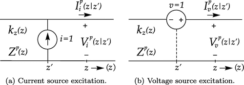
(26) ) may be solved by a conventional Green function procedure,[Citation57] herein we utilize the TL network method.[Citation49,Citation56,Citation58] The relevant network problems are illustrated in Figure (a) and (b), which depict TLs excited by ideal unit-strength current and voltage generators, respectively.
These TLs are characterized by -dependent propagation “constants”
and characteristic impedances
, where the superscript
can assume the values
(TM mode) or
(TE mode), given as [Citation56, p.190]
(28)
For the current source excitation, the voltage and current
obey the TL equations
(29)
where denotes the characteristic admittance, and we find that
satisfies the second-order differential equation
(30)
For the voltage source excitation, the voltage and current
obey the TL equations
(31)
and satisfies the second-order differential equation
(32)
The voltages and currents in Figure may be considered TL Green functions, since they are excited by unit-strength impulsive sources. The superscript on
or
indicates the TL type (
for TM line,
for TE line), and the subscript
or
indicates the source type (shunt current generator or series voltage generator, respectively). Note that the TM and TE lines have the same propagation constants, but differ in their characteristic impedances – see (Equation28
(28) ). The advantage of the network method is that the solution of any SL problem, such as (Equation22
(22) ) or (Equation24
(24) ), may be expressed in terms of a suitable TL Green function, by inspection of either (Equation30
(30) ) or (Equation32
(32) ). Since the behavior of TL voltages and currents is well understood, we thus also gain valuable insight as to the nature of the layered medium Green functions.
Applying the network method to (Equation22(22) ), we note the analogy with (Equation30
(30) ) in the TE case, where
, and a comparison of these equations immediately yields
(33)
Note that the continuity conditions (Equation23(23) ) are automatically satisfied, since the voltage and current are continuous outside the source. Similarly, comparison of (Equation24
(24) ) and (Equation32
(32) ) in the TM case, where
, yields
(34)
Turning attention to (Equation26(26) ), we note that it differs in form from the SL problems (Equation22
(22) ) and (Equation24
(24) ), as it comprises a more complicated driving function, involving a derivative of the Dirac delta. However, in this case, we use the analogy with the equation satisfied by
, which follows from (Equation29
(29) ):
(35)
In the TM case, this reduces to (Equation26(26) ), hence
. Finally, from (Equation27
(27) ) and (Equation33
(33) ) we obtain
(36)
We have thus expressed the three spectral domain Green functions required in (Equation13(13) ) in terms of the TL Green functions. We note that a vertical Hertzian dipole contributes a voltage source on a TM TL analog, whereas a horizontal dipole contributes current sources on both the TM and TE lines.
What remains is the simple step of the FBT inversion of the the spectral domain Green functions derived above. For later convenience, we first introduce the shortcut notation(37)
for the Sommerfeld integrals. Hence, on applying the inverse FBT to (Equation33(33) ) and (Equation34
(34) ), we arrive at
(38)
(39)
where we have also invoked (Equation17(17) ). Finally, the FBT inversion of (Equation36
(36) ) followed by differentiation with respect to
yieldsFootnote10
(40)
whereas differentiation with respect to yields
, with
in place of
.
We have thus formulated the Green dyadic in terms of the TL Green functions of the network analog of the medium along the
-axis. Since all TL Green functions can be obtained from
and
, we have in effect expressed all
components in terms of two scalar wave functions. Further, only three Sommerfeld integrals need to be computed to determine
in the most general case. Similar representations were previously obtained using different methods by Michalski [Citation53] and Michalski and Mosig [Citation59] – the latter including the uniaxial medium case. The approach presented here combines the direct vector-potential method of Dmitriev [Citation51] and the TL analog of the medium,[Citation56] thus resulting in a very compact, yet general, formulation.
Note that no assumptions have so far been made regarding the variation of and
or the source location, hence the formulation is applicable to arbitrary current distributions in media with arbitrary stratification perpendicular to the
-axis. In particular, the vector potential due to the Hertzian dipole of Figure may be found as
(41)
and the corresponding electric and magnetic fields then readily follow from (Equation5(5) ).
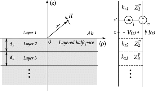
2.2. Dipole above a layered half-space with piecewise-constant parameters
Henceforth, we assume that the dipole resides in air above a layered half-space characterized by piecewise-constant and
, which in layer
assume the values
and
, respectively. The total number of layers (including the upper half-space) will be denoted by
. The corresponding TL network analog is illustrated in Figure , where the
th layer is represented by a TL section with propagation constant
and characteristic impedance
.
It will be recalled that in general two TL networks arise, with (TM mode) and
(TE mode). The relevant TL Green functions are readily found by a simple network analysis, as described in Appendix 1. Using these results in (Equation38
(38) )–(Equation40
(40) ), we may express the vector-potential Green functions in the upper half-space as
(42)
(43)
(44)
where and
is the reflection coefficient looking down from air into the lower half-space. In the above, we have expressed the direct (whole-space) terms in a closed form, using the Sommerfeld identity [Citation1]
(45)
The electric and magnetic fields for an arbitrarily oriented dipole above the half-space may now be computed via (Equation41(41) ) and (Equation5
(5) ). Henceforth, we assume a unit-strength dipole placed at
on the
-axis and limit attention to surface fields (
) in air when
h. It will suffice to only consider a vertical (
-oriented) and a horizontal (
-oriented) dipole. For the vertical dipole, we readily find the nonzero cylindrical components of the surface fields as
(46)
(47)
(48)
For the horizontal dipole, we similarly obtain(49)
(50)
(51)
(52)
(53)
(54)
Note that some of the expressions above are approximate, meaning that we have retained only the dominant terms, neglecting terms that decay more rapidly with . This is permissible, as we focus on the surface fields far from the dipole.
2.3. Integrand singularities and the Sommerfeld pole
The integrands in (Equation46(46) )–(Equation54
(54) ) comprise the propagation constants
, which are double valued with branch points at
, as discussed in Appendix 2. In the case of multilayer media, the integrands are even functions of
associated with all finite-thickness layers, hence
and
are the only branch points. To show this, we note that the change
only affects the reflection and transmission coefficients in sections
and
. If section
is finite, we find that under this sign change
turns into its inverse, but
and all reflection coefficients to the left of section
remain unchanged. The integrands in (Equation46
(46) )–(Equation54
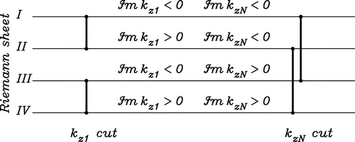
(54) ) may thus be viewed as defined on a four-sheeted Riemann surface, depicted schematically in Figure , where the vertical line segments represent the branch cuts and offer a passage between the sheets.[Citation17, p.56], [Citation60, p.613], [Citation61]. The radiation conditions are satisfied everywhere on sheet
, which will be referred to as the top or proper sheet.
Figure 4. Schematic diagram of the four-sheeted Riemann surface with fundamental branch cuts associated with and
.
In addition to the branch points, the spectral integrands have poles, which may be found from the transverse resonance condition [Citation62, Section 3.6](55)
Hence, the poles are roots of the denominator of the reflection coefficient (EquationA10(A10) ) looking from air into the layered half-space. The dispersion function
is also defined over the four-sheeted Riemann surface and can have roots on any of the sheets.[Citation63] However, only those located on the top sheet are proper and are termed surface wave poles; the ones on the other sheets are improper and are termed leaky wave poles. In the general case of a multilayer half-space, the poles can only be determined by a numerical search for the roots of the dispersion function (Equation55
(55) ) in the complex
-plane, as no closed-form formula is available. The most effective root location methods are based on Cauchy’s theorem – which, however, requires that the dispersion function be analytic.[Citation64–Citation66] Consequently, prior to the application of these methods, the branch points should be removed by a suitable mapping
, which unfolds the four-sheeted Riemann surface, [Citation67–Citation69] and the search is performed in the
-plane. The required analytical derivative of
may be computed by automatic differentiation, [Citation70] which is readily implemented in modern Fortran by operator overloading.[Citation71] Although we employ these techniques in some of the numerical examples presented here, we omit further details for brevity.
If the lower half-space is homogeneous, as in the original Sommerfeld problem, we may set , and the resonance condition reduces to
(56)
where in the TM case (
) and
in the TE case (
). Upon squaring both sides of (Equation56
(56) ), we readily find the solutions
, where
(57)
However, since the squaring obliterates any distinction of the square root branches, it is still incumbent upon us to prove if, and under what conditions, these poles exist on the top Riemann sheet. Unfortunately, no simple and general criteria can be given for media with arbitrary permittivity and permeability.[Citation61] We thus limit attention here to the important case of nonmagnetic media (), with no restrictions on
, other than passivity. For such media, there are no poles in the TE case (
,
), while in the TM case (
,
) (Equation57
(57) ) reduces to
(58)
To test if this pole satisfies the resonance condition (Equation56(56) ), we first note that
(59)
(60)
assuming real , for simplicity. Using (Equation59
(59) )–(Equation60
(60) ) in (Equation58
(58) ), we obtain
(61)
which shows that is located in the 4th quadrant if the positive square root is taken. We next evaluate
and
at
, selecting the square root branches with negative imaginary parts, as required on sheet
of the Riemann surface of Figure . We thus obtain
(62)
(63)
If we now substitute (Equation62(62) ) and (Equation63
(63) ) into (Equation56
(56) ) with
, we find that the left- and right-hand expressions match, hence the pole (Equation58
(58) ) satisfies the resonance condition on the top sheet
.Footnote11 Further, this pole also exists on sheet
, where the signs of
and
are reversed, whereas on sheets
and
the root (Equation58
(58) ) satisfies the condition (Equation56
(56) ) with the minus sign replaced by plus, i.e. on these sheets it is a root of the numerator of the reflection coefficient (EquationA10
(A10) ), and is called the Brewster zero [Citation60, p.613].Footnote12
It is clear from (Equation58(58) ) that in the high-contrast case, where
, the Sommerfeld pole may be arbitrarily close to the branch point
. To investigate the pole location and the properties of the associated waves in more detail, we let
and consider two important special cases below:
| (1) |
| ||||
| (2) |
| ||||
Table 1. Taxonomy of surface modes over a homogeneous half-space.
It will be shown in due course that the pole location relative to the vertical line passing through the branch point affects the form of the surface field representation. We will thus distinguish between the Sommerfeld case, where the pole is to the left of
and the associated pole wave is classified as either ZW or Brewster mode, and the plasmonic case, where the pole is to the right of
and the associated pole wave is called either SPP or Fano mode.[Citation82] This taxonomy of surface modes is given in Table .
2.4. Sommerfeld integration paths – original and extended
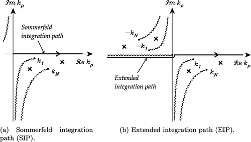
The integration path in (Equation46(46) )–(Equation54
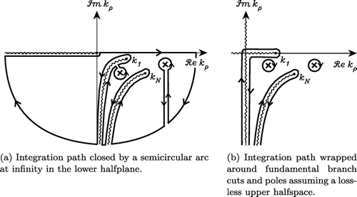
(54) ), often referred to as the Sommerfeld integration path (SIP), is along the positive real axis on the top Riemann sheet, as illustrated in Figure (a). The poles indicated in Figure are only meant to be representative; their actual location strongly depends on the media parameters. If the upper half-space is lossless (air), the branch point
lies on the real axis, and the SIP must be indented above it. Although effective methods for the computation of the Sommerfeld integrals along the SIP are available,[Citation83–Citation87] the rapid oscillations of the Bessel functions on the real axis make them inefficient for large
. In this case, more efficient integral representations can be obtained by a suitable deformation of the integration path and analytic continuation of integrand functions into the complex
-plane. However, in order to make the integration path deformable, we must first extend it to the whole real axis. The desired form [Citation1] is achieved by first expressing the Bessel function in (Equation37
(37) ) in terms of the Hankel functions using [Citation54]
(68)
Figure 5. Integration paths on the top Riemann sheet. A small loss in the upper half-space is assumed for better drawing clarity.
then introducing in the integrand containing the change of variable
, and making use of the circuital relation
(69)
whence(70)
provided that is an even (odd) function of
for even (odd) order
. Since the Hankel function introduces an extraneous logarithmic branch point at the origin with a branch cut along the negative real axis, the extended integration path (EIP) runs just under this branch cut, as illustrated in Figure (b). Both SIP and EIP are associated with the axial propagation representation of the layered medium Green functions.[Citation49]
An important attribute of the axial representation formulation is that the location of any poles of the integrand need not be determined. Also, it is the only formulation applicable in the so-called zero-offset case,[Citation88] where , which may be important in some geophysical and nondestructive testing applications. In practice, the SIP has to be deformed around the branch-point and pole singularities near the real axis, which however does not pose much difficulty.[Citation89,Citation90] The only limitation of this representation stems from the oscillatory behavior of the Bessel function on the real-axis path, which makes it impractical for if the horizontal range exceeds a few hundred wavelengths.Footnote14
2.5. Radial transmission representation
After locating the integrand singularities, it is possible to deform the EIP to obtain the radial transmission representation [Citation49,Citation94,Citation95] (or transverse spectral representation [Citation96]) of the Green functions, as we describe presently. Hence, following standard practice,[Citation97,Citation98] we close the integration path in (Equation70(70) ) down by a semi-circular arc at infinity on the top Riemann sheet, avoiding the branch point and pole singularities, as indicated in Figure (a). By Cauchy’s theorem, the integral over this closed path is zero. Also, in view of the large-argument form of the Hankel function, viz.
(71)
the semi-circle at infinity contributes nothing to the integral, as long as . Consequently, the real-axis path integral in (Equation70
(70) ) may be replaced by integrals around the hyperbolic branch cuts and the residue contributions arising from the presence of the poles, as illustrated in Figure (b). Note that on the fundamental branch cut associated with
,
and
, and similarly for the branch cut associated with
. It is thus convenient to use the positive real variables
or
as the variables of integration on the paths around the respective branch cuts. Using these substitutions, we may express the integral in (Equation70
(70) ) as
(72)
where and
denote the integrals around the two hyperbolic branch cuts,
is the
th pole of
and
is the corresponding residue. If
, where
and
, the residue may be found as
(73)
The first branch cut integral is given as(74)
where the square root branch should be selected for
, and where we have introduced the notation
(75)
for the folded spectral integrand function. Here, the plus (minus) superscript on indicates that every occurrence of
is directly replaced by the variable of integration with a plus (minus) sign. For more analytical details, see Appendix 4.
If the upper half-space is lossless, as we assume here, the branch cut associated with follows the real and imaginary axes, as indicated in Figure (b), and we may express
as [Citation99, p.134], [Citation83]
(76)
where is given in (Equation75
(75) ), where now the plus or minus superscript on
indicates that this function should be evaluated on Riemann sheet
or
, respectively. In the first integral above, we made a trigonometric substitution to remove the weak singularity at the branch point
,[Citation100] and in the second integral, we used the relationship [Citation54, Equation 10.27.8]
(77)
to express the Hankel function of imaginary argument in terms of the Macdonald function, which is exponentially decreasing.
The second branch cut integral in (Equation72(72) ) is also given by (Equation74
(74) ), except that
is replaced by
and the roles of
and
are interchanged. In the case of moist earth or seawater at radio frequencies, as well as for metals in the optical range, this integral is negligible in comparison with the first branch cut integral, hence we omit further details for brevity.
It will be instructive to derive the radial transmission representation of the Sommerfeld integral (Equation45(45) ), which represents the vector potential Green function for an infinite homogeneous space. In this case, the integrand function has branch points at
and no other singularities. Consequently,
, and we readily obtain
(78)
where the last integral follows directly from (Equation74(74) ) and (Equation77
(77) ) – with
replaced by
, to make these expressions applicable to the off-axis case. This Schelkunoff integral [Citation101] is the appropriate representation of the primary excitation when the method of scattering superposition is employed in the presence of cylindrical layers concentric with the
-axis, but is not applicable in the presence of planar layers perpendicular to the
-axis.Footnote15
The Sommerfeld pole, which is located on the top Riemann sheet, is always captured in the radial transmission representation and its residue contributes a pole wave in (Equation72(72) ). Note that, in view of (Equation71
(71) ), pole waves comprise a slow, inverse square root decay factor, and may thus potentially dominate the total surface field in the near and intermediate horizontal range, until the exponential decay eventually takes over. As we have shown in Section 2.3, the Sommerfeld pole is located to the left or to the right of the branch point
, depending on whether
or
, respectively, where
. In the former case, which arises for a lossy ground (or seawater) at radio frequencies, the corresponding pole wave is called a (radial–cylindrical) ZW. In the latter case, which arises for metals at THz and optical frequencies, this pole wave is called a SPP. Further, for noble metals in the visible range, the loss tangent may be small, in which case the SPP is also referred to as a Fano mode.[Citation82] The ZW and SPP are thus closely related – they satisfy the same resonance condition [Citation102] – and one may evolve into the other, as the media parameters change with frequency.Footnote16 One difference between ZW and SPP is that the former is a fast wave (meaning that its phase velocity exceeds the speed of lightFootnote17), while the latter is slow. Although ZW (or SPP) is always a part of the total surface field in the radial transmission representation, nothing can be said a priori regarding its relative importance. In fact, since the pole in the Sommerfeld case is located just below the hyperbolic branch cut, there is a potential for a substantial cancellation of ZW by the branch cut integral contribution. Note that such a compensation is less likely in the plasmonic case, where the pole is located to the right of the branch point, but it may still occur in the high-contrast case.
In view of the fact that ZW is coupled to a free mode of the layered medium, it is not unreasonable to attempt exciting it by a suitable source distribution.[Citation105,Citation106] However, a pure radial–cylindrical ZW can only be excited by a vertical line current of infinite extent, which is not physically realizable.[Citation107], [Citation108, p.10] With a finite dipole, ZW cannot be isolated from the total surface field – and the latter is what can actually be experimentally observed.[Citation109]
Finally, we note that although (Equation76(76) ) is expressed in a computationally convenient form, the closeness of the Sommerfeld pole to the integration path, as well as the rapid oscillations of the first integrand for large
, still adversely affect the efficiency of the radial transmission representation. As a result, this representation is not practical for horizontal ranges exceeding a few hundred wavelengths – similar to the axial transmission representation.Footnote18 These limitations are removed in the nonspectral representation, which will be demonstrated next.
2.6. Nonspectral representation
The nonspectral representation of the integral (Equation70(70) ) has the form
(79)
where and
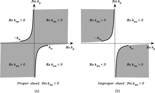
denote integrals around the vertical branch cuts, as illustrated in Figure , and the summation comprises all poles captured in the deformation, possibly including some on the improper Riemann sheets – the so called leaky wave poles [Citation96]. The shaded areas in Figure are the swaths of the improper Riemann sheets swept when the extended real-axis path is deformed to wrap around these branch cuts. Note that if the Sommerfeld pole is located to the left of
– as it would be in the lossy earth case, it is not captured and it does not explicitly contribute to the nonspectral representation of the integral. However, due to its close topological proximity to the downward leg of the integration path around
, this pole can still strongly influence the result. In the plasmonic case, this pole is located to the right of
, and is thus included in the residue summation in (Equation79
(79) ), but it may also strongly influence the branch cut integral. Comparing (Equation79
(79) ) and (Equation72
(72) ) in the Sommerfeld case, we note that
, where
is the ZW. Hence, in the nonspectral representation, the branch cut integral of the radial transmission representation associated with the branch point
and the contribution from the nearby Sommerfeld pole (i.e. the ZW) are treated collectively.
Figure 7. Integration path wrapped around vertical branch cuts and poles captured. The shaded areas are swaths of improper Riemann sheets swept in the path deformation.
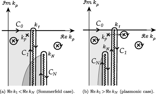
The validity of the contour deformation of Figure may be questioned on grounds that part of the infinite semi-circular arc in Figure now falls within the shaded area, which is on the improper Riemann sheet, potentially causing integrand terms like to grow without bound. However, as the radius of the arc approaches infinity within the finite-width vertical strip on the left side of the branch cut,
tends toward a positive real number, whence it follows that
must be bounded in this region.[Citation110] Consequently, on this part of the semi-circle the integrand of (Equation79
(79) ) will have the form of a bounded function of
multiplied by the Hankel function, which decays exponentially in the lower
half-plane, thus ensuring the vanishing of the integral over the arc at infinity.
We will presently address the computation of the branch cut integrals in (Equation79(79) ). Hence, upon changing the variable of integration via
, we express
as [Citation111]
(80)
with(81)
where now represents the jump in
as
changes sign across the vertical branch cut associated with
. In (Equation81
(81) ), we have introduced the normalized Hankel function
(82)
which approaches unity for . This substitution makes explicit the asymptotic
-dependence of the integrand in (Equation80
(80) ). The second branch cut integral,
, can similarly be expressed, upon the replacement
. As already mentioned in connection with the radial transmission representation, the contribution from this integral is typically negligible.
In order to correctly evaluate in (Equation81
(81) ), it is required to keep track of the Riemann sheets traversed as the integration in (Equation80
(80) ) proceeds along the vertical branch cut. The correct choices of the square root branches of
and
are readily determined with reference to Figure . Hence, in the Sommerfeld case, where
in Figure , we enforce
and
in computing
(on the left edge of the cut) and reverse the sign of
in computing
(on the opposite, right edge of the cut). In the plasmonic case, where
, the same rules should be followed in the selection of the
branch, but
should be enforced in
and
.
Figure 8. -plane in the vicinity of the origin, which corresponds to the branch point
in the
-plane.
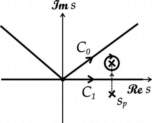
The mapping of the -plane into the
-plane introduced in (Equation80
(80) )–(Equation81
(81) ) is illustrated in Figure , where the contours
and
are images of the corresponding paths in Figure and
is the image of the Sommerfeld pole
. In the plasmonic case, this pole can cross the real axis and is then captured when the original path
is deformed into the real-axis path
. As already mentioned, the Sommerfeld pole may be located arbitrarily close to
– either on the left or on the right of the vertical branch cut – with the attendant spike in the integrand of (Equation80
(80) ), which makes the integration problematic. In such a case, the most reliable approach is to extract the contribution of the offending pole from the integrand and to add it back integrated in closed form [Citation14,Citation46,Citation112,Citation114]. The analysis is similar to the modified saddle-point nethod of Felsen and Marcuvitz [Citation56, Section 4]. Hence, we express the integral (Equation80
(80) ) asFootnote19
(83)
with(84)
where is the residue of
at the Sommerfeld pole
. With the pole term subtracted, the modified integral
in (Equation83
(83) ) is now amenable to numerical quadrature, while the compensating integral
has a closed-form representation, as shown in Appendix 3. Using these results in (Equation80
(80) ), we finally obtain
(85)
where is the numerical distance and
is the attenuation function, given in (EquationC5
(C5) ) and (EquationC8
(C8) ), respectively. It is important to note that
is discontinuous when the sign of
changes as the Sommerfeld pole crosses the real-axis integration path in Figure – and the Sommerfeld case turns into the plasmonic case. However, the resulting discontinuity in the branch cut integral (Equation85
(85) ) is exactly compensated by the residue term that must now be included in the nonspectral representation (Equation79
(79) ).
After the pole subtraction, the integrand of is well behaved and, assuming
h, is free of the oscillatory behavior plaguing the axial and radial propagation representations for large
. Furthermore, due to the exponential decay factor, the rate of convergence actually improves with increasing radial distance
. The latter property makes the nonspectral representation ideal for surface field computations – the only drawback being that leaky wave poles may be captured in the multilayer case.
2.7. Asymptotic evaluation of the branch cut integral
With the pole term extracted, this integrand of in (Equation83
(83) ) is smooth and rapidly decaying, due to the fact that the integration path
is the steepest descent path (SDP) for
h.[Citation112] Further, in view of the exponential factor, most of the contribution to the integral comes from the vicinity of
. Hence, we may approximate the integrand function by a Maclaurin expansion [Citation56, p.400], keeping just the first two terms. Since the leading term vanishes, we obtain
(86)
where and is given asFootnote20
(87)
Upon using (Equation86(86) ) in (Equation85
(85) ), we obtain the asymptotic form
(88)
applicable for large . In the above, we have introduced the modified attenuation function
(89)
which, in view of (EquationC10(C10) ), is
as
.
We may similarly derive the asymptotic form of the second branch cut integral, , where now
plays the role of
. However, since the Sommerfeld pole is typically located near
, the pole extraction is not required in this case. The contribution from this branch cut integral is negligible compared to
, except in the case of a low-loss lower half-space.
2.8. Discussion of the surface field
The surface field may be approximated by the asymptotic formula (Equation88(88) ), provided that the second branch cut contribution is negligible and no poles are captured in the nonspectral representation (Equation79
(79) ) – as in the Sommerfeld case. If a pole is intercepted – as in the plasmonic case – its contribution must be included in (Equation79
(79) ). For convenience, we will refer to the asymptotic branch cut integral (Equation88
(88) ) as the lateral wave and the contribution from any proper (top-sheet) pole captured in the nonspectral representation (Equation79
(79) ) will be called a trapped wave. We note that the horizontal range dependence of the lateral wave (Equation88
(88) ) is influenced by
and by
, and can be quite complex, due to the interplay of the two terms in the square brackets.Footnote21 It is clear, however, that sufficiently far from the dipole, the range dependence is
, and this behavior is governed by
, which is dictated by the limit value of the spectral integrand at the branch point
.Footnote22 As regards the near- and intermediate-zone behavior, we can be more definitive in the high-contrast case, when the lateral wave assumes the simpler form (EquationD12
(D12) ). Since the attenuation function
approaches unity for
, the field dependence near the dipole is is
, and it evolves into
dependence with increasing
, in view of the asymptotic form (EquationC10
(C10) ). We may thus consider the
point as a demarcation point where the transition (knee) from the
to the
asymptote begins, which upon using (EquationD9
(D9) ) yields
(90)
The asymptotic form (Equation88(88) ) also reveals that the Sommerfeld pole plays a role in the surface field even when not captured in the nonspectral representation (Equation79
(79) ). In fact, the exponential term in (EquationC8
(C8) ), along with the other factors that appear in (Equation88
(88) ), is exactly the ZW.[Citation27,Citation115] This ZW, however, can only be significant in a limited horizontal range, as it is cancelled for large
, in view of the asymptotic behavior (EquationC10
(C10) ) of
.Footnote23 In the plasmonic case, where
and the pole is captured and contributes an explicit residue term in (Equation79
(79) ), its influence may persist over a larger horizontal range, in view of the slowly decaying
amplitude factor – provided that the exponential decay is small.
3. Numerical results
We include here sample numerical results to elucidate the properties of the alternative field representations and the behavior of the surface fields for several representative cases. However, in view of the recent misguided attempts in the literature to cast doubt on the existence of the Sommerfeld pole on the top sheet,[Citation18,Citation19] it is perhaps appropriate to begin with an example illustrating its effect on the Sommerfeld integrals. Hence, consider a vertical dipole placed at m above a lossy ground with
and conductivity
mS/m at
MHz (
m), which results in
and the Sommerfeld pole at
. For this case, in Figure we plot the logarithmic magnitude of the integrand of
at
m, where
is given by (EquationD5
(D5) ), over a square region in the normalized
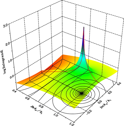
-plane, which includes the branch point. The plot of the integrand along the original SIP, which follows the real axis along the upper edge of the branch cut, is also included. Note that the Sommerfeld pole, which is located very near the branch point on Riemann sheet
and is “hidden” just below the branch cut, causes a spike in
along the SIP. This spike in the vicinity of the pole, as well as the infinite derivative of
at the branch point, make the original SIP problematic – although some authors still use it after annihilating the branch point singularity by either subtraction the singular term or local variable transformation.[Citation117,Citation118] As already mentioned in connection with the axial propagation representation, another simple remedy is a detour into the 1st quadrant of the complex
-plane, which skirts the singularities and then rejoins the real-axis tail. In view of the exponential growth of the Bessel function, this detour may not veer off too far into the complex plane, but its shape is otherwise not critical. Here, we have opted for the piecewise linear rooftop contour,[Citation90] with the height inversely proportional to
, and on this path the integrals are computed by the adaptive Patterson rule.[Citation119] On the remaining real axis tail, we apply Gaussian quadrature between the asymptotic zeros of the Bessel function and extrapolate the resulting slowly convergent partial sums by the Levin-type Mosig–Michalski transformation.[Citation84], [Citation120, p.102] Note that there is no need to determine the exact location of the poles of the integrand. We use this approach here as a reliable benchmark method for the radial transmission and nonspectral representations, provided that the horizontal range does not exceed a few hundred wavelengths.
As the first example, consider a vertical dipole located at m over dry ground with
and
mS/m at
MHz (
m). In this case,
and the Sommerfeld pole is at
. Note that this is a low-contrast, low-loss Sommerfeld case, hence the pole wave is classified as Brewster mode. Plots of
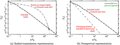
vs. the horizontal distance along the surface, obtained by the radial transmission and nonspectral representations, are shown in Figure (a) and (b), respectively.
Here and henceforth, we also include the benchmark result (indicated by triangle symbols) computed using the axial transmission representation with the modified SIP, as explained above. The -branch cut contribution is not negligible in this case and its effect is included in the results. Note that the Brewster mode is strongly excited in the radial propagation representation, but is mostly cancelled by the
-branch cut contribution. In the nonspectral representation, the Sommerfeld pole is not captured and the asymptotic lateral wave is practically indistinguishable from the total field when
. Both representations being rigorous, the total fields plotted in Figure (a) and (b) are, of course, identical. However, the nonspectral representation is much more efficient, especially when the closed-form lateral wave (Equation88
(88) ) is employed.
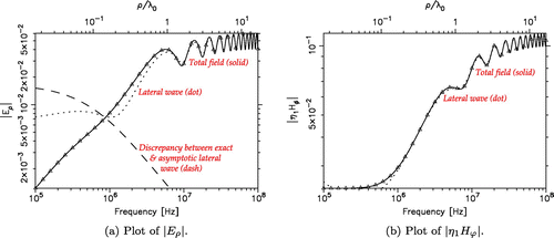
Continuing with the dry ground example, in Figure we present nonspectral representation results showing the field behavior at a fixed distance m from a vertical dipole placed at the surface (
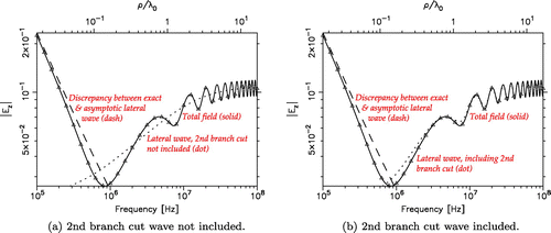
), as the frequency is varied over three decades. Similar case was recently considered by Parise [Citation121]. The plots of
in Figure illustrate the effect of neglecting the 2nd branch cut integral contribution – confirming that this is not allowed in this low-contrast case. Note that the undulations in the total field are clearly a result of the interference of the two branch cut waves. Plots of
and
for the same case are shown in Figure , where the 2nd branch cut contribution is included. Again, the closed-form lateral wave captures the surface field behavior with remarkable accuracy if the horizontal distance exceeds one wavelength.
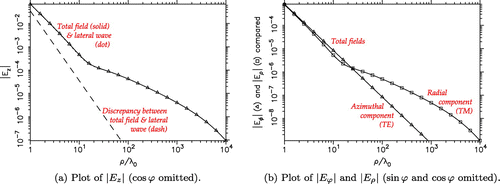
In the next example, the vertical dipole is at m above seawater with
and
S/m, also at
MHz. In this case,
and the Sommerfeld pole is at
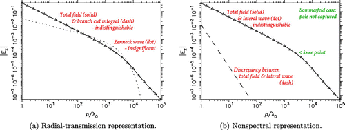
. Note that this is a high-contrast, high-loss Sommerfeld case, hence the pole wave is classified as ZW and the
-branch cut contribution may be safely neglected. The corresponding radial transmission and nonspectral representation results are presented in Figure (a) and (b), respectively.
Figure 11. Plot of vs. frequency at a fixed distance from the source for the dry ground case. Nonspectral representation is employed.
We note that the ZW is weakly excited in the radial transmission representation and makes little impact on the total field.Footnote24 In the nonspectral representation, the Sommerfeld pole is not captured and the total field is well represented by the lateral wave. The knee point, where the transition from the
to the
asymptote begins, corresponds to
, or
km. To conserve space, we do not show the plots of
and
, which are very similar to those in Figure , except that the former is approximately two orders of magnitude lower in strength. For the same example, in Figure we give nonspectral representation results for a horizontal (
-oriented) dipole, still at
m. Comparing the
field plots in Figures (b) and (a), we note that the latter is much smaller in magnitude, which may be attributed to the fact that a horizontal dipole has a negative image in a conducting half-space. It is also interesting that the horizontal dipole fields exhibit a
decay rate in the near zone (up to
wavelengths), which in the case of
and
then turns into a
behavior in the intermediate range. The azimuthal component,
, is a TE wave, for which there is no Sommerfeld pole, and this component decays as
in the entire horizontal range. Mahmoud and Antar [Citation123] state that the TE
component is dominant in the far zone, but this is not borne out by the results in Figure (b), where both the triangle and square symbols denote benchmark results.
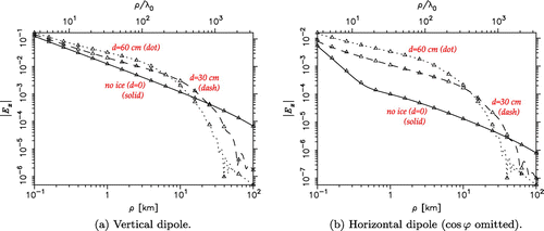
Staying with the seawater case, we next examine the effect of an ice layer () of varying subwavelength thickness
– with the dipole remaining at
m above the ice surface. Similar case was recently considered by Mahmoud and Antar [Citation123]. In Figure (a) and (b), we plot the total surface fields – obtained using the nonspectral representation, for the vertical and horizontal dipoles, respectively. The
-branch cut integral is computed using the asymptotic lateral wave expression (Equation88
(88) ), with the contribution from the branch cut associated with seawater safely neglected. Hence, the total field comprises the lateral wave and – if the ice layer is present, the trapped mode. The excellent agreement of the asymptotic and exact benchmark results should be noted. For easy reference, we have also included in the plots the bare seawater case, which was already discussed above. With the ice layer added, the Sommerfeld pole migrates to
for
cm and to
for
cm. Hence, as soon as a thin ice layer appears, the Sommerfeld case turns into a plasmonic case and the trapped wave is included in the nonspectral representation (Equation79
(79) ). For both the vertical and horizontal dipoles, the ice cover enhances the surface field in the
km range – more significantly so in the latter case. This enhancement is due to the trapped wave, which exhibits the
decay rate in the range where the lateral wave decays as
. For
exceeding
km, the exponential decay factor in the trapped wave dominates, eventually forcing it to fall below the lateral wave in magnitude – which occurs at a point where the latter follows the
asymptote.Footnote25 The characteristic wiggles in the total field observed near this point are due to the interference of the lateral and trapped waves when their magnitudes become comparable.
Figure 16. Nonspectral representation results for the GPR example and a table of the poles included.
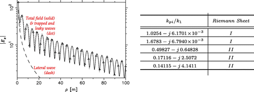
The next example pertains to GPR detection of leaking pipes in the shallow sub-surface at MHz (
m).[Citation47] The vertical dipole is in air at the top surface (
) of a three-layer half-space comprising, from top to bottom, a dry sand bar (
) of thickness
m, an air gap of thickness
cm, and water logged soil (
,
S/m). The nonspectral representation results for this case are plotted in Figure , where we also list the poles that were included. The first two poles in the table are proper surface wave poles and the remaining three are improper leaky wave poles. The former are associated with two trapped modes in the sand bar, whose interference creates the undulations observed in Figure . The first pole listed, which is close to the branch point, was treated as the Sommerfeld pole in the nonspectral representation. The lateral wave is seen to be negligible, except near the source, and the trapped waves dominate in the horizontal range considered. To bring the nonspectral representation result in agreement with the benchmark, the contributions from the three leaky wave poles, also captured by the deformed integration path, had to be included. These waves are heavily damped, but contribute significantly in the vicinity of the dipole.
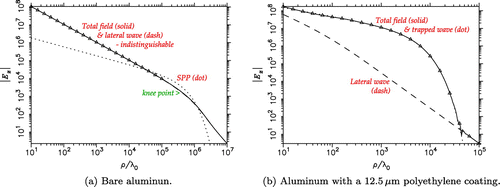
As the next example, consider a vertical dipole at m above aluminum with
and
at
THz (
m). In this case,
and the pole is found at
. Note that this is a high-contrast, high-loss plasmonic case, hence the Sommerfeld pole is captured in the nonspectral representation and the pole wave is classified as SPP. We also examine the effect of a thin,
m (
) of polyethylene coating layer with
on top of Al.[Citation45] The pole is now found at
and it contributes a trapped wave. The nonspectral representation results for the bare and coated Al configurations are presented in Figures (a) and (b), respectively. In the former case, the SPP is weakly excited and although its contribution slightly exceeds in magnitude the lateral wave in the intermediate horizontal range, it combines with it destructively, so there is no noticeable enhancement in the total surface field magnitude. The propagation length and depth of penetration in air of the SPP are found from (Equation66
(66) ) as
m and
cm, respectively. Hence, the propagation length is very large and the wave is loosely bound to the surface. However, since the contribution of this mode to the total surface field is insignificant, we contend that it would be futile to try to detect its presence experimentally, as recently endeavored by Jeon and Grischkowsky [Citation31]. The
knee point of the lateral wave is found at
, or
m, whereas the Al sheet used in the surface wave measurements mentioned above was less than one meter long. In the coated Al case, the trapped wave with the
dependence is strongly excited and it dominates the total field over a wide horizontal range, until the exponential decay factor makes it fall below the lateral wave, which is in transition to the
asymptote at this point. This wave is much more tightly bound to the surface than the SPP in the bare Al case.Footnote26 As a result, a larger fraction of the mode energy is concentrated in the lossy conductor, which accelerates the onset of the exponential decay, as compared to the bare metal case.
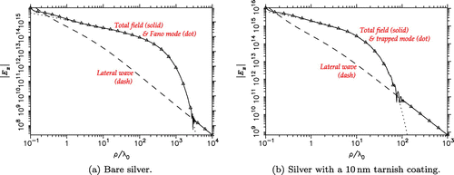
In the next example, the vertical dipole is placed at nm above silver half-space at
nm in the visible band. By fitting the experimental dielectric function data for Ag [Citation124] with a low-order partial fraction (PF) model,[Citation125] we find
and the Sommerfeld pole at
. Note that this is a high-contrast, low-loss plasmonic case, hence the pole is captured in the nonspectral representation and the pole wave is classified as Fano mode. The contribution of the
branch cut is negligible, because
has a large negative imaginary part. We also consider the effect of a thin,
nm silver sulfide tarnish layer, which builds when silver is exposed to air. For Ag
S, by fitting the tabulated data [Citation126] with the PF model,[Citation125] we find
and a numerical search reveals that the pole has now migrated to
and it contributes a trapped mode. The nonspectral representation results for the bare and tarnished Ag configurations are presented in Figure (a) and (b), respectively. Note that, due to the low losses of Ag in the visible range, the SPP is strongly excited - both in the bare metal and coated cases.Footnote27 The propagation length and depth of penetration in air of the Fano mode are found from (Equation67
(67) ) as
m and
m, respectively. Hence, the propagation length is large and the mode is confined to the surface, which is exploited in plasmonic sensor applications.[Citation127] In the coated Ag case, the trapped mode is more heavily damped, due to the additional losses in the tarnish layer, with the concomitant decrease in the propagation range.
Figure 20. PF model fit [Citation125] of the tabulated dielectric function of Cr,[Citation128] including the range where .
![Figure 20. PF model fit [Citation125] of the tabulated dielectric function of Cr,[Citation128] including the range where .](/cms/asset/715a3e6a-6e93-4bb9-a540-d5dd038f3ae1/tewa_a_1093964_f0020_oc.gif)
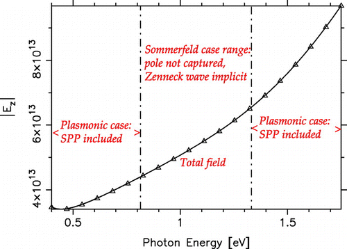
As the final example, we consider a vertical dipole located at nm above a chromium half-space, and compute the surface field at a fixed distance
m from the dipole as the frequency (photon energy) is varied in the near-infrared band. The nonspectral representation results for this case are shown in Figure . Since in the selected frequency range
of Cr passes from negative values to positive and back,[Citation35] as indicated in Figure , the Sommerfeld pole migrates across the vertical branch cut and there is a transition from the plasmonic case (the pole is captured and contributes a SPP) to the Sommerfeld case (the pole is not captured, but the ZW is implicit in the groundwave) and back. Hence, the total field plot in Figure includes the lateral wave and the SPP in the plasmonic range, and just the lateral wave in the Sommerfeld range. This plot is continuous, which confirms that the jumps in the attenuation function (EquationC8
(C8) ) as the Sommerfeld pole crosses the vertical branch cut (or the real axis in the
-plane – see Figure ) are exactly compensated by the SPP, which is either included or not in nonspectral representation (Equation79
(79) ). This example thus underscores the close relationship between the ZW and SPP.
4. Summary and conclusions
We have revisited the classical half-space problem of Sommerfeld, with extensions to a layered half-space and plasmonic media and a focus on the surface fields away from the dipole. A new ab initio solution of this problem is presented and alternative field representations – termed axial transmission, radial transmission, and nonspectral – are derived and their relative merits discussed. Using the nonspectral representation as the point of departure, a closed-form asymptotic expression for the surface field is derived. Based on this expression, the surface field behavior is discussed and the rôle of the ZW and SPP is elucidated. The theoretical development is supported by representative numerical examples, which cover a wide spectrum – from radio waves to visible light. In all cases considered, the closed-form asymptotic formulas are remarkably accurate for . The main points of this study may be recapitulated as follows:
The total surface field of a Hertzian dipole may be decomposed into two branch cut contributions associated with the upper and lower media plus possible pole waves. The branch cut contribution associated with the upper medium (air) is called a lateral wave and it typically dominates the total surface field; the contribution from the second branch cut (associated with the lossy half-space) is negligible if the media contrast is sufficiently high.
In the case of a homogeneous, lossy half-space, the Sommerfeld pole does exist on the top (proper) Riemann sheet and is always captured in the radial transmission representation (using hyperbolic branch cuts).
Depending on the real part of the dielectric constant, the pole may be located to the left (Sommerfeld case) or to the right (plasmonic case) of the branch point associated with the upper medium (air).
In the Sommerfeld case, the pole wave is slow (meaning that its phase velocity exceeds the speed of light) and is called a ZW, and in the plasmonic case, this wave is fast and is called a SPP. In the low-loss plasmonic case, the SPP is also referred to as a Fano mode. In the multilayer half-space case, the proper pole waves are called trapped modes. All pole waves are characterized by a small,
, decay rate in the small to moderate horizontal ranges.
In the nonspectral representation (using vertical branch cuts), the pole is captured in the plasmonic case, but not in the Sommerfeld case.
The appearance or not of the ZW in a particular surface field representation does not prove or disprove the physical reality of this wave.
In the Sommerfeld case, the ZW always contributes to the total surface field, either explicitly (in the radial propagation representation) or implicitly (in the nonspectral representation). However, this wave may only be significant in the near to intermediate horizontal range, and is never a dominant contributor to the total surface field. Consequently, it is not feasible to experimentally detect the presence of the ZW in the surface field of a simple antenna.
The range dependence of the lateral wave is determined by a complex parameter
called numerical distance, which depends not only on
, but also on the dielectric constant of the lossy half-space. The lateral wave decays as
near the dipole and the decay rate increases with increasing
, eventually reaching the
asymptote. The transition (knee) to the
asymptote begins at the
value given by
.
In the case of noble metals in the THz (far-infrared) range, the SPP is weakly excited and is weakly bound to the surface, and its contribution to the total surface field is negligible. When the metal is coated with a thin, low-loss dielectric layer, the SPP becomes a trapped mode, which is strongly excited and much more tightly bound to the surface.
In the case of noble metals in the visible range, where the losses are very small, the SPP (Fano mode) is strongly excited and it may dominate the surface field behavior over a thousand-wavelength range. When a Fano or a trapped mode is present, the total surface field initially exhibits the
decay, until the exponential decay factor eventually brings it below the
asymptote of the lateral wave.
The ZW and SPP are closely related – they satisfy the same resonance condition – and one may evolve into the other with the change of frequency.
Additional information
Funding
Notes
No potential conflict of interest was reported by the authors.
Dedicated to the memory of Professor James R. Wait.
1 The horizontal dipole case was first solved by von Hoerschelmann [Citation5] in a PhD thesis supervised by Sommerfeld.
2 The subtle error (just a wrong sign in one of three terms [Citation8]) – never acknowledged by the author – was first publicized by Norton in 1935.[Citation9]
3 One early theory, promulgated in several papers by Kahan and Eckart and soon debunked by Bouwkamp [Citation15] and Ott [Citation16], was that Sommerfeld erroneously included the ZW in the field representation when he deformed the integration path around the hyperbolic branch cuts. This controversy was thoroughly covered by Baños [Citation17, Section 4.10], who ended with a hopeful plea that there would be no more papers attempting to disprove the existence of the ZW term in the Sommerfeld field representation. His wish was nor granted, however, as we again see misguided attempts to deny the existence of the Sommerfeld pole on the top Riemann sheet.[Citation18,Citation19] Another, more long-lasting hypothesis was that Sommerfeld committed a sign error in choosing the wrong branch of the square root of the complex numerical distance parameter that appears in his formula. However, in 2004 Collin [Citation14] found no sign inconsistency in Sommerfeld’s 1909 derivation and concluded that “there are inherent limitations in Sommerfeld’s solution, but they are not caused by a sign error” – where by “limitations” he presumably meant the exceedingly small radii of convergence of the series expansions employed by Sommerfeld, but he did not point out any specific mathematical illegality that lead to the sign error in the asymptotic groundwave formula. Hence, it would appear that the exact cause of the sign error in Sommerfeld’s 1909 paper remains unknown to this day. This is a moot point, however, which now squarely falls within the realm of the history of science, since the correct asymptotic solution has long been available, as indicated above.
4 However, this last formulation was later found to be incomplete, as it does not properly account for the trapped wave.[Citation14,Citation44]
5 So named, because the integration path is not confined to the proper Riemann sheet.
6 The time convention is implied.
7 Source coordinates are distinguished by primes.
8 Unit vectors are distinguished by carets.
9 Note that is the zero-order Bessel function.[Citation54].
10 Here, we use (Equation17(17) ) and the relation
, where the prime denotes differentiation with respect to the argument of the Bessel function.
11 Our proof of the existence of the Sommerfeld pole on the top sheet is similar to that originally given by Sommerfeld [Citation1,Citation3] and later by other authors [Citation20,Citation72,Citation73], [Citation74, p.355], except that we have extended it to plasmonic media with . We should also mention here a note by Gogoladze [Citation75], purporting to prove the nonexistence of the Sommerfeld pole on the top sheet. Also, Schelkunoff [Citation76, p.430] gives a proof that there is no pole on the top sheet – however, he seems to assume a lossless half-space. This proof has been uncritically embraced by Sarkar et al. [Citation18,Citation77], who also deny the existence of the Sommerfeld pole on the top sheet. The lossless case is also tacitly assumed by Chew [Citation78, p.99], when he states that only in the plasmonic case is the pole located on the top sheet.
12 This name derives from the fact that the (original) ZW [Citation7] may be set up by assuming a plane wave impinging in air on the lossy half-space at the (complex) Brewster angle,[Citation79] where the latter is determined by the value of the transverse propagation constant , which makes the numerator of the reflection coefficient (EquationA10
(A10) ) vanish. Hence, only the incident and transmitted waves exist at this angle, and both must decay in magnitude away from the interface, in order to constitute a surface wave. Since the incident wave propagates toward the interface, with the
-dependent factor
, and it increases in magnitude as it does so, we must have
. The transmitted wave in the lower half-space propagates away from the interface and vanishes for
, hence
. Consequently,
is a root of the numerator of the reflection coefficient (EquationA10
(A10) ) on Riemann sheet
. Note that in the Sommerfeld half-space problem, the ZW arises as a resonant solution, i.e. it is a mode that exists in the absence of any incident field, and thus the reflection coefficient looking into the half-space must be infinite.[Citation80] To set up such a mode, we postulate waves propagating away from the interface and vanishing for
. Hence, the propagation constant
is a root of the denominator of the reflection coefficient on sheet
, where both
and
.
13 Incidentally, one should resist the temptation to ascribe any physical significance the the particular threshold numbers , as they are based on approximate expansions (Equation64
(64) ) and (Equation66
(66) ).[Citation81].
14 Incidentally, the overriding difficulty is not due to the oscillatory integral tail, which can be effectively computed by partition-extrapolation methods,[Citation84,Citation86,Citation91,Citation93] but due to the rapid oscillations of the integrand on the initial, finite-length path segment.
15 The Schelkunoff integral was recently misused in this way by Sarkar et al. [Citation18,Citation19] to derive a spurious radial transmission representation – called the “Schelkunoff formulation” and claimed to be rigorous – which is missing both the ZW and the second branch cut contribution. The fallacy of this formulation was already pointed out by Janaswamy [Citation20], but the criticism was rejected by the authors [Citation21].
16 This is contrary to the recent claim of Dyab et al. [Citation103] that there is no relationship “whatsoever” between SPP and ZW – since, according to these authors, the latter “does not exist.”
17 The group velocity of ZW also exceeds the speed of light,[Citation104] but not its energy transport velocity.[Citation81].
18 Hence, the radial transmission representation is not quite the panacea for the oscillatory integrand behavior it is sometimes purported to be in the literature.[Citation18].
19 Note that the subtracted pole term has been purposely selected to have a zero limit at the origin, where also vanishes.
20 This limit is discussed in more detail in Appendix 4.
21 It should be borne in mind here that and
are also
-dependent, unless
.
22 For TE fields, where the Sommerfeld pole is absent (assuming nonmagnetic media), in (Equation88
(88) ) and the lateral wave exhibits only the inverse square
-dependence.
23 As a result of the already mentioned elusive error in Sommerfeld’s 1909 paper,[Citation1] there was no asymptotic cancellation of the ZW in his original groundwave formula. Hence, the deleterious effect of this error was that the groundwave seemed to be an important factor in the radio wave propagation along the surface of the earth.[Citation116] It is interesting that Sommerfeld inadvertently arrived at a formula applicable in the plasmonic case. Again, Sommerfeld later gave the correct expression in his 1926 paper.[Citation2].
24 We should mention here the recent attempts of Petrillo et al. [Citation122] to design an efficient ZW launcher, in hopes of extending the range of the maritime surface wave radar. Using a two-dimensional radial transmission representation for that purpose, they arrived at some dipole array configurations, which they describe as “realistic, but still unrealizable.”
25 The knee point, which was at km in the bare seawater case, occurs much sooner when ice is present – it is at
km for a
cm ice layer, and as close as
km when the ice thickness is doubled to
cm.
26 Gong et al. [Citation45] call this phenomenon the “THz surface wave collapse.” Note that they refer to the SPP as the “Zenneck THz surface wave.”
27 This is in contrast with the bare Al in the THz range, where the SPP excitation was weak.
29 Henceforth, we omit the superscript for notational simplicity.
30 Note that these branch cuts are in the 1st and 3rd quadrants if the time convention is used.
31 Here, a lossless medium should be treated as a limit of the corresponding lossy medium as losses approach zero.
32 Note that on the hyperbolic extensions of the branch cuts, indicated by the dotted lines.
33 Sommerfeld called this the similarity law (Ähnlichkeitsgesetz) of wireless telegraphy.[Citation1].
34 We henceforth omit the superscript for notational simplicity.
35 Henceforth, square roots with positive real parts are implied.
References
- Sommerfeld A. Über die Ausbreitung der Wellen in der drahtlosen Telegraphie [On the propagation of waves in wireless telegraphy]. Ann. Phys. 1909;28:665–736.
- Sommerfeld A. Über die Ausbreitung der Wellen in der drahtlosen Telegraphie [On the propagation of waves in wireless telegraphy]. Ann. Phys. 1926;81:1135–1153.
- Sommerfeld A. Drahtlose Telegraphie [Wireless telegraphy]. In: Frank P, von Mises R, editors. Die Differential- and Integralgleichungen der Mechanik und Physik, part II [Differential and integral equations of mechanics and physics]. 2nd ed. Chapter 23, New York (NY): Rosenberg; 1943. p. 918–977.
- Sommerfeld A. Partial differential equations in physics. Vol. VI, Lectures on theoretical physics. New York (NY): Academic Press; 1949.
- von Hoerschelmann H. Über die Wirkungsweise der geknickten Markonischen Senders in der drahtlosen Telegraphie [On the operation of a bent Marconi transmitted in wireless telegraphy]. Jahrb drahtl. Telegr. Teleph. 1911;5:14–34.
- Noether F. Ausbreitung elektrischer Wellen über der Erde [Propagation of electrical waves over earth]. In: Rothe R, Ollendorff F, Pohlhausen K, editors. Chapter E, Funktionentheorie und ihre anvendung in der technik [Function theory and its application in technology]. Berlin: Springer; 1931. p. 154–170.
- Zenneck J. Über die Fortpflanzung ebener elektromagnetischer Wellen längs einer ebenen Leiterfläche und ihre Beziehung zur drahtlosen Telegraphie [On the propagation of plane electromagnetic waves along a flat surface and its relationship to wireless telegraphy]. Ann. Physik. 1907;23:846–866.
- Niessen KF. Zur Entscheidung zwischen den beiden Sommerfeldschen Formeln für die Fortpflantzung von drahtlosen Telegraphie [On deciding between the two Sommerfeld’s formulas for the propagation of wireless telegraphy]. Ann. Phys. 5 Folge. 1937;29:585–596.
- Norton KA. Propagation of radio waves over a plane earth. Nature. 1935;135:954–955.
- Maclean TSM, Wu Z. Radiowave propagation over ground [Propagation of electromagnetic waves over a flat conductor]. London: Chapman & Hall; 1993.
- Weyl H. Ausbreitung elektromagnetischer Wellen über einem ebenem Leiter [Propagation of electromagnetic waves over a flat conducto]. Ann. Physik. 1919;365:481–500.
- Kockel B. Die Sommerfeldsche Bodenwelle [The groundwave of Sommerfeld]. Ann. Physik., 7 Folge. 1958;1:146–156.
- Wait JR. The ancient and modern history of EM ground-wave propagation. IEEE Antennas Propag. Mag. 1998;40:7–24.
- Collin RE. Hertzian dipole radiating over a lossy earth or sea: Some early and late 20th-century controversies. IEEE Antennas Propag. Mag. 2004;46:64–79.
- Bouwkamp CJ. On Sommerfeld’s surface wave. Phys Rev. 1950;80:294.
- Ott H. Oberflächenwelle und keine Ende [Surface wave and no end]. Archiv elektr Übertrag. 1951;5:343–346.
- Baños A. Dipole radiation in the presence of a conducting half-space. New York(NY): Pergamon Press; 1966.
- Dyab WM, Sarkar TK, Salazar-Palma M. A physics-based Green’s function for analysis of vertical electric dipole radiation over an imperfect ground plane. IEEE Trans. Antennas Propag. 2013;61:4148–4157.
- Sarkar TK, Dyab WM, Abdallah MN, Salazar-Palma M, Prasad MVSN, Ting SW. Application of the Schelkunoff formulation to the Sommerfeld problem of a vertical electric dipole radiating over an imperfect ground. IEEE Trans. Antennas Propag. 2014;62:4162–4170.
- Janaswamy R. Comments on ‘A physics-based Green’s function for analysis of vertical electric dipole radiation over an imperfect ground plane’. IEEE Trans. Antennas Propag. 2014;62:4907–4910.
- Dyab WM, Sarkar TK, Salazar-Palma M. Reply to: Comments on ‘A physics-based Green’s function for analysis of vertical electric dipole radiation over an imperfect ground plane’. IEEE Trans. Antennas Propag. 2014;62:4910–4913.
- Norton KA. The propagation of radio waves over the surface of the earth and in the upper atmosphere-part II: The propagation from vertical, horizontal, and loop antennas over a plane earth of finite conductivity. Proc. IRE. 1937;25:1203–1237.
- van der Pol B, Niessen KF. Über die Ausbreitung elektromagnetischer Wellen über eine ebene Erde [On the propagation of electromagnetic waves over flat earth]. Ann. Phys., 5 Folge. 1930;6:585–596.
- van der Pol B. Theory of the reflection of the light from a point source by a finitely conducting flat mirror, with an application to radiotelegraphy. Physica. 1935;2:843–853.
- Chang DC, Fisher RJ. A unified theory on radiation of a vertical electric dipole above a dissipative earth. Radio Sci. 1974;9:1129–1138.
- Milsom JD. Surface waves, and sky waves below 2 MHz. Hall MPM, Barclay LW, Hewitt MT, editors. Chapter 15, Propagation of radiowaves. London: The Institution of Electrical Engineers; 1996. p. 307–334.
- Wait JR. Excitation of surface waves on conducting, stratified, dielectric-clad, and corrugated surfaces. J. Res. Nat. Bureau Stand. 1957;59:365–377.
- King RJ. Electromagnetic wave propagation over a constant impedance plane. Radio Sci. 1969;4:225–268.
- Green H. Derivation of the Norton surface wave using the compensation theorem. IEEE Antennas Propag. Mag. 2007;49:47–57.
- King RWP. Electromagnetic field of a vertical dipole over an imperfectly conducting half-space. Radio Sci. 1990;25:149–160.
- Jeon TI, Grischkowsky D. THz Zenneck surface wave (THz surface plasmon) propagation on a metal sheet. Appl. Phys. Lett. 2006;88:061113-1–061113-3.
- Novotny L. Allowed and forbidden light in near-field optics. I. A single dipolar light source. J. Opt. Soc. Am. A. 1997;14:91–104.
- Maier SA, Atwater HA. Plasmonics: localization and guiding of electromagnetic energy in metal/dielectric structures. J. Appl. Phys. 2005;98:011101-1–011101-10.
- Gordon R. Surface plasmon nanophotonics: a tutorial. IEEE Nanotechnol Mag. 2008;13–18.
- Sarrazin M, Vigneron JP. Light transmission assisted by Brewster-Zennek modes in chromium films carrying a subwavelength hole array. Phys. Rev. B. 2005;71:075404-1–075404-5.
- Sihvola A, Qi J, Lindell IV. Bridging the gap between plasmonics and Zenneck wave. IEEE Antennas Propag. Mag. 2010;52:124–136.
- Gan CH, Lalouat L, Lalanne P. Optical quasicylindrical waves at dielectric interfaces. Phys. Rev. B. 2011;83:085422-1–085422-6.
- Grosskopf J. Das Strahlungsfeld eines vertikalen Dipolsenders über geschichtetem Boden [Radiation field of the vertical dipole transmitter over stratified ground]. Hochfrequenztechnik und Elektroakustik. 1942;60:136–141.
- Wait JR. Radiation from a vertical electric dipole over a stratified ground. IRE Trans. Antennas Propag. 1953;AP-1:9–11.
- Wait JR. Influence of a sub-surface insulating layer on electromagnetic ground wave propagation. IEEE Trans. Antennas Propag. 1966;AP-14:755–759.
- Wait JR, Schlak GA. New asymptotic solution for the electromagnetic fields of a dipole over a startified medium. Electron. Lett. 1967;3:421–422.
- Wait JR. Electromagnetic waves in stratified media. New York (NY): Pergamon Press; 1970.
- King RWP, Sandler SS. The electromagnetic field of a vertical electric dipole over the earth or sea. IEEE Trans. Antennas Propag. 1994;42:382–389.
- Wait JR. Comments on ‘The electromagnetic field of a vertical electric dipole in the presence of a three-layered region’ by Ronold W.P. King and Sheldon S. Sandler. Radio Sci. 1998;33:251–253.
- Gong M, Jeon T-I. Grischkowsky D. THz surface wave collapse on coated metal surfaces. Opt. Express. 2009;17:17088–17101.
- Nevels RD, Michalski KA. On the behavior of surface plasmons at a metallo-dielectric interface. J. Lightwave Technol. 2014;32:3299–3305.
- Cross JD, Atkins PR. Electromagnetic propagation in four-layered media due to a vertical electric dipole: a clarification. IEEE Trans. Antennas Propag. 2015;63:866–870.
- Tai CT. Dyadic Green functions in electromagnetic theory. 2nd ed. New York (NY): IEEE Press; 1994.
- Felsen LB. Alternative Green’s function representations for a grounded dielectric slab. Toraldo di Francia G, editor. Onde Superficiali: Lectures given at the Centro Internazionale Matematico Estivo (C.I.M.E.), Varenna (Como), Italy, September 4--13, 1961. Berlin: Springer; 2011. p. 191–219.
- Harrington RF. Time-harmonic electromagnetic fields. New York (NY): McGraw-Hill; 1961.
- Dmitriev VI. General method for computing the electromagnetic field in a layered medium (in Russian). Vol. 10, Computational methods and programming. Moscow: MGU Press; 1968. p. 55–65.
- Dmitriev VI, Silkin AN, Farzan R. Tensor Green function for the system of Maxwell’s equations in a layered medium. Comput. Math. Model. 2002;11:107–118.
- Michalski KA. The mixed-potential electric field integral equation for objects in layered media. Arch. ElekÜbertragung. 1985;39:317–322.
- Olver FWJ, Lozier DW, Boisvert RF, Clark CW, editors. NIST handbook of mathematical functions. Cambridge: Cambridge University Press; 2010.
- Tyras G. Radiation and propagation of electromagnetic waves. New York (NY): Academic Press; 1969.
- Felsen LB, Marcuvitz N. Radiation and scattering of waves. Englewood Cliffs (NJ): Prentice Hall; 1973.
- Friedman B. Principles and techniques of applied mathematics. New York (NY): Wiley; 1956.
- Marcuvitz N, Schwinger J. On the representation of the electric and magnetic fields produced by currents and discontinuities in wave guides. I. J. Appl. Phys. 1951;22:806–819.
- Michalski KA, Mosig JR. Multilayered media Green’s functions in integral equation formulations. IEEE Trans. Antennas Propag. 1997;45:508–519. Invited review paper.
- Ishimaru A. Electromagnetic wave propagation, radiation, and scattering. Englewood Cliffs (NJ): Prentice Hall; 1991.
- Ishimaru A, Thomas JR, Jaruwatanadilok S. Electromagnetic waves over half-space metamaterials of arbitrary permittivity and permeability. IEEE Trans. Antennas Propag. 2005;53:915–921.
- Weeks WL. Electromagnetic theory for engineering applications. New York (NY): Wiley; 1964.
- Smith RE, Houde-Walter SN, Forbes GW. Mode determination for planar waveguides using the four-sheeted dispersion relation. IEEE J. Quantum Electron. 1992;28:1520–1526.
- Delves LM, Lyness JN. A numerical method for locating the zeros of an analytic function. Math. Comput. 1967;21:543–560.
- Rodriguez-Berral R, Mesa F, Medina F. Systematic and efficient root finder for computing the modal spectrum of planar layered waveguides. Int. J. RF Microwave Comput. Aided Eng. 2004;14:73–83.
- Kravanja P, Van Barel M, Ragos O, Vrahatis MN, Zafiropoulos FA. ZEAL: A mathematical software package for computing zeros of analytic functions. Comput. Phys. Commun. 2000;124:212–232.
- Smith RE, Houde-Walter SN. The migration of bound and leaky solutions to the waveguide dispersion relation. J. Lightwave Technol. 1993;11:1760–1768.
- Bakhtazad A, Abiri H, Ghayour R. A general transform for regularizing planar open waveguide dispersion relation. J. Lightwave Technol. 1997;15:383–390.
- Rodríguez-Berral R, Mesa F, Medina F. Appropriate formulation of the characteristic equation for open nonreciprocal layered waveguides with different upper and lower half-spaces. IEEE Trans. Microwave Theory Technol. 2005;53:1613–1623.
- Griewank A, Walther A. Evaluating derivatives. 2nd ed. Principles and techniques of algorithmic differentiation. Philadelphia (PA): SIAM; 2008.
- Markus A. Modern Fortran in practice. Cambridge: Cambridge University Press; 2012.
- Bouwkamp CJ. Notes on the conference. Toraldo di Francia G, editor. Onde Superficiali: Lectures given at the Centro Internazionale Matematico Estivo (C.I.M.E.), Varenna (Como), Italy, September 4–13, 1961. Berlin: Springer; 2011. p. 35–55
- Kuester EF, Chang DC. Evaluation of Sommerfeld integrals associated with dipole sources above earth. Boulder: Department of Electrical Engineering, University of Colorado; 1979. Electromagnets Lab. Scientific Report 43.
- Kong JA. Electromagnetic wave theory. 2nd ed. New York (NY): Wiley; 1990.
- Gogoladze V. On the propagation of radio waves in the problem of A. Sommerfeld. J. Phys. (USSR). 1947;11:161–162.
- Schelkunoff SA. Electromagnetic waves. New York (NY): Van Nostrand; 1943.
- Sarkar TK, Dyab W, Abdallah MN, Salazar-Palma M, Prasad MVSN. Physics of propagation in a cellular wireless communication environment. Radio Sci. Bull. 2012;5–21.
- Chew WC. Waves and fields in inhomogeneous media. New York (NY): IEEE Press; 1995.
- Barlow HM, Cullen AL. Surface waves. Proc IEE -- Pt III. 1953;100:329–341.
- Shakir SA, Turner AF. Method of poles for a multilayer thin-film waveguides. Appl. Phys. A. 1982;29:151–155.
- Shevchenko VV. Surface electromagnetic waves on the plain boundaries of electroconductive media of high conductivity, Zenneck’s wave (in Russian). J. Radio Electron. 2013;1–19.
- Burstein E, Hartstein A, Schoenewald J, et al. Surface polaritons – electromagnetic waves at interfaces. Burstein E, De Martini F, editors. Polaritons: Proceedings of the first Taormina research conference on the structure of matter, October 2–6, 1972, Taormina, Italy, and reprints of selected key papers from the literature. New York (NY): Pergamon Press; 1974. p. 89–108.
- Mosig JR, Gardiol FE. A dynamical radiation model for microstrip structures. In: Hawkes PW, editor. Advances in electronics and electron physics. Vol. 59, New York (NY): Academic Press; 1982. p. 139–237.
- Michalski KA. Extrapolation methods for Sommerfeld integral tails. IEEE Trans. Antennas Propag. 1998;46:1405–1418. Invited review paper.
- Mosig JR. The weighted averages algorithm revisited. IEEE Trans. Antennas Propag. 2012;60:2011–2018.
- Golubovic R, Polimeridis AG, Mosig JR. Efficient algorithms for computing Sommerfeld integral tails. IEEE Trans. Antennas Propag. 2012;60:2409–2417.
- Mosig JR. Weighted Averages and Double Exponential algorithms. IEICE Trans. Commun. 2013;E96-B:2355–2363. Invited paper.
- Lambot S, Slob E, Vereecken H. Fast evaluation of zero-offset Green’s function for layered media with application to ground-penetrating radar. Geophys. Res. Lett. 2007;34:1–6.
- Gay-Balmaz P, Mosig JR. Three dimensional planar radiating structures in stratified media. Int. J. Microwave Millimeter-Wave Comput. Aided Eng. 1997;7:330–343.
- Michalski KA, Mosig JR. Analysis of a plane wave-excited subwavelength circular aperture in a planar conducting screen illuminating a multilayer uniaxial sample. IEEE Trans. Antennas Propag. 2015;63.
- Weniger EJ. Nonlinear sequence transformations for the acceleration of convergence and the summation of divergent series. Comput. Phys. Rep. 1989;10:189–371.
- Evans G. Practical numerical integration. New York (NY): Wiley; 1993.
- Sidi A. Practical extrapolation methods. Theory and applications. Cambridge: Cambridge University Press; 2003.
- Barkeshli S, Pathak PH, Marin M. An asymptotic closed-form microstrip surface Green’s function for the efficient moment method analysis of mutual coupling in microstrip antennas. IEEE Trans. Antennas Propag. 1990;38:1374–1383.
- Barkeshli S, Pathak PH. Radial propagation and steepest-descent path integral representations of the planar microstrip dyadic Green’s function. Radio Sci. 1990;25:161–174.
- Tamir T, Oliner AA. Guided complex waves. Part 1. Fields at an interface. Proc. IEE. 1963;110:310–324.
- Cullen AL. The excitation of plane surface waves. Proc. IEE -- Pt IV. 1954;101:225–234.
- Wait JR. Transmission and reflection of electromagnetic waves in the presence of stratified media. J. Res. Nat. Bureau Stand. 1958;61:205–232.
- Ewing WM, Jardetzky WS, Press F. Elastic waves in layered media. New York (NY): McGraw-Hill; 1957.
- Mosig JR, Melcón AA. Green’s functions in lossy layered media: integration along the imaginary axis and asymptotic behavior. IEEE Trans. Antennas Propag. 2003;51:3200–3208.
- Schelkunoff SA. Modified Sommerfeld’s integral and its applications. Proc. IRE. 1936;24:1388–1398.
- Cardona M. Fresnel reflection and surface plasmons. Am. J. Phys. 1971;39:1277.
- Dyab WMG, Abdallah MN, Sarkar TK, Salazar-Palma M. On the relation between surface plasmons and Sommerfeld’s surface electromagnetic waves. Digest IEEE MTT-S International Symposium; Seattle (WA); 2013. p. 1–14.
- Kukushkin AV. On the existence conditions for a fast surface wave. Phys-Usp. 2012;55:1124–1133.
- Zucker FJ. Theory and applications of surface waves. Il Nuovo Cimento. 1952;9:450–473.
- Hill DA, Wait JR. Excitation of the Zenneck surface wave by a vertical aperture. Radio Sci. 1978;13:969–977.
- Goubau G. Über die Zennecksche Bodenwelle. Z. Angew. Phys. 1951;3:103–107.
- Barlow HM, Brown J. Radio surface waves. Oxford: Oxford University Press; 1962.
- Bashkuev YuB. Khaptanov VB, Dembelov MG. Experimental proof of the existence of a surface electromagnetic wave. Technol. Phys. Lett. 2010;36:136–139.
- Lurye J. The electromagnetic field of a dipole over a dielectric slab on a finitely conducting ground plane. New York (NY): Institute for Mathematical Sciences, New York University; 1954; Division of Electromagnetic Research Report No. EM-65.
- Wait JR. Asymptotic theory for dipole radiation in the presence of a lossy slab lying on a conducting half-space. IEEE Trans. Antennas Propag. 1967;AP-15:645–648.
- Michalski KA. On the efficient evaluation of integrals arising in the Sommerfeld halfspace problem. In: Hansen RC editor. Moment methods in antennas and scatterers. Boston: Artech House; 1990. p. 325–331; reprinted from IEE Proceedings, Pt. H: Microwaves Optics and Antennas, Vol. 132, p. 213–218, August 1985.
- Brand Y. Antennes imprimées SSFIP: de l’élément isolé au réseau planaire [Printed SSFIP antennas: isolated element on a planar network] [dissertation]. Lausanne, Switzerland: École Polytechnique Fédérale de Lausanne; 1996.
- Mesa F, Boix RR, Medina F. Closed-form expressions of multilayered planar Green’s functions that account for the continuous spectrum in the far field. IEEE Trans. Microwave Theory Technol. 2008;56:1601–1614.
- Ott H. Bemerkung sum Beweis von W.H. Wise über die Nichtexistenz der Zenneckschen Oberflächenwelle im Antennenfeld [Remarks on the proof of W.H. Wise of the nonexistence of the Zenneck surface wave in the field of an antenna]. Z. Naturforschg. 1953;8a:100–103.
- Wait JR. A note on surface waves and ground waves. IEEE Trans. Antennas Propag. 1965;AP-13:996–997.
- Tsai M, Chen C, Alexopoulos NG. Sommerfeld integrals in modeling interconnects and microstrip elements in multi-layered media. Electromagnetic. 1998;18:267–288.
- Firouzeh ZH, Vandenbosch GAE, Moini R, et al. Efficient evaluation of Green’s functions for lossy half-space problems. Progr. Electromagn. Res. 2010; 109:139–157.
- Krogh FT, Snyder WV. Algorithm 699: a new representation of Patterson’s quadrature formulae. ACM Trans. Math. Softw. 1991;17:457–460.
- Homeier HHH. Scalar Levin-type sequence transformations. J. Comput. Appl. Math. 2000;122:81–147.
- Parise M. An exact series representation for the EM field from a vertical electric dipole on an imperfectly conducting half-space. J. Electromagn. Waves Appl. 2014;28:932–942.
- Petrillo L, Jangal F, Darces M, et al. Towards a better excitation of the surface wave. Progr. Electromagn. Res. M. 2010;13:17–28.
- Mahmoud SF, Antar YMM. High frequency ground wave propagation. IEEE Trans. Antennas Propag. 2014;62:5841–5846.
- Johnson PB, Christy RW. Optical constants of noble metals. Phys. Rev. B. 1972;6:4370–4379.
- Michalski KA. On the low-order partial-fraction fitting of dielectric functions at optical wavelengths. IEEE Trans. Antennas Propag. 2013;61:6128–6135.
- Bennett JM, Stanford JL, Ashley EJ. Optical constants of silver sulfide tarnish films. J. Opt. Soc. Am. 1970;60:224–232.
- Homola J, Yee SS, Gauglitz G. Surface plasmon resonance sensors: review. Sens. Actuators B. 1999;54:3–15.
- Lynch DW, Hunter WR. Comments on the optical constants of metals and an introduction to the data for several metals. In: Palik ED, editor. Handbook of optical constants of solids. San Diego (CA): Academic Press; 1998. p. 275–316.
- Michalski KA, Zheng D. Electromagnetic scattering and radiation by surfaces of arbitrary shape in layered media, Part I: Theory. IEEE Trans. Antennas Propag. 1990;38:335–344.
- Hsu CIG, Harrington RF, Michalski KA, Zheng D. Analysis of a multiconductor transmission lines of arbitrary cross-section in multilayered uniaxial media. IEEE Trans. Microwave Theory Technol. 1993;41:70–78.
- Ho MH, Michalski KA, Chang K. Waveguide excited microstrip patch antenna -- theory and experiment. IEEE Trans. Antennas Propag. 1994;42:1114–1125.
- Michalski KA. Electromagnetic field computation in planar multilayers. In: Chang K editor. Encyclopedia of RF and microwave engineering. Vol. 2. Hoboken (NJ): Wiley-Interscience; 2005. p. 1163–1190.
- Hessel A. Antenna theory-part 2. In: Collin RE, Zucker FJ, editors. New York (NY): McGraw-Hill; 1969. Chapter 19, General characteristics of traveling-wave antennas; p. 151–258.
- Mittra R, Lee SW. Analytical techniques in the theory of guided waves. New York (NY): Macmillan; 1971.
- Visser TD, Blok H, Lenstra D. Modal analysis of planar waveguide with gain and losses. IEEE J. Quant. Electron. 1995;31:1803–1810.
- Tai CT. The effect of a grounded slab on the radiation from a line source. J. Appl. Phys. 1951;22:405–414.
- Brekhovskikh LM. Waves in layered media. 2nd ed. New York (NY): Academic Press; 1980.
- Baccarelli P, Burghignoni P, Frezza F, Galli A, Lovat G, Jackson DR. Uniform analytical representation of the continuous spectrum excited by dipole sources in a multilayer dielectric structure through weighted cylindrical leaky waves. IEEE Trans. Antennas Propag. 2004;52:653–664.
- Poppe GPM, Wijers CMJ. More efficient computation of the complex error function. ACM Trans. Math. Softw. 1990;16:38–46.
- Weideman JAC. Computation of the complex error function. SIAM J Numer Anal. 1994;31:1497–1518.
- Zaghloul MR, Ali AN. Algorithm 916: Computing the Faddeyeva and Voigt functions. ACM Trans. Math. Softw. 2011;38:15:1–15:22.
- Wait JR. Electromagnetic surface waves. In: Saxton JA, editor. Advances in radio research. Vol. 1. London: Academic Press; 1964. p. 157–217.
- Vogler LE. A note on the attenuation function for propagation over flat layered ground. IEEE Trans. Antennas Propag. 1964;12:240–242.
- King RJ, Schlak GA. Groundwave attenuation function for propagation over a highly inductive earth. Radio Sci. 1967;2:687–693.
Appendix 1
Elements of TL analysis
We refer to the layered medium and its TL analog illustrated in Figure , where the th TL section – assumed to extend between
and
along the
-axis, has the propagation constant
and characteristic impedance
, which are given by (Equation28
(28) ) with the layer subscript appended, i.e.
(A1)
Here, is the wavenumber of layer
and its intrinsic impedance is
. Since our focus is on the surface fields in air, we only require the TL Green functions corresponding to the upper half-space comprising the source, and these Green functions are readily found from a simple network analysis, which we present next. The general case, where the source and field points may be in any layer, can similarly be treated.[Citation56,Citation129–Citation132]
The voltage and current in the th section that is source free satisfy the TL equationsFootnote29
(A2)
so that may be found from
(A3)
and follows from the first of the TL Equations (EquationA2
(A2) ). The general solution of (EquationA2
(A2) ) may thus be expressed as
(A4)
where the upper (lower) expression on the left side corresponds to the upper (lower) sign on the right and are yet-to-be-determined amplitudes of the up- and down-propagating voltage waves, referred to the lower and upper terminals of section
, respectively. For observation points
down from the source location, it is convenient to eliminate
in favor of
and express (EquationA4
(A4) ) as [Citation132]
(A5)
where(A6)
is the down-looking voltage reflection coefficient at point and
denotes its value at the lower terminal location
. The impedance looking down the line at any point
in section
may now be found as
(A7)
and its value at the lower terminal will be denoted by
(no argument). Upon enforcing the continuity of the impedance at the interface between sections
and
, we readily obtain the backward recursion
(A8)
with (since there is no reflected wave in the bottom TL section) and
(A9)
where is the layer thickness. This recursion allows us to compute, in particular, the reflection coefficient
(A10)
looking down from the upper medium into the layered half-space. If the latter is homogeneous, we may use (EquationA10(A10) ) directly, since in this case
.
In Section 1, which comprises the source point , we may write (using
)
(A11)
(A12)
where the coefficients depend on the source configuration. For the unit-strength current source excitation (
), upon enforcing the jump conditions at
, we obtain
(A13)
and upon substituting (EquationA13(A13) ) into (EquationA11
(A11) )-(EquationA12
(A12) ), we find the corresponding voltage and current for
as
(A14)
(A15)
where the signs correspond to
and the subscript
now refers to the source type. For the unit-strength voltage source excitation (
), we similarly find
(A16)
and the corresponding current and voltage for are given as
(A17)
(A18)
The duality between (EquationA14(A14) )–(EquationA15
(A15) ) and (EquationA17
(A17) )–(EquationA18
(A18) ) should be noted: we obtain the latter from the former upon replacing the impedances by the corresponding admittances (which has also the effect of changing the sign of the reflection coefficient).
Appendix 2
Fundamental branch cuts and the Riemann surface
The propagation constants are defined by the square root function (EquationA1
(A1) ), which is double valued with branch points at
.[Citation17, p.57], [Citation133, Appendix B], [Citation134, Section 1–6] For a unique specification of this square root in the complex
-plane, we impose the condition
, which defines a two-sheeted Riemann surface [Citation78, Section 2.2.3] with hyperbolic (or fundamental) branch cuts in the 2nd and 4th quadrants.Footnote30 We refer to the sheet on which the condition
is satisfied as the proper sheet, and the sheet on which this condition does not hold as the improper sheet. This nomenclature derives from the fact that on the proper sheet the function
is consistent with the radiation condition, i.e. it vanishes as
.Footnote31 The two Riemann sheets with fundamental branch cuts are illustrated for a lossy medium in Figure , where the only way to pass from one sheet to another is by crossing one of the branch cuts, on which
.Footnote32 If we exclude active [Citation135] and double negative media,[Citation61] the branch point
is always located in the 4th quadrant. In the lossless limit, as
,
approaches the positive real axis and the hyperbolic branch cuts follow the real and imaginary axes. It should be noted here that the choice of branch cuts is wholly arbitrary, as long as they do not cross the real axis path of the Sommerfeld integrals in (Equation46
(46) )–(Equation54
(54) ). The convenience of the fundamental branch cuts is that the radiation condition is satisfied, or not, on an entire sheet of the Riemann surface. However, there are instances where vertical cuts are preferable – even though the spectral integrands are no longer bounded for all values of
on the new top sheet.[Citation4, p.251], [Citation136], [Citation17, p.55], [Citation111]
Appendix 3
Evaluation of the integral 
We first transform the integral in (Equation83
(83) ) as
(C1)
where we have evaluated the first integral in closed form. The second integral, , has been much studied in the literature in the context of the modified saddle-point method.[Citation137, p.240], [Citation56, p.402], [Citation60, Appendix of Chapter 15], [Citation14,Citation138]. Here, using a slightly different and simpler approach, we will express
in terms of the Faddeeva (plasma dispersion) function
(C2)
for which computer subroutines are readily available.[Citation139–Citation141] This function has the integral forms [Citation54, Equation 7.7.2](C3)
and we note that can be related to the rightmost integral in (EquationC3
(C3) ), if we introduce a new variable of integration
and set
. However, since
may be negative (in the Sommerfeld case – see Figure ), whereas (EquationC3
(C3) ) is restricted to
, it is necessary to first extend its validity to the lower half-plane by analytic continuation. This is accomplished by adding to the integral
times the pole residue when
(or half of the pole residue when
). As a result, we obtain
(C4)
where the parameter is the Sommerfeld numerical distance [Citation2], [Citation3, p.933], given as
(C5)
and is a step function, defined as
(C6)
Finally, upon using (EquationC4(C4) ) in (EquationC1
(C1) ), we obtain
(C7)
where we have introduced(C8)
which, in view of the properties of ,[Citation54, Equation 7.4.3] may also be expressed as
(C9)
We note that in the Sommerfeld case reduces to the Sommerfeld attenuation function.[Citation142] It is significant that the behavior of this attenuation function is not determined by
or
alone, but by the numerical distance parameter
, which also includes the effect of the material constants.Footnote33 It can be shown that
(C10)
irrespective of the sign of .[Citation27,Citation123,Citation143,Citation144] Note that
as
.
Appendix 4
Supplementary analytical details
In the main body of this paper, we have presented a general methodology for computing the surface fields (Equation46(46) )–(Equation54
(54) ). Here, we fill in some pertinent analytical details. For the sake of brevity, we focus on one representative Sommerfeld integral, associated with the vector potential of a vertical dipole – the case originally treated by Sommerfeld [Citation1]. The treatment of the Sommerfeld integrals in (Equation46
(46) )–(Equation54
(54) ) is very similar, with some simplifications in the TE (
) case, where there is no Sommerfeld pole for a homogeneous lower half-space.
Hence, focusing on (Equation43(43) ), we consider the spectral integrand function
(D1)
where we have set and
. As already mentioned in Section 2.3, in the general multilayer case the poles of this function can only be determined by a numerical search in the complex plane for the roots of
. The corresponding residues
may then be computed using (Equation73
(73) ). However, since analytical evaluation of
becomes cumbersome beyond two layers, we resort to the automatic differentiation already implemented in the root search procedure.
The folded , needed in the alternative representations, is readily found asFootnote34
(D2)
where the branch of
is implied and the branch of
is selected differently, depending on whether the radial transmission or nonspectral representation is used. In the former case, the
branch is always selected, while in the latter case, the
or
branch should be enforced, depending on whether
(Sommerfeld case) or
(plasmonic case), respectively – see Figure . In deriving (EquationD2
(D2) ), we have used the fact that the substitution
implies
. The branch point limit form, needed to compute
in (Equation87
(87) ), readily follows as
(D3)
where we have used the fact that near
and introduced
(D4)
In the above, since at
, it is convenient to compute
as
.
If the lower half-space is homogeneous, we substitute , and (EquationD1
(D1) ) becomes
(D5)
In this case, the Sommerfeld pole is given by the closed-form expression (Equation58(58) ) and the corresponding residue follows from (Equation73
(73) ) asFootnote35
(D6)
where use has been made of (Equation62(62) )–(Equation63
(63) ). The homogeneous half-space counterparts of (EquationD2
(D2) ) and (EquationD3
(D3) ) are readily found as
(D7)
(D8)
Finally, certain simplifications obtain for high-contrast media (). In this case, we may use the approximations
(D9)
(D10)
where we have replaced by
in the argument of
. We also find that
(D11)
which may be used to simplify (Equation88(88) ) as
(D12)
where we have also replaced by unity, assuming large
. If also
, we may further replace the attenuation function by its leading asymptotic term as
(D13)
which makes explicit the asymptotic range dependence of the lateral wave (EquationD12
(D12) ). For
and
, (EquationD12
(D12) ) reduces to the Sommerfeld groundwave formula. [Citation2]

