
 ?Mathematical formulae have been encoded as MathML and are displayed in this HTML version using MathJax in order to improve their display. Uncheck the box to turn MathJax off. This feature requires Javascript. Click on a formula to zoom.
ABSTRACT
Cementite occurs in steels, in meteorites, possibly at the core of the Earth and has uses in its pure form. It's composition can deviate from , but not by much because the Fe–C bond contributes to its cohesion. Its crystallographic unit cell is orthorhombic and primitive, with large lattice parameters, explaining its hardness. Many of its properties are anisotropic. Its single-crystal elastic properties have been investigated using first-principles calculations and by clever experiments. The iron atoms in the cell occupy two types of positions with different point symmetries; the four carbon atoms lodge within prismatic interstices. The structure can develop defects such as dislocations, faults and vacancies. Cementite is metallic and ferromagnetic with a Curie temperature of about 187
C. When alloyed, metallic solutes substitute on to the iron sites; smaller atoms such as boron replace carbon at interstitial sites. This review focuses on cementite as a single phase.
1. Introduction
In its crystalline, liquid and glassy states, iron has an affinity for carbon in its many forms, whether to form a solution over a wide range of compositions, or in the form of compounds with narrowly defined compositions, such as cementite. It is possible, therefore, to find equilibria between iron and graphite, iron and diamond and iron and cementite, represented conventionally by the respective binary, two-phase diagrams. Such diagrams identify domains, for example, in temperature and composition space, where either a single phase or a combination of phases is stable. However, the term stable is a tenuous concept because there might be something else also consisting of Fe and C, which may be more stable. Instead of considering just two phases together, if we now put iron, graphite and cementite in mutual contact at ambient pressure then the cementite eventually must give way to the more stable equilibrium between graphite and iron. All equilibria in this sense are metastable; even the constituents of atoms will all decay eventually if the Universe keeps on expanding.
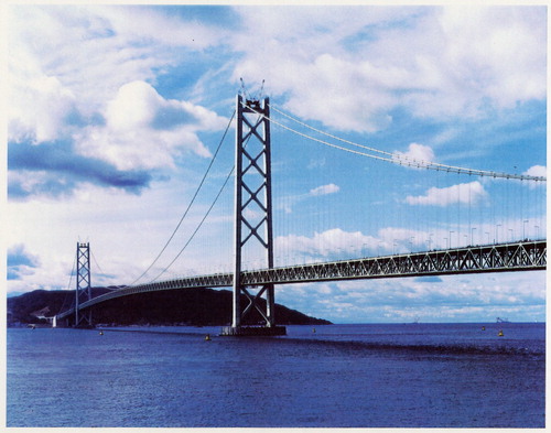
Nevertheless, some 50 million tonnes of cementite is produced annually within about 1.6 billion tonnes of steel, adding enormously to the quality of life. This is because it is hard at ambient temperature, as we shall see, due to its crystal structure that has a much lower symmetry than all the forms in which the iron occurs. Its metastability mostly does not matter over the time scale and conditions of normal life. The longest single-span suspension bridge in the world, the Akashi-Kaikyo Bridge, utilises exceptionally strong ropes to suspend the deck. The bridge connects Kobe with Awaji Island and has a span of 1.9 km between the towers. There is enough steel wire used in the bridge to circle the earth seven times, with the bridge being designed to withstand an earthquake of Richter 8.5 magnitude. The bridge represents a magnificient triumph of engineering and steel containing substantial quantities of cementite, without which the ropes would be nothing short of feeble ().
Figure 1. The Akashi-Kaikyo Bridge in Japan, the longest single-span suspension bridge, which relies on huge cables made from pearlitic steel. Photograph courtesy of Professor Nobutaka Yurioka.
In spite of its metastability, we shall see that cementite is found in meteorites that have cooled at a few degrees per million years, and within diamonds found deep in the bowels of the Earth. It perhaps has played a seminal role in the genesis of carbon nanotubes from gaseous reactions. There is fledgling work to indicate that nanoparticles of cementite may have a useful purpose in biomedicine for the site-specific delivery of healing drugs.
This is a review about cementite as a phase in its own right. How was its chemical composition established given that the nature of carbon inside steel could not have been understood in the very early days of metallography? In 1878, Müller [Citation1] dissolved some steel in dilute sulphuric acid to leave behind a black residue which when analysed contained 6.01–7.38 wt-% carbon. Müller referred to this as amorphous iron. Comprehensive experiments done independently by Abel around 1883 were published in 1885 in a report, on the state of carbon within steel [Citation2]. This confirmed ‘the correctness of the conclusions based on earlier experiments, that the carbon in cold-rollled steel exists in the form of a definite iron carbide, approximating the formula FeC or to a multiple of that formula’. In the same experiments, hardened steel (presumably martensitic) ‘appeared to have the effect of preventing or arresting the separation of carbon, as a definite carbide’.
The name has its origins in the theory of Osmond and Werth, in which the structure of solidified steel consists of a kind of cellular tissue, the iron constituting the nucleus and the carbide the envelope of the cellsFootnote1 [Citation3,Citation4]. The carbide was therefore envisioned to cement the iron.
In mineralogy, the carbide is known as cohenite (Fe,Ni,Co)C, after the German mineralogist Emil Cohen, who was investigating material of meteoric origin. The impact of carbon-containing meteorites with the moon is speculated to lead to a reduction of the iron-containing minerals on its surface; the resulting reaction with the carbonaceous gases generated by the impact produces cementite [Citation5]. Cementite is in fact of much wider interest than in metallurgy alone, within subjects spanning from astrophysics, planetary science, Lunar processes, and biomedicine to name but a few.
Cementite often is said to be metastable with respect to graphite. However, as shown in , pure cementite when allowed to coexist only with graphite, is stable in the presence of graphite, presumably because the iron does not dissolve in graphite. When ferrite on the other hand is allowed to coexist with cementite and graphite, the stable mixture at equilibrium becomes ferrite and graphite. These calculations are consistent with observations on carburised iron, where the cementite in contact with ferrite decomposes more rapidly to graphite during heat treatment, than cementite that is lodged within coke [Citation6]. Nanoparticles of cementite that are surrounded by a thin shell of carbon remain stable as cementite during heat treatment at 700C for 90 min at ambient pressure [Citation7]. This might contradict the observation of cementite, rather than graphite, in meteorites that are iron-rich. However, meteorites are created when under large pressures; cementite then becomes stable because there is a prominent reduction in molar volume (
%) when graphite changes into cementite [Citation8]. However, it is not clear whether the meteoric material is under high pressures during cooling through the temperatures where cementite precipitates (it would be necessary for the meteorite to have been enclosed within a much larger cosmic body). At the low pressures associated with the size of typical meteorites, the cementite should decompose during cooling, but it does not do so. Meteorites cool at extraordinarily slow rates, some 10 K per million years, so any crystal will tend to grow with a high state of perfection. In the absence of heterogeneous nucleation sites, the genesis of graphite would be retarded, leaving open the possibility that the cementite observed is in fact metastable, not stabilised by pressure [Citation9]. Cementite particles have also been found in deeply-mined diamonds observed at ambient pressure, that will have experienced some 50 GPa of pressure during their formation [Citation10]; this cementite is also likely to be metastable.
Figure 2. Phase diagram calculations or 100 kg total weight, using MTDATA [Citation11] and the SGTE thermodynamic database. (a) Fe–25C at.-%, permitting only cementite and graphite to coexist. (b) The average carbon concentration is reduced slightly to allow ferrite to appear, in which case the most stable mixture becomes that of ferrite and graphite.
![Figure 2. Phase diagram calculations or 100 kg total weight, using MTDATA [Citation11] and the SGTE thermodynamic database. (a) Fe–25C at.-%, permitting only cementite and graphite to coexist. (b) The average carbon concentration is reduced slightly to allow ferrite to appear, in which case the most stable mixture becomes that of ferrite and graphite.](/cms/asset/c8a13df6-43a9-4ed2-8547-16baea781322/yimr_a_1560984_f0002_oc.jpg)
2. Stoichiometry of cementite
The carbon atoms in cementite are located in interstitial sites [Citation12,Citation13]; any deficit from the 3:1 Fe:C atom ratio is attributed to interstitial vacancies that normally are occupied by carbon atoms, as inferred from lattice parameter changes [Citation14]. The specific volume of cementite that is in equilibrium with ferrite at ambient temperature is found to be greater than that calculated using its measured lattice parameters, indicating vacant carbon sites, i.e. a deviation from the stoichiometric composition [Citation15]. Similar conclusions have been reached by measuring phase fractions and lattice parameters in rapidly cooled Fe–C alloys containing large carbon concentrations [Citation16]. Indeed, the detailed changes in three lattice parameters of cementite quenched from different temperatures have been shown to be consistent qualitatively with corresponding parameters calculated using ab initio methods where carbon-specific sites are left unoccupied [Citation17].
(a) shows the thermodynamically assessed phase boundaries between cementite and ferrite (α) or austenite
. Cementite has traditionally been depicted as a line compound in phase diagram calculations, but it has been shown that a thermodynamic model that permits its free energy to vary in a manner consistent with experimental data ((b) [Citation18]), is able to reproduce the equilibrium
and
phase boundaries. The fact that ferrite can precipitate from cementite that was equilibrated at elevated temperatures, proves that there is an increase in the amount of carbon within cementite at low temperatures, [Citation19].
Figure 3. (a) The composition of cementite that is in equilibrium with austenite or with ferrite in an Fe–C alloy. The data are due to Leineweber et al. [Citation17], determined by measuring the lattice parameters of cementite following quenching from the appropriate temperature. (b) Free energy curve of cementite as a function of chemical composition (referred to γ-Fe and graphite). After Gohring et al. [Citation18].
![Figure 3. (a) The composition of cementite that is in equilibrium with austenite or with ferrite in an Fe–C alloy. The data are due to Leineweber et al. [Citation17], determined by measuring the lattice parameters of cementite following quenching from the appropriate temperature. (b) Free energy curve of cementite as a function of chemical composition (referred to γ-Fe and graphite). After Gohring et al. [Citation18].](/cms/asset/0da64ef8-d675-4dda-b794-f128a6acdd12/yimr_a_1560984_f0003_ob.jpg)
Figure 4. Precipitation of fine platelets of ferrite from cementite. Reproduced with permission of Taylor and Francis from [Citation19].
![Figure 4. Precipitation of fine platelets of ferrite from cementite. Reproduced with permission of Taylor and Francis from [Citation19].](/cms/asset/17de952b-6106-4bfd-8a0a-b8c80eb050da/yimr_a_1560984_f0004_ob.jpg)
Any deviations from stoichiometry must be small because as demonstrated by Cottrell [Citation20], the bond energy between a carbon atom and iron is greater than that between two iron atoms. Therefore, any deficit of carbon would lead to a reduction in cohesion. Any extra carbon beyond the 3:1 Fe:C ratio would need to be accommodated in less-favoured interstices within the cementite lattice. The nature and energetics of the different kinds of interstitial sites within the cementite structure are discussed later (Section 3.1).
Circumstances can be engineered to make the cementite deviate from the stoichiometric carbon concentration; the decarburisation of pure cementite [Citation21], which leads to changes in the volume of the unit cell and in the Curie temperature of cementite, is an example. The deviation tends to be small, typically FeC
with
. There are reports that very small particles of cementite in the structure of iron alloys studied by the atom probe technique exhibit deviations from stoichiometry, but these results should be treated with caution because at small size, the surface energy plays a role in determining the composition of the cementite in equilibrium with the surroundings.
The Curie temperature, , depends on the composition of cementite, Table , where the data represent the average compositions of samples synthesised using mixtures of iron and graphite powders by heating to 1110
C under a pressure of 1 GPa. It is noteworthy that the Curie measurements are due to cementite alone. There is a pressure dependence, with
reduced to below ambient temperature in stoichiometric cementite for pressures in excess of 6 GPa, whereas carbon-rich cementite remains ferromagnetic to higher pressures
GPa).
Table 1. Ambient pressure measurements of the Curie temperature of cementite as a function of its carbon concentration. Data from Walker et al. [Citation22], determined by making cementite as a part of a transformer. Choe [Citation23] reports a somewhat lower  of 167.6C determined using a superconducting quantum interference magnetometer for ambient pressure.
An interpretation [Citation24] of the change in magnetic properties as a function of pressure attributes the phenomenon to the volume-dependent two-state theory for the high magnetic moment to small-volume low moment transition. Using an X-ray technique and diamond anvil equipment, it has been determined experimentally that the loss of ferromagnetism occurs at about 10 GPa. The change in volume required to induce the magnetic transition is about 5% [Citation24,Citation25].
The atom probe permits the composition of cementite to be measured directly using time-of-flight mass spectroscopy. There are, nevertheless, difficulties in measuring the carbon concentration of cementite [Citation26]. It has not yet been possible to demonstrate small deviations from stoichiometry using such high-resolution methods. However, using conventional atom probe field ion microscopy, extremely small (4 nm) cementite particles in severely deformed mixtures of ferrite and cementite have been shown to contain only 16 at.-% of carbon, a concentration that recovers to the 25 at.-% when the mixture is annealed to reduce the defect density and coarsen the cementite [Citation27]. It is argued that the deformation introduces defects such as vacancies into the cementite, leading to the reduction in carbon concentration. However, it is important to note that the particles containing such a large deviation from stoichiometry were not proven to retain the orthorhombic crystal structure.
One study, based on neutron diffraction intensities measured over at temperatures ranging from ambient to 800C in a eutectoid steel, claims huge deviations of the carbon concentration from the stoichiometric ratio in undeformed cementite [Citation28]; the result is unlikely given the extensive experimental data that exist in the literature for the
composition of this kind of cementite. Zhukov and co-workers have claimed, on the basis of lattice parameter measurements or metallographic observations, that the temperature from which a cast iron is quenched can alter the stoichiometry of cementite, but the results do not account for the partitioning of other solutes between the cementite and other phases [Citation29,Citation30].
3. Crystal structure of cementite
Cementite has an orthorhombic unit cell and the common convention is to set the order of the lattice parameters as a = 0.50837 nm, b = 0.67475 nm and c = 0.45165 nm. There are 12 atoms of iron in the unit cell and 4 of carbon, as illustrated in . Four of the iron atoms are located on mirror planes, whereas the other eight are at general positions (point symmetry 1).
Figure 5. The crystal structure of cementite, consisting of 12 iron atoms (large) and 4 carbon atoms (small, hatched pattern). The fractional z coordinates of the atoms are marked. Notice that four of the iron atoms are located on mirror planes, whereas the others are at general locations where the only point symmetry is a monad. The pleated layers parallel to (100) are in stacking with carbon atoms occupying interstitial positions at the folds within the pleats, with all carbon atoms located on the mirror planes. There are four Fe
C formula units within a given cell.
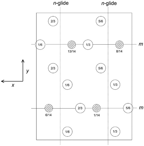
The lattice type is primitive . There are n-glide planes normal to the x-axis, at
and
involving translations of (
). There are mirror planes normal to the y-axis and a-glide planes normal to the z-axis, at heights
and
with fractional translations of
parallel to the x-axis. The space group symbol is therefore Pnma [Citation31]. Each Wyckoff position in this space group is labelled with a letter (Table ); thus, the eight iron atoms in general positions are labelled with the letter ‘d’, and the remaining four on mirror planes with the letter ‘c’; the number preceding the letter, for example, the ‘8’ in 8d, denotes the number of equivalent positions in the cell.Footnote2
Table 2. Wyckoff positions for space group Pnma.
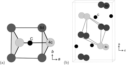
3.1. Types of interstitial sites
There are prismatic, octahedral and three kinds of tetrahedral interstices in the cementite unit cell; if the space within each is defined from the centre of the interstice to the boundary of the nearest iron atom, then the sizes are 0.71, 0.53, 0.34, 0.26 and 0.28 Å [Citation34]. The centres of the prismatic interstices lie on mirror planes so there are four per cell (4c, Table ) and they all are filled with carbon atoms in the stoichiometric form of cementite [Citation13]. The smaller octahedral interstices, of which there are four per cell (4a, Table ), are empty in pure cementite unless the carbon concentration exceeds 25 at.-%, and the tetrahedral interstices are too small to be occupied by carbon. When hydrogen enters the cementite lattice, it locates in the octahedral [Citation35] interstices because the prismatic ones are occupied by carbon ().
Figure 6. Two kinds of interstices in the cementite unit cell. (a) Prismatic. (b) Octahedral.
3.2. Structural defects and deformation
Given the orthorhombic structure, the elastic moduli of cementite vary with the direction within the crystal [Citation36]. The shear modulus is exceptionally small, some two times smaller than the corresponding term for aluminium. Nevertheless, the cementite has an exceptionally large ideal shear strength because elastic deformation reduces its symmetry from orthorhombic to monoclinic (space group
), with an accompanying increase in three-dimensional covalent bonding that stiffens the material [Citation37]. Thermal expansion is a function of crystallographic orientation; when cementite in its polycrystalline state is subjected to a change in temperature, reversible strains develop due to the pronounced anisotropy in thermal expansion coefficients leading to the broadening of X-ray diffraction peaks [Citation38,Citation39].
The experimentally observed slip systems in cementite include ,
,
,
and
[Citation40].Footnote3 Given the primitive nature of the lattice, it is assumed that the Burgers vectors of slip dislocations have magnitudes equal to the unit cell edges. These large vectors make slip difficult, making cementite a very hard phase at ambient temperatures.
The common slip system appears to be [Citation41]. The metal-metal bond is dominant between (010) planes so hardness depends on how solutes affect this bond strength [Citation42]. For example, nickel weakens the metal-metal bond and hence reduces the hardness of cementite [Citation43]. There may be other slip systems that operate when the cementite is forced to deform in a phase mixture such as pearlite [Citation44]. There is a limited continuity between the slip planes and slip directions of the two lattices [Citation45], and the Burgers vectors of dislocations in cementite are much larger than any in ferrite or austenite. This makes the transfer of slip across cementite difficult.
The stress relaxation of cementite at 1250C and 10 GPa pressure over a period of 8 h has also revealed dislocation glide on
with
slip reported to be the most frequent. The [100] dislocations were found to be dissociated into
[Citation46]. Ghaffarian et al. [Citation47] have conducted molecular dynamics simulations using of 16 grains of nanocrystalline cementite, but at the large strain rate of
, so their outcomes do not reproduce any of the observed experimental data other than to confirm the general expectation that grain boundary sliding may dominate deformation when the grain size is small.
Planar striations can sometimes be observed in cementite, particularly when it precipitates in the solid-state. Nishiyama et al. [Citation48] identified stacking faults on (010)θ using transmission electron microscopy, involving translations by vectors parallel to [100]θ that are not lattice vectors (). It is known that dislocations with the Burgers vector equal to the lattice vector [001]θ, which lie in (010) slip plane, are not in general dissociated except when they lie in the (130)θ plane [Citation49]. More complex faults occur on other planes. Cementite that grows at low temperatures can contain planar defects that are identified as two-layer thick regions of transition carbide χ-FeC
parallel to (010)θ; more complex faults occur due to the intercalation of iron into the cementite [Citation50]. Partial dislocations, whose motion would leave trailing faults, have been proposed to exist in cementite [Citation51]. Faults with varying levels of complexity have been hypothesised to exist in cementite but the experimental evidence for the actual displacements involved is limited.
Figure 7. Creation of a stacking fault on (010)θ by a partial displacement parallel to [100]θ that does not recreate the lattice. Carbon atoms have been omitted for clarity. (a) Unfaulted structure. (b) Faulted structure. Adapted from [Citation48].
![Figure 7. Creation of a stacking fault on (010)θ by a partial displacement parallel to [100]θ that does not recreate the lattice. Carbon atoms have been omitted for clarity. (a) Unfaulted structure. (b) Faulted structure. Adapted from [Citation48].](/cms/asset/28ca2db1-1bb1-48cc-8fc2-7deb267d544e/yimr_a_1560984_f0007_ob.jpg)
Point defects are known to exist in cementite in the form of vacancies in the carbon atom sites or as additional carbon atoms beyond the requirements of stoichiometry; the formation energy vacancies at the prismatic sites is very large, some 66–69 at 0 K [Citation18,Citation52]. Data from first-principles calculations for a variety of point defects in cementite are listed in Table .
Table 3. Calculated formation energies for point defects in cementite, referred to ferromagnetic bcc iron and diamond as the reference states. Data from the 128 atom simulations by Jiang et al. [Citation53]. The mole fraction of carbon in cementite is denoted x. For example, placing an iron atom in a prismatic interstice leads to a carbon concentration that is less than 25 at.-%.
Simulations show that cascades produced by irradiation can lead to vacancies in the iron sites, and anti-site defects where iron atoms lodge in interstitial positions [Citation54]. These point defect concentrations tend to be greater than those that occur in ferrite under the same conditions [Citation55]. Similar simulations suggest that the moduli of cementite are affected by irradiation, but the lattice parameters used do not seem to be correct [Citation56].
3.3. Hexagonal cementite
A hexagonal form of cementite (FeC) has been discussed in the literature, a form less stable than the orthorhombic variety. There is a dearth of experimental evidence and confusion about the actual structure and its chemical composition. Nagakura [Citation57] using electron diffraction concludes that the space group is
with lattice parameters a = 0.4767 nm and c = 0.4354 nm, as illustrated in ; although the structure selected is consistent with the composition Fe
C, the carbon concentration could not be measured with the techniques used.
Figure 8. Projection of the possible crystal structure of the hexagonal form of cementite, using the parameters and symmetry proposed by Nagakura [Citation57]. The fractional z-coordinates of atoms not located at z = 0,1 are marked. The carbon atoms (hatched) are located in a third of the octahedral interstices formed by the iron atoms.
![Figure 8. Projection of the possible crystal structure of the hexagonal form of cementite, using the parameters and symmetry proposed by Nagakura [Citation57]. The fractional z-coordinates of atoms not located at z = 0,1 are marked. The carbon atoms (hatched) are located in a third of the octahedral interstices formed by the iron atoms.](/cms/asset/7c8eb8a7-6c62-48f4-bbfd-623e2245357f/yimr_a_1560984_f0008_ob.jpg)
The original structure proposed by Jack [Citation58,Citation59] was rather different than that of Nagakura, with the iron atoms in a hexagonal close-packed arrangement and carbon atoms in octahedral interstitial sites, with chemical composition FeC, where x = 2.4−3 and lattice parameters a = 0.273 nm, c = 0.433 nm.
It is not clear whether a hexagonal form of cementite with a composition FeC actually exists. There are theoretical calculations associated with the phase, based on empirical methods or first principles [Citation60,Citation61]. Electron diffraction patterns from interplanetary dust particles have been identified with Nagakura's indexing of hexagonal cementite, although the chemical composition or stoichiometry of the particles remain undetermined and the same paper sometimes confuses the Nakagura and Jack structures in the discussion of the cementite [Citation62]. A recent study has claimed that a large fraction of the cementite present in a eutectic mixture with ferrite is hexagonal cementite, on the basis of electron back scattered diffraction [Citation63]. However, their independent X-ray diffraction data do not show two forms of cementite, only the orthorhombic variety.
4. Magnetic properties
Cementite at ambient pressure and room temperature is a metallic ferromagnet that becomes paramagnetic beyond the Curie temperature of 186
C (Table );
has been reported to be 208
C [Citation64] but based on changes in thermal expansivity that may not have sufficient resolution. The very first measurement was by Wologdine in 1909 [Citation65], in which particles of cementite suspended between magnetic poles were seen to collapse as the temperature was increased, giving
C. Smith in 1911 indicated changes in magnetometer readings due to cementite contained in steel to be between 180 and 250
C, claiming that actual Curie temperature to be around 240
C [Citation66]. Honda in 1915 put this value at 210
C [Citation67].
The calculated magnetisation of cementite as a function of temperature is illustrated in [Citation68], where the average magnetisation at 0 K is about 1.86 . There are a number of calculations of the local magnetic moments on the four iron atoms located on mirror planes (4c) and at the eight located at general positions (8d), giving estimates within the ranges 1.92–2.01 and 1.74–1.957
, respectively, [Citation68–71] at 0 K. The ranges quoted primarily arise because the estimation of the local magnetic moment depends on the size of the region (‘muffin tin’) over which the moment is calculated, and there may be differences in numerical accuracies of the methods used; the total magnetic moment of the unit cell which sums over the entire region is therefore essentially identical in the variety of calculations available [Citation72].
Figure 9. Calculated magnetisation of cementite as a function of temperature, after Dick et al. [Citation68].
![Figure 9. Calculated magnetisation of cementite as a function of temperature, after Dick et al. [Citation68].](/cms/asset/0cda20a3-0e90-4072-922d-f5cf551d129e/yimr_a_1560984_f0009_ob.jpg)
There is a transition from ferromagnetic to nonmagnetic states at 25 GPa pressure and 300 K [Citation73]. The term nonmagnetic is used here because it is not clear whether the magnetic collapse corresponds to a loss of spin correlation or to a transition from a high-spin to a low-spin state. There is a volume contraction of 2–3% following the transition from the ferromagnetic state. The structure, with its orthorhombic symmetry, is magnetically anisotropic, with [001]θ, [010]θ being the easiest and second easiest, and [100]θ the hardest magnetisation directions [Citation23,Citation74,Citation75]. The magnetocrystalline anisotropy energy is 334 [Citation75]. The dominant domain walls lie in the (001)θ plane, [Citation76]; Hillert and Lange first observed magnetic domains in cementite [Citation77].
Figure 10. Magnetic domain structure of cementite. Reprinted from [Citation76], with the permission of AIP Publishing.
![Figure 10. Magnetic domain structure of cementite. Reprinted from [Citation76], with the permission of AIP Publishing.](/cms/asset/c9d87f86-6766-445b-a773-b728745ebaff/yimr_a_1560984_f0010_ob.jpg)
Substitutional solutes such as nickel, chromium, manganese, etc. affect the magnetic properties of cementite. The addition of nickel reduces the saturation magnetisation simply because of the replacement of high magnetic moment iron atoms with low moment nickel atoms. These together with observations on other solutes such as Mn and Cr, on the saturation magnetisation, are consistent with the average alloy magnetic moment per atom to be expected from the Slater-Pauling curve. The alloying has only a minor effect on the intrinsic magnetic moment of the iron atoms [Citation78]. Alloying with manganese makes the cementite magnetically softer, i.e. reduces its coercivity [Citation79]. The influence of substitutional solutes on the magnetic moment of iron is, naturally, site-specific (Table ).
Table 4. Magnetic moments (in units of per iron atom) as a function of a silicon atom substituted into an 8d or 4c iron site. Data from Jang et al. [Citation71]. Similar site-specific data for chromium in cementite are available in Medvedeva et al. [Citation80].
The effect of manganese goes beyond the dilution of the magnetic moment per atom when manganese substitutes for iron [Citation81]. Calculations for show that at 0 K the spins on manganese atoms that locate on 8d positions adopt an antiferromagnetic alignment, whereas all Fe and Mn atoms at 4d positions have identical spins (). As a consequence, the net total magnetisation per unit cell decreases with an increase in manganese concentration. If the cell contains eight or more Mn atoms, then the 8d layer has a perfectly antiferromagnetic arrangement with the remaining atoms in the 4c positions in a ferromagnetic alignment [Citation81].
Figure 11. The orthorhombic unit cell with eight metal atoms in the 8d positions (circles), four in the 4c locations and four carbon atoms (small circles). The magnetic structures are from calculations representative of 0 K. (a) Ferromagnetic cementite of composition FeC, where all the metal atoms are iron. (b) Mn
C, where all the metal atoms are manganese. The 8d layers are perfectly antiferromagnetic, whereas the four atoms at 4c locations all have spins aligned; the Mn
C is therefore a ferrimagnet. Adapted from Appen et al. [Citation81].
![Figure 11. The orthorhombic unit cell with eight metal atoms in the 8d positions (circles), four in the 4c locations and four carbon atoms (small circles). The magnetic structures are from calculations representative of 0 K. (a) Ferromagnetic cementite of composition Fe3C, where all the metal atoms are iron. (b) Mn3C, where all the metal atoms are manganese. The 8d layers are perfectly antiferromagnetic, whereas the four atoms at 4c locations all have spins aligned; the Mn3C is therefore a ferrimagnet. Adapted from Appen et al. [Citation81].](/cms/asset/95b755c1-df59-40a8-8c5b-132f2dd3aaac/yimr_a_1560984_f0011_ob.jpg)
Cementite exhibits a magnetocaloric effect [Citation82]. During adiabatic demagnetisation, the alignment of magnetic spins decreases. Since the total entropy remains constant during the adiabatic conditions, the increase in magnetic entropy on the removal of the applied field is compensated for by a decrease in temperature. If demagnetisation occurs isothermally, then the change in magnetic entropy leads to a corresponding change in total entropy. Measurements indicate an adiabatic change in temperature of K during a field change of 2 T. When the magnetic field is changed from 0 to 20 T and an entropy change under isothermal conditions of 3
[Citation82].
There is a single report [Citation83] of two modifications of cementite, one ferromagnetic and the other paramagnetic, coexisting at ambient temperature. This conclusion was based on the interpretation of Mössbauer spectra. There has been no follow-up on this observation or any theoretical interpretation since the original publication.
5. Thermal properties
The average thermal expansion coefficient of polycrystalline cementite changes from to
as the sample is heated to beyond the Curie temperature, [Citation64].
Figure 12. The linear thermal expansion coefficient of polycrystalline cementite as a function of temperature and magnetic state. Adapted using data from Umemoto et al. [Citation64].
![Figure 12. The linear thermal expansion coefficient of polycrystalline cementite as a function of temperature and magnetic state. Adapted using data from Umemoto et al. [Citation64].](/cms/asset/b5deda3e-da90-4da0-9da8-a1d4a2dcda29/yimr_a_1560984_f0012_ob.jpg)
shows diffraction data [Citation84–86] for each of the lattice parameters of cementite as a function of temperature. The parameter a is most sensitive to the change from the ferromagnetic to paramagnetic state, with a contraction evident as the temperature is raised within the ferromagnetic range. An increase in the amplitude of thermal vibrations in an anharmonic interatomic potential causes expansion, but the spontaneous magnetisation leads to a contraction, and this latter effect dominates the a parameter below , leading to the observed Invar type effect, although it is known that the analogy with the Invar effect in austenite is tenuous. The orthorhombic structure is preserved through the transition at
. It is not clear why the a parameter is particularly affected by the magnetic transition.
Figure 13. Neutron and X-ray diffraction data on the three lattice parameters a, b and c of cementite as a function of temperature. Data from [Citation85] (small circles with error bars), [Citation84] (filled circles) and [Citation86] (crosses). The dashed line in each case identifies the Curie temperature. The calculated pressure dependencies of the lattice parameters are as follows [Citation87]: ,
and
Å, where the pressure P is in GPa.
![Figure 13. Neutron and X-ray diffraction data on the three lattice parameters a, b and c of cementite as a function of temperature. Data from [Citation85] (small circles with error bars), [Citation84] (filled circles) and [Citation86] (crosses). The dashed line in each case identifies the Curie temperature. The calculated pressure dependencies of the lattice parameters are as follows [Citation87]: Δa=0.0041×P, Δb=0.00578×P and Δc=0.00374×P Å, where the pressure P is in GPa.](/cms/asset/5c34a5dd-4708-4c9d-9c91-a57cd8c470aa/yimr_a_1560984_f0013_ob.jpg)
6. Surface energy
The anisotropy of the surface energy of cementite may have a role to play in its fracture, particularly at temperatures where its plasticity is limited. The energy cost is in the creation of two new surfaces. Cementite is found experimentally to cleave on the ,
, and
planes [Citation88]; this is inconsistent with the data presented in Table where the
plane has the highest surface energy when compared with
and
. It is speculated that there is additional work, for example, localised plasticity, associated with the process, even though cementite is brittle at ambient temperature.
Table 5. Calculated surface energies of cementite in a vacuum. A further broadly similar set of data calculated using interatomic potentials is available in Reference [Citation89] but the authors concerned did not express confidence in the relative values of the moduli.
7. Elastic properties of single crystals of cementite
First-principles calculations of the elastic moduli are presented in Table ; the anisotropy is illustrated on stereographic plots for cementite and for comparison, MnC which is isomorphous with Fe
C, together with a comparison with similar data for ferrite, in . A crystal subjected to an elastic strain is only stable if there is a resulting increase in its internal energy [Citation92]. For an orthorhombic crystal, this stability criterion manifests as follows [Citation93]:
(1)
(1) In a couple of cases,
has been found to be negative, implying that cementite at 0 K is mechanically unstable (Table ), [Citation61,Citation87,Citation94]. However, this contradicts experience, and cementite is obviously stable in practice, even at 4.2 K [Citation85]. This indicates that the calculations may not be correct. Other calculated data [Citation36] yield a positive
, which was revealed to be particularly sensitive to the structural relaxation permitted during the calculations, although it always remained positive. This study [Citation36] used a superior sampling of reciprocal space and cut-off energy (higher values give better convergence on properties but are computationally more expensive). First principles calculations of this kind are for 0 K, which may not be representative of the moduli at normal temperatures; given that
is sensitive to atomic positions, it would not be surprising if finite temperatures lead to large changes in this modulus. Experimental data determined under ambient conditions using nanoindentation indicate that the level of elastic anisotropy is in fact less than that evident from the first-principles calculations [Citation41] and that
is small but positive [Citation95].
Figure 14. Stereographic projections showing the variation of calculated single-crystal elastic moduli as a function of orientation, for the setting Pnma. (a) FeC [Citation96]. (b) Mn
C, using data from [Citation96] and lattice parameters from [Citation100]. (c) Corresponding data for body-centred cubic iron. Plots courtesy of Shaumik Lenka.
![Figure 14. Stereographic projections showing the variation of calculated single-crystal elastic moduli as a function of orientation, for the setting Pnma. (a) Fe3C [Citation96]. (b) Mn3C, using data from [Citation96] and lattice parameters from [Citation100]. (c) Corresponding data for body-centred cubic iron. Plots courtesy of Shaumik Lenka.](/cms/asset/2dd589d5-c520-472a-824d-98964d708a94/yimr_a_1560984_f0014_oc.jpg)
Table 6. Modulus data for cementite (space group Pnma) at 0 K and zero pressure unless otherwise indicated: the nine independent, calculated elastic stiffness constants (GPa) using the stress-strain method, for 0 K. represents the estimated change in the relevant stiffness component on heating from 0 to 400 K. The data for (FeX)C are specific to manganese atoms substituting for iron atoms that are not on mirror planes, for (XFe)C the atoms X are substituted into the eight general positions of iron.
Many of the first-principles calculations assume that the composition of cementite is exactly FeC whereas in practice, there may be deviations about stoichiometry [Citation17]. They seem to overestimate the pressure at which cementite loses ferromagnetism by an order of magnitude [Citation22]. Hydrostatic compression leads to an increase in stiffness, consistent with a corresponding decrease in the volume of the unit cell, .
Figure 15. Experimentally determined plot of pressure versus density for polycrystalline cementite. The gradient increases with density, indicating an increase in the bulk modulus with pressure. Data from Fiquet et al. [Citation101].
![Figure 15. Experimentally determined plot of pressure versus density for polycrystalline cementite. The gradient increases with density, indicating an increase in the bulk modulus with pressure. Data from Fiquet et al. [Citation101].](/cms/asset/b05434b7-7331-42d4-adde-8fceebbfced9/yimr_a_1560984_f0015_ob.jpg)
In some ingenious experiments, the elastic properties of single-crystals of cementite were measured for ambient temperature (Table ), [Citation102]. The measured moduli are less than those calculated, even though an increase in temperature stiffen the cementite [Citation98]. Koo et al. [Citation102] conducted similar measurements on single crystals of cementite which may have contained some manganese, estimated to be less than 0.5 wt-%. First principles calculations indicate that manganese increases the modulus of cementite (Table ) consistent with the data that GPa and
GPa.
Table 7. Comparison of the measured and calculated elastic moduli of pure Fe–C single-crystals of cementite. Data from Koo et al. [Citation102], rounded off to integers. The uncertainties represent scatter in experimental data. The calculated values are based on first-principles estimates due to Jiang et al. [Citation36].
8. Elastic properties of polycrystalline cementite
The pressure dependence of the bulk modulus of cementite is of importance in determining the characteristics of the phase at the core of the earth. Measurements have therefore been made using diamond anvil cells subjected to synchrotron X-rays to determine the pressure–volume relationship with the data fitted to an equation of state as follows [Citation103]: (2)
(2)
is the selected reference volume, and
,
and
are the pressure, isothermal bulk modulus and pressure dependence of that bulk modulus, all at the reference volume, respectively. The relationship between the bulk modulus and volume was also given in [Citation103, equation (1b)] but that equation seems to be dimensionally incorrect. Data corresponding to Equation (Equation2
(2)
(2) ) are as follows:
Table
The unmodified form of the Birch-Murnaghan equation is [Citation104,Citation106]:(3)
(3) where
Å3 [Citation104] and
are the volume and isothermal bulk modulus at 1 bar and 300 K, respectively, and
is the first pressure derivative of
at 300 K [Citation104]. With this equation of state, the measured data are in Table .
Table 8. Measured equation of state data [Citation73]. There are three sets of values stated for the paramagnetic state studies by Litasov et al. [Citation107] corresponding to different equations of state used to analyse the experimental data.
The data from first-principles calculations of single-crystal elasticity can be used to estimate the elastic properties of polycrystalline cementite by assuming uniform stress (Reuss) or uniform strain (Voigt) throughout the cementite [Citation109]:(4)
(4) where S represents a compliance, E, K and G are the Young's, bulk and shear moduli, ν is the Poisson's ratio and the subscripts ‘R’ and ‘V’ representing the Reuss and Voigt formulations; the absence of a subscript indicates an average of the Reuss and Voigt values. Using Jiang et al.'s single-crystal data (Table ) gives K = 227 GPa, G = 75 GPa, E = 203 GPa and
for zero Kelvin. The Young's modulus of pure polycrystalline cementite has been measured to be 196 GPa, but can increase to values as high as 245 GPa when alloyed with solutes such as chromium and manganese [Citation64]. Measurements on thin (210 nm), polycrystalline films of cementite indicate a Young's modulus of 177 GPa, which gives a shear modulus of 70 GPa assuming that the Poisson's ratio is 0.26 and isotropic elasticity [Citation110,Citation111]. The Poisson's ratio measured on samples of cementite containing 28% porosity has been reported to decrease almost linearly from 0.254 to 0.246 as the temperature is increased from 95 to 290 K [Citation112].
9. Preparation of cementite
Samples of bulk, pure cementite are difficult to prepare given that cementite in contact with iron is less stable than the corresponding equilibrium between graphite and ferrite. The largest samples have been manufactured by mechanical alloying in experiments by Umemoto et al. [Citation113]. Powders of iron and graphite in the correct stoichiometric ratio are milled together, resulting in a solid solution, as indicated by very broad X-ray diffraction peaks in locations typical of body-centred cubic iron. The mechanically alloyed powder was then spark plasma sintered under vacuum at 50 MPa pressure for 300 s at 1173 K, inducing the formation of cementite, (a) [Citation113]. The density achieved was 7.5
, which is less than the measured value for pure cementite of 7.662
[Citation114] indicating a degree of porosity in the sintered samples.
Figure 16. (a) A sample of cementite, courtesy of Professor Minoru Umemoto of Toyohashi University. (b) Reaction of 80 wt-% Fe and 20 wt-% graphite for 10 min at the temperatures and pressures indicated. Selected data from [Citation115].
![Figure 16. (a) A sample of cementite, courtesy of Professor Minoru Umemoto of Toyohashi University. (b) Reaction of 80 wt-% Fe and 20 wt-% graphite for 10 min at the temperatures and pressures indicated. Selected data from [Citation115].](/cms/asset/a4dc646f-70f2-4055-90f1-be901c9e2eac/yimr_a_1560984_f0016_oc.jpg)
The sintering step has been unnecessary in other work where cementite was obtained directly during the milling process [Citation116–118]. This might be explained by the fact that Umemoto et al. [Citation113] milled their powders for a much longer time. A comparison of the X-ray diffraction peaks obtained in the two studies is shown in . The broadening is caused by strain due primarily to dislocations locked within the powder, indicating a much larger defect density in the samples of the Umemoto study. Carbon prefers to be located at dislocations rather than in cementite [Citation119]; this explains the necessity for the sintering stage in the Umemoto study.
Figure 17. A comparison of the X-ray peaks from the experiments of Umemoto et al. [Citation113] and Joubouri et al. [Citation118] – the latter has been corrected to the Co K
wavelength to permit the comparison.
![Figure 17. A comparison of the {110}θ X-ray peaks from the experiments of Umemoto et al. [Citation113] and Joubouri et al. [Citation118] – the latter has been corrected to the Co Kα wavelength to permit the comparison.](/cms/asset/1331c780-fa76-4742-a305-37b0e0a47afc/yimr_a_1560984_f0017_ob.jpg)
It has been proposed, based on evidence from Mössbauer spectroscopy, that there are intermediate stages between the formation of the solid solution during milling, and that of cementite. The process may first involve transition carbides such as Hägg (FeC) and ϵ-carbide, followed by cementite [Citation120]. Cementite can be made directly from Hägg carbide through the reaction
[Citation121]. Alternatively, powdered cementite can be made by heating Hägg carbide, which is richer in carbon, in a nitrogen stream at 800
C for some 20 min [Citation122]. The resulting sample may contain traces of free iron and amorphous carbon. Cementite also forms when a mixture of iron and graphite heated under a pressure of less than 5 GPa at about 1000
C, (b) [Citation115]. Cementite powders have been made traditionally by electrochemical extraction from steel containing cementite [Citation123].
A clever method [Citation75] for fabricating a ‘single crystal’ of cementite is to incorporate electrolytically extracted cementite particles into a resin which then is subjected to a 10 Tesla magnetic field for some 24 h with the composite periodically rotated in the field to magnetically align the particles as the resin solidifies. This enabled the magnetocrystalline anisotropy of the cementite to be determined experimentally.
Iron can be converted into cementite by exposing it to a carburising gas mixture, if the activity of carbon relative to graphite is maintained at greater than one. Graphite is deposited preferentially unless the surface of the iron is contaminated with blocking atoms such as sulphur, in which case cementite is precipitated [Citation124]. It has been demonstrated that cementite can be made by carburising magnetite (FeO
) at 1073 K with carbon monoxide [Citation125]. It is speculated that cementite produced in this manner could be used in an electrical arc furnace to produce iron while at the same time reducing carbon dioxide emissions.
Nanoparticles of cementite can be prepared by the thermal decomposition of Fe(CO) (iron pentacarbonyl). These fine particles may be of use in biomedicine for delivery of drugs to specific locations within the body, with the localisation achieved by an external magnetic field [Citation126]. Elemental iron particles have been proposed for this purpose but they tend to oxidise [Citation127]. Cementite is more corrosion and oxidation resistant,Footnote4 while retaining sufficient ferromagnetism to implement the delivery mechanism. Dispersions of polymer coated cementite nanoparticles have been manufactured by subjecting a gaseous mixture of
to a continuous wave
laser pyrolysis [Citation129], .
Figure 18. Cementite nanoparticles produced using laser pyrolysis of a gaseous mixture. Reproduced from Morjan et al. [Citation129] with permission from Elsevier.
![Figure 18. Cementite nanoparticles produced using laser pyrolysis of a gaseous mixture. Reproduced from Morjan et al. [Citation129] with permission from Elsevier.](/cms/asset/8fbf3383-e84a-4875-9edf-c0ab9f00c0e5/yimr_a_1560984_f0018_ob.jpg)
Cementite powder containing pores about 20 nm in size from an aqueous mixture of iron chloride, colloidal silica and 4,5-dicyanoimidalzole. The dicyanoimidalzole is the source of carbon when the mixture is heated to 700C to produce the powder of cementite which also contains amorphous silica. The silica is then removed by solution in sodium hydroxide, leaving the porous cementite with a high specific surface area of 415 m2 g−1. This cementite was demonstrated to be catalytically active in the decomposition of ammonia into a mixture of hydrogen and nitrogen. Cementite apparently has greater stability under harsh conditions than metallic iron, and is safer with respect to the danger of explosions associated with fine metallic powders [Citation130]. Cementite has in fact been shown to exhibit catalytic activity even in the classical Firscher-Torpsch process for converting gaseous components into hydrocarbon liquids [Citation131].
10. Electrical conductivity
Electrical conductivity data from first-principles calculations, measurements made on cementite-containing microstructures and on pure cementite are compiled in . The large difference between the calculated value and measurements is attributed to the fact that a real material is likely to contain defects that reduce electrical conductivity. The Umemoto data on pure, bulk cementite are from its polycrystalline state [Citation113]; it is not clear why those due to Lee and Simkovich [Citation132] correspond to a much lower conductivity, although it is noted that the sample preparation methods for the two studies are different. The fact that the electrical resistance (i.e. reciprocal of conductivity) increases with temperature confirms that cementite is metallic rather than a semiconductor [Citation132].
Figure 19. The data on pure cementite are from [Citation113,Citation132], the calculated datum from [Citation69] and the measurements of mixed microstructures, extrapolated to single-phase cementite, from [Citation133].
![Figure 19. The data on pure cementite are from [Citation113,Citation132], the calculated datum from [Citation69] and the measurements of mixed microstructures, extrapolated to single-phase cementite, from [Citation133].](/cms/asset/59075428-0ca8-4796-9654-6e362eadc710/yimr_a_1560984_f0019_oc.jpg)
11. Strength, ductility, toughness and wear
The ideal strength of cementite, i.e. in the absence of dislocations, can be estimated using first principles methods. An increment of strain is applied to a unit cell which then is allowed to relax both in shape and atomic positions, so that only the stress along the applied direction is non-zero. The stress corresponds to the derivative of the free energy with respect to strain. The maximum in strength is given by an instability when an inflexion occurs in the free energy versus strain curve. Calculated data using this method are illustrated in ; as expected, there is considerable anisotropy in properties.
Figure 20. Calculated ideal values of ultimate strength at corresponding engineering strains for perfect crystals of cementite. (a) Tensile deformation along crystallographic axes parallel to the cell axes. (b) Shears on the planes and directions indicated. Uniform colour indicates data from Garvik et al. [Citation51] whereas the cross-hatched bars are from Jiang and Srinivasan [Citation37].
![Figure 20. Calculated ideal values of ultimate strength at corresponding engineering strains for perfect crystals of cementite. (a) Tensile deformation along crystallographic axes parallel to the cell axes. (b) Shears on the planes and directions indicated. Uniform colour indicates data from Garvik et al. [Citation51] whereas the cross-hatched bars are from Jiang and Srinivasan [Citation37].](/cms/asset/cd262300-786f-4e59-8d62-34b86122700f/yimr_a_1560984_f0020_oc.jpg)
Early experiments designed to measure the strength of cementite were confined to small samples extracted from high carbon steel. Ribbon-like samples of cementite 1–2 μm thick and 1 mm long when tested by bending gave strength estimates in the range 4.6–8 GPa [Citation134]. Experiments on 2.5μm thick films of cementite with a grain size of about 50 nm, on samples prepared using plasma vapour deposition, revealed a microhardness of about 1230 HV at ambient temperature, decreasing to about 650 HV at 673 K [Citation110]. Young's moduli measured on polycrystalline thin films range from 160–180 GPa. More comprehensive hardness data are shown in ; it is clear that hardness measurements from bulk cementite samples prepared by mechanical alloying and spark plasma sintering, are systematically lower than some measurements made on eutectic cementite within cast iron, or prepared by plasma synthesis. In the latter case the grain size can be as small as 50 nm which may add some strengthening, but the intrinsic resistance to plastic deformation due to the Peierls barrier is likely to be a much greater contribution. The sintered samples all contain some porosity which can reduce the strength [Citation135], however, the data from Kagawa and Okamoto [Citation136] from cementite in cast iron, are remarkably consistent with those on bulk cementite (). There is an intriguing study by Drapkin et al. [Citation137] where primary cementite was found to be much harder (≈ 1070–1350 HV) than eutectic cementite (≈ 740–960 HV) in cast iron; these data are unexplained.
Figure 21. (a) The Vickers hardness of cementite. The data for pure cementite, filled circles and crosses, are from Umemoto et al. [Citation113] and Kagawa & Okamoto [Citation136]. Umemoto's data are from bulk cementite, Kagawa's from cementite within cast iron. Those for cementite containing chromium at the concentrations are from Zheng et al. [Citation138]. The curves represent measurements on cementite in cast iron, alloyed with an unspecified amount of chromium or boron [Citation136]. The hardness values may be underestimates due to some porosity in the samples. (b) Ambient temperature microhardness data for cementite within a cast iron microstructure [Citation139,Citation140] and from plasma deposited FeC [Citation110]. The chemical compositions indicated are in wt-% and represent measurements on cementite alone.
![Figure 21. (a) The Vickers hardness of cementite. The data for pure cementite, filled circles and crosses, are from Umemoto et al. [Citation113] and Kagawa & Okamoto [Citation136]. Umemoto's data are from bulk cementite, Kagawa's from cementite within cast iron. Those for cementite containing chromium at the concentrations are from Zheng et al. [Citation138]. The curves represent measurements on cementite in cast iron, alloyed with an unspecified amount of chromium or boron [Citation136]. The hardness values may be underestimates due to some porosity in the samples. (b) Ambient temperature microhardness data for cementite within a cast iron microstructure [Citation139,Citation140] and from plasma deposited Fe3C [Citation110]. The chemical compositions indicated are in wt-% and represent measurements on cementite alone.](/cms/asset/2552437f-4d9a-4e99-8d6d-bdbdc95acd6b/yimr_a_1560984_f0021_ob.jpg)
Indentation fracture toughness values have been reported for cementite in alloyed cast-iron, i.e. embedded single-crystals of cementite, Table [Citation141]. The absolute values of toughness are really quite small, but bearing that in mind, vanadium seems to enhance toughness, possibly because it softens the cementite, although the mechanism involved is not known. The single-crystal mechanical data should vary with the crystallographic orientation; the scatter observed in nanoindentation evaluations of hardness and modulus [Citation142] may be a consequence of the neglect of orientation effects.
Table 9. Indentation fracture toughness of cementite present in cast irons at ambient temperature [Citation141]. The hardness data measurements include elastic strains and hence will be underestimated. The chemical compositions represent energy-dispersive X-ray analysis data of the cementite phase alone. The indentation toughness of cementite of unspecified composition in a nickel-containing cast iron has been reported to be 4.09 MPa m although the reported hardness of 1340 HV is quite large [Citation140].
Cementite in steels is often touted as helping resist wear in a variety of applications such as bearings and rails [Citation143–145] where the carbide is present as a minor phase embedded within a matrix of ferrite or martensite. shows the reciprocal of the wear rate for a variety of samples of ferrite containing different amounts of cementite [Citation146], including data for pure cementite made by mechanical alloying followed by plasma sintering. The reciprocal wear rate is given by PL/V, where P is the applied pressure, and V is the volume of material lost as the pin of the sample material rubs against a rotating alumina disc over a distance L.
Figure 22. Data from the abrasion of a pin made out of the material of interest, against an alumina disc. After Sasaki et al. [Citation146].
![Figure 22. Data from the abrasion of a pin made out of the material of interest, against an alumina disc. After Sasaki et al. [Citation146].](/cms/asset/2ef5d572-e192-492f-926b-17567cb42f2d/yimr_a_1560984_f0022_ob.jpg)
As concluded by Sasaki et al. [Citation146], the data show that at low pressures, the wear rate decreases as the amount of cementite in the sample increases, as long as the abrasion process does not lead to the formation of large brittle chips of cementite. At the high pressure, the brittle chip formation makes the pure cementite wear more rapidly than at low pressures.
12. Substitutional solutes
Alloying cementite with manganese reduces the rate at which it might decompose into graphite [Citation147]; it has been known for some time that cementite becomes more stable when it ‘unites with manganese’, sometimes resulting in the growth of robust single-crystals known as Speigeleisenkristall [Citation148]. (a) shows that the addition of manganese permits cementite to co-exist with graphite and ferrite, whereas in the same circumstances, a Fe–25C at.-% steel would, at equilibrium, consist only of a mixture of ferrite and graphite. The cementite in the Fe–C–Mn alloy contains manganese, the equilibrium composition of which at low temperatures is more akin to MnC than Fe
C ((b)).
Figure 23. Phase diagram calculations for 100 kg total weight, using MTDATA [Citation11] and the SGTE thermodynamic database. Fe–25C–4.08Mn at.-%, permitting cementite, graphite and ferrite to co-exist. (a) Equilibrium phase mixture as a function of temperature. (b) The equilibrium manganese concentration in cementite for the calculations presented in (a).
![Figure 23. Phase diagram calculations for 100 kg total weight, using MTDATA [Citation11] and the SGTE thermodynamic database. Fe–25C–4.08Mn at.-%, permitting cementite, graphite and ferrite to co-exist. (a) Equilibrium phase mixture as a function of temperature. (b) The equilibrium manganese concentration in cementite for the calculations presented in (a).](/cms/asset/a507d73f-169a-4c88-a208-698bcf5b0c12/yimr_a_1560984_f0023_oc.jpg)
Chromium hardens cementite, presumably by solid solution strengthening; shows that the effect is not large. Therefore, the effect of chromium additions on the wear resistance of cementite is also minimal, when the comparison is limited to data for single-phase cementite (i.e. neglecting samples with Cr wt-% in [Citation149,Citation150]).
The magnetic properties are affected in line with expectations, i.e. substituting an atom with a lower magnetic moment reduces the saturation magnetisation [Citation78,Citation151]. Iron atoms in cementite have local magnetic moments of 1.97 or 1.88
per atom, depending on whether they are located on the mirror or general positions [Citation152]; the corresponding values for manganese and nickel are about 0.8 and 0.6
, respectively, when substituted into the mirror sites. The addition of nickel therefore reduces the saturation magnetisation of the alloyed cementite, but the Curie temperature, which depends on the coupling between the magnetic ions, increases [Citation153]. The experiments on nickel-alloying of cementite are limited because the cementite tends to be unstable when nickel is forced into its lattice by mechanical alloying. During mechanical alloying of the stoichiometric mixtures, followed by heat treatment, an amorphous phase forms first, followed by the crystallisation of nickel-rich cementite and then the decomposition of the cementite [Citation154]. These observations are consistent with first-principles calculations that show that the substitution of nickel (or cobalt) make the cementite less stable with respect to a mixture of α-iron and graphite [Citation155].
There are circumstances where nickel-containing cementite has a favourable free energy of formation [Citation156]. (Fe,Ni)C is in fact stable to decomposition at 650
C over a range 10–50 at.-% Ni when the activity of carbon (
) in the gas with which the carbide is in contact is less than one (). It is claimed that (Fe,Ni)
C was detected by metallography and X-ray structure analysis, but it is not clear how these techniques reveal the chemical composition of the cementite [Citation156].
Figure 24. The free energy of formation associated with the reaction occurring at 650
C, as a function of the manganese or nickel concentrations. Adapted from Grabke et al. [Citation156].
![Figure 24. The free energy of formation associated with the reaction M+13C→M3C occurring at 650∘C, as a function of the manganese or nickel concentrations. Adapted from Grabke et al. [Citation156].](/cms/asset/adbb302a-a2d9-4721-bdca-b581dd00b086/yimr_a_1560984_f0024_ob.jpg)
Chromium has a strong affinity for carbon and hence when alloyed in cementite, makes the latter more stable with the free energy of formation decreasing systematically with concentration [Citation80,Citation157]. Zhou et al. [Citation158] have published data for chromium in cementite showing similar trends although the absolute values of formation energy are much greater, even for pure cementite. Manganese too is a carbide former, and once some complex magnetic effects (Section 4) are accounted for, leads to a thermodynamically more stable cementite. A compilation of data on a variety of solutes affecting the formation energy of cementite at 0 K are presented in . There is a significant variation in for pure cementite; the single point by Dick et al. [Citation68] is likely to be the most accurate since the graphite free energy is directly calculated rather than offset from diamond, although it is noted the van der Waals forces are neglected. The data for nickel and cobalt may be uncertain because Wang and Yan obtained
to be negative, in contradiction to both experimental and other theory-based data, and their paper does not give details of the reference states used. The indications are that scandium, titanium, vanadium, zirconium, and niobium substitutions into cementite make it more stable relative to its pure form [Citation159], but their efficacy in this context may be compromised by the limits of solubility or the tendency to form other carbides.
Figure 25. The calculated formation energy of cementite for the reaction
, where ‘M’ stands for a metal atom other than iron. The data for Cr-alloyed cementite (filled circles) are from Konyaeva and Medvedeva [Citation157], the manganese data from Appen et al. [Citation81], silicon data from Jang et al. [Citation71], for Ni and Co from Wang and Yang [Citation155], and the unfilled square is from Hallstedt et al. [Citation172]. The pure Fe
C data from Wang and Yang are not included since they predict a negative formation energy which is unlikely to be correct. Note that the energies depend slightly on the location of the substituted metal atom within the iron sub-lattice of the unit cell; details can be found in the individual publications.
![Figure 25. The calculated formation energy ΔF of cementite for the reaction {FFe3(1−x)M3xC−[3(1−x)FFe+3xM+Fgraphite]}/4, where ‘M’ stands for a metal atom other than iron. The data for Cr-alloyed cementite (filled circles) are from Konyaeva and Medvedeva [Citation157], the manganese data from Appen et al. [Citation81], silicon data from Jang et al. [Citation71], for Ni and Co from Wang and Yang [Citation155], and the unfilled square is from Hallstedt et al. [Citation172]. The pure Fe3C data from Wang and Yang are not included since they predict a negative formation energy which is unlikely to be correct. Note that the energies depend slightly on the location of the substituted metal atom within the iron sub-lattice of the unit cell; details can be found in the individual publications.](/cms/asset/5fa1f2b7-76ef-409e-be4a-f42d6f55ce9e/yimr_a_1560984_f0025_ob.jpg)
shows that silicon reduces the stability of cementite, a fact that is of considerable technological significance. It often is added to steel to suppress cementite while ensuring that the concentration is small enough that graphite does not form during the fabrication or use of the alloy [Citation160]. If cementite is suppressed, then any carbon partitioned due to ferrite formation ends up in the austenite, thus permitting it to be retained and enhance ductility and toughness. The influence of silicon on the precipitation of cementite is substantially greater when the matrix phase is supersaturated austenite, because the driving force for precipitation from supersaturated ferrite is much greater [Citation161]. The effect of silicon on cementite has been exploited for many decades in the design of steel microstructures [Citation162–170]. A detailed review, covering both steels and cast irons, can be found in [Citation171].
Boron, which is a larger atom than carbon but much smaller than iron, lodges within the prismatic interstices when it substitutes for carbon, thereby causing the volume of the unit cell to increase (); this location is consistent with the lack of change in the relative intensities of the X-ray diffraction peaks when pure cementite and that containing boron are compared [Citation173]. shows that large concentrations of boron can be introduced into cementite without changing its orthorhombic symmetry. The saturation magnetisation increases with the boron concentration, as does the Curie temperature which reaches 578C for a boron concentration of 5.2 wt-% [Citation173]. Perhaps because boron is a larger atom than carbon is the reason why it hardens cementite (). Borocementite can be induced by the diffusion of boron into the surface regions of cast irons [Citation174].
Figure 26. The lattice parameters of FeC and Fe
(B,C) as boron substitutes for carbon in the cementite unit cell. Adapted from Nicholson [Citation173].
![Figure 26. The lattice parameters of Fe3C and Fe3(B,C) as boron substitutes for carbon in the cementite unit cell. Adapted from Nicholson [Citation173].](/cms/asset/50228269-aa09-4fe9-818c-21421b7334b0/yimr_a_1560984_f0026_ob.jpg)
Helium atoms have closed 1s electron shells and hence interact repulsively in compression. When in cementite, the He will therefore tend to locate in the largest available spaces. Calculations indicate that it prefers to substitute for the iron rather than carbon atoms in cementite; the energy needed to substitute C, Fe and Fe
are 5.07, 3.34 and 3.52 eV, respectively [Citation175]. The same analysis suggests that the energy of formation of an iron vacancy in ferrite is greater than in cementite, so it is postulated that cementite should have a larger solubility for helium than ferrite. This may be of relevance when considering the swelling of steels by irradiation-induced helium bubble formation. In contrast, the most stable location for a hydrogen atom is an octahedral interstice, surrounded by six iron atoms, and that location has a lower energy than the corresponding interstice in ferrite [Citation176].
Changes in the lattice parameters of cementite have been determined experimentally as a function of the substitution of atoms on to the iron sites, Table [Citation177].
Table 10. Change in the lattice parameters of cementite (Pnma) as a function of the concentration in wt-%. The coefficients are derived from the work of Kagawa and Okamoto [Citation177].
12.1. Precipitation within cementite
The are no data on the solubility of copper in cementite; the usual phase diagram calculation packages indicate zero solubility, but this may simply be a reflection of the absence of appropriate thermodynamic data as inputs. There are now observations showing the precipitation of copper or copper-rich precipitates within cementite [Citation178], as opposed to precipitation at the interface during the cementite growth process [Citation179–181]. When precipitation occurs from supersaturated cementite, the implication is that excess solute is trapped within the cementite as it grows at large driving forces and low temperatures. This is rather like the trapping of silicon in cementite that forms at low temperatures [Citation71].
13. Thermodynamic properties
There are significant calculations of the heat capacity of cementite, using a combination of density functional theory and quantum Monte Carlo methods [Citation68]. These permit the individual contributions of phonon, electronic and magnetic components, with the total heat capacity in good agreement with thermodynamic assessments based on the CALPHAD method [Citation172]. The calculated values of the different components are illustrated in . Polynomial functions describing the free energy of cementite as a function of temperature have been derived by Hallstedt et al. [Citation172]. CALPHAD type data on cementite are widely available in the literature so are not reproduced here, other than in context where they add to insight or interpretation.
Figure 27. The calculated components of the heat capacity of cementite as a function of temperature at zero pressure; adapted from Dick et al. [Citation68].
![Figure 27. The calculated components of the heat capacity of cementite as a function of temperature at zero pressure; adapted from Dick et al. [Citation68].](/cms/asset/ac7a1f16-085c-4885-a310-9a8e8e0181d1/yimr_a_1560984_f0027_ob.jpg)
13.1. Stability and graphitisation
It has been known for some time [Citation182–184] that cementite is metastable with respect to the equilibrium between graphite and α-iron for all temperatures below the eutectoid in the iron-carbon binary phase diagram. Graphite and γ-iron saturated with graphite form a more stable mixture than cementite and γ-iron for higher temperatures. On the other hand, if cementite and α-iron can somehow coexist at temperatures above the Fe–C eutectoid, then free energy of formation data indicate that the mixture would be stable relative to α-iron+graphite, .
Figure 28. The formation energy of cementite for the reaction
. Data from CALPHAD assessment by Hallstedt et al. [Citation172]. A negative value implies that cementite becomes stable relative to the mixture of α and graphite.
![Figure 28. The formation energy ΔF of cementite for the reaction FFe3C−[3FFe+Fgraphite]/4. Data from CALPHAD assessment by Hallstedt et al. [Citation172]. A negative value implies that cementite becomes stable relative to the mixture of α and graphite.](/cms/asset/f00046d9-fb0a-48e9-a6c3-e08c1d09a5b8/yimr_a_1560984_f0028_ob.jpg)
The data presented in are essentially consistent with first principles calculations as far as the temperature dependence of is concerned, although the absolute values do not seem to compare well with thermodynamic data [Citation68]. Nevertheless, the cementite is predicted correctly to be metastable at 0 K, as long as the ground state energy of graphite is calculated rather than an estimation based on a shift from that of diamond [Citation68]. There exists a contradictory first-principles calculation [Citation155] that suggests
at 0 K, but there are insufficient details presented about how the ground state energy of graphite has been introduced.
Cementite presumably is easier to nucleate in the solid-state than graphite, hence its ubiquitous in its metastable form. One consequence is the phenomenon of metal dusting, associated with the formation of cementite due to the desorption of gases such as CO on the steel surface at an elevated temperature (400–800C) when the activity of carbon in the gas is sufficiently large [Citation156]. The oxygen partial pressure should be low enough to ensure that oxide formation does not become the dominant degradation mechanism. The cementite then decomposes into fine particles of iron and graphite, i.e. the dust. An addition of a small amount of hydrogen sulphide to the carburising gas leads to the adsorption of a monolayer of sulphur which helps retard its decomposition into graphite and iron [Citation185].
The formation of graphite leads to a large expansion in volume:where
is the volume of cementite. Therefore, unless voids are associated with cementite, it would be necessary for iron to diffuse in order to accommodate the growing graphite [Citation186]. Phosphorus and sulphur retard the process of graphitisation by segregation to any void surfaces, or possibly to ferrite-cementite interfaces.
Samples of cementite have been prepared by the reaction of FeO
with a mixture of 10% CO
–H
[Citation187] for the purposes of thermal stability assessments. The samples had an average carbon concentration of less than the stoichiometric proportion, so probably contained some iron. They tended to decompose into mixtures of carbon and iron when heated in pure argon at temperatures in the range 800–1100 K for periods of 10–60 min. As noted previously (Section 1), cementite that is in contact with iron decomposes more rapidly than when the cementite is isolated within a surrounding of carbon [Citation6,Citation7]. The decomposition of carbon-rich gases can be catalysed on iron particles, leading first to the conversion of the iron particles into cementite, which then decomposes into a mixture of carbon nanotubes and iron particles which may become embedded within the tubes [Citation188].
Cementite can be synthesised by gas () carburising iron-oxides at about 750
C. shows the thermal stability of such cementite in the form of time–temperature–transformation curves, when the carbide is reheated to a variety of temperatures. The rate at which the cementite decomposes is a lot slower when it is made from titanomagnetite; this was attributed to titanium dissolved in the cementite which makes it more stable to decomposition when compared against the binary cementite generated from haematite [Citation189]. A difficulty with this interpretation is that phase diagram calculations using the CALPHAD method indicate that there is no solubility of titanium in cementite [Citation190]; the titanium is more likely to be dissolved in the residual iron reported by Longbottom et al. [Citation189]. However, the same calculations show that when pure cementite is in equilibrium with iron-containing dissolved titanium, the cementite becomes stable to the formation of graphite.
Figure 29. Time, temperature and 50% transformation diagrams for the decomposition of cementite into elemental iron and carbon. In one case, the cementite is made by carburising haematite ore (FeO
), and in the other by similarly carburising titanomagnetite (Fe
Ti
O
). Selected data from Longbottom et al. [Citation189].
![Figure 29. Time, temperature and 50% transformation diagrams for the decomposition of cementite into elemental iron and carbon. In one case, the cementite is made by carburising haematite ore (Fe2O3), and in the other by similarly carburising titanomagnetite (Fe(1−x)TixO4). Selected data from Longbottom et al. [Citation189].](/cms/asset/156166f8-ae96-44f8-98f1-8ce7674c5428/yimr_a_1560984_f0029_ob.jpg)
Some calculations indicate that the orthorhombic η–FeC, monoclinic χ–Fe
C
and cubic Fe
C
are all thermodynamically more stable than cementite at zero Kelvin [Citation191]. A temperature dependence calculated for cementite to include lattice vibrations and magnetic contributions for the cementite and η indicated that the former becomes more stable when precipitation occurs below 330 K. Similar estimates were not made for Fe
C
and χ-carbide. In practice, kinetic factors such as the activation energy for nucleation, which is a sensitive function of interfacial energy, will play a role in the sequence of precipitation. Other solutes commonly present in steel may alter these considerations. After all, transition carbides of iron often precede cementite during the temperature of martensite or the formation of bainite at temperatures well above 330 K.
14. Cementite precipitation in metallic glass
Amorphous alloys of iron precipitate cementite when their carbon concentration is sufficiently large; it is difficult to be specific because there is no phase diagram relating to the equilibrium between cementite and the glassy alloy or even whether an equilibrium mixture of glass and cementite is possible. shows cementite and ferrite obtained by the devitrification of a binary glassy-steel 500 nm thick film during heat treatment at just 300C. It is not clear why the cementite is heavily faulted but its shape indicates that the growth process is reconstructive in nature. This would require the diffusion of iron atoms, and indeed, the rate of transformation is found to be slower than expected from the diffusion of carbon alone [Citation192].
Figure 30. Cementite (majority phase, containing planar faults) and equiaxed ferrite, crystallised from metallic glass films of composition Fe–13.6C at.-% by heat treatment at 300C for 3 h. Reproduced from Fillon et al. [Citation192] with permission from Elsevier.
![Figure 30. Cementite (majority phase, containing planar faults) and equiaxed ferrite, crystallised from metallic glass films of composition Fe–13.6C at.-% by heat treatment at 300∘C for 3 h. Reproduced from Fillon et al. [Citation192] with permission from Elsevier.](/cms/asset/91253181-d9ae-4aa3-9176-6b8d607292d1/yimr_a_1560984_f0030_ob.jpg)
Metallic glasses have a larger free volume than supercooled liquid because they essentially become configurationally frozen once below the glass-transition temperature. It is expected therefore that diffusion coefficients will be greater than in the crystalline version of the material. The measurement of diffusion coefficients is complicated by the fact that the glass will undergo structural changes such as relaxation and ultimately, devitrification, when measurements are conducted. Experiments on the diffusion of iron in a variety of metallic glasses in their relaxed condition, show that there is indeed an enhanced diffusivity in the glassy state (, [Citation193]).
Figure 31. 59Fe tracer diffusion coefficients in Fe–Zr and Fe–B glassy metals in the relaxed state. Self-diffusion data for iron in ferrite are included from [Citation194,Citation195], for comparison purposes. Selected data on the amorphous alloys from Horvath et al. [Citation193].
![Figure 31. 59Fe tracer diffusion coefficients in Fe–Zr and Fe–B glassy metals in the relaxed state. Self-diffusion data for iron in ferrite are included from [Citation194,Citation195], for comparison purposes. Selected data on the amorphous alloys from Horvath et al. [Citation193].](/cms/asset/7d7713c2-b772-4b0b-8c2c-355679ed21ae/yimr_a_1560984_f0031_ob.jpg)
15. Carbon nanotubes – role of cementite
Carbon nanotube formation from gaseous hydrocarbons is catalysed by fine particles of transition metals, particularly iron. Bulky iron or thin films of iron are not as effective as dispersed fine particles [Citation196]; this is because flat surfaces do not form good templates for the growth of tubes, and indeed, the size of catalyst particles correlates with the diameters of the nanotubes generated [e.g. [Citation197]].
Iron does catalyse the breakdown of hydrocarbons in appropriate circumstances, but there has been discussion [reviewed in Section 5.1.3, [Citation198]] about whether it is the iron particles or the cementite particles that form subsequently, that induce the nucleation and growth of multiwalled or single-walled carbon nanotubes. Environmental transmission electron microscopy has provided clear evidence for ‘graphitic networks’ first forming on cementite particles, followed by the genesis of carbon nanotube growth [Citation199,Citation200]. The process of carbon depositing on the cementite particle is not uniform, so carbon diffuses through the cementite from the graphite-rich region to that which is not coated, leading to the expulsion of carbon filaments [Citation196].
Not everyone accepts these conclusions about the role of cementite; Tessonnier et al. [Citation201] comment on electron beam-induced artefacts and the possible role of surface diffusion. Nevertheless, X-ray diffraction experiments involving nanotube formation in a fluidised bed where a mixture of ethylene, hydrogen and nitrogen is catalysed to decompose by iron supported on alumina, indicate that the iron is converted into metastable cementite which then decomposes into a more stable mixture of iron and carbon-nanotubes, rather like the ordinary process of graphitisation [Citation188]. Mössbauer spectroscopy and transmission electron microscopy of nanotubes synthesised by the catalytic decomposition of acetylene on iron particles have shown that while α-iron is the active centre for the breakdown of acetylene, cementite formation induces the growth of the carbon nanotubes [Citation202].
The presence of α-iron or cementite particles within carbon nanotubes can add a magnetic function that has the potential for exploitation in devices. Tubes synthesised the pyrolysis of liquid hydrocarbon in a mixture containing ferrocene [ end up with some 90% of the particles within being cementite, acting as single-domain ferromagnets [Citation203].
16. Conclusions
The need to understand cementite comes from its metallurgical importance, it can help interpret data on the Earth's inner core and in order to understand why it occurs in meteorites which will have cooled incredibly slowly. Raw particles of ferromagnetic cementite may in the future play a role in the delivery of drugs to specific locations within the body. And it is clear that cementite, like body-centred cubic iron, has catalytic properties, but is more resistant to oxidation than the iron. Cementite can now be manufactured in sizeable samples, and there are a number of mechanisms by which nanoparticles of cementite can be made. As a result, its intrinsic properties have been characterised in detail over a very large range of temperatures and pressures. The phase has been a fertile ground for first-principles calculations of the effect of alloying elements substituting for iron or carbon, and on its magnetic structure. There are a few puzzling observations that have been published but do not seem to have been followed-up:
There are large discrepancies in hardness data which do not seem to be at fault or attributable to whether they represent micro- or macro-hardness measurements.
There is a credible observation that cast iron contains two kinds of cementite, one of which is much harder than the other. The mechanism for this is not known.
There is a single observation that indicates the existence of both paramagnetic and ferromagnetic forms of cementite at ambient temperature.
There are intermittent reports in the literature of a hexagonal version of cementite; it is not clear whether these are correct interpretations of experimental data, but would be worthy of detailed validation.
There are conclusions based on atom probe experiments that severely deformed cementite has a hugely depleted carbon concentration. However, evidence that the cementite lattice is maintained in these circumstances is lacking.
It always is difficult to predict the future. But study of cementite spans the disciplines so I can speculate that there my be some unusual outcomes, some of fundamental significance and others in producing immediately useful materials. It would be worth focusing on the production of large quantities of cementite in the form of powder for subsequent consolidation into structural materials. Imaginative ideas, such as the artificial pearlite made using alternating layers of cementite and ferrite [Citation204], could then be implemented without limits on the fraction of cementite that can be incorporated into the structure. Thus, strong steel wire is essentially limited by the amount of cementite that can be introduced into the microstructure by the equilibrium phase diagram.
There is a yearning for economically viable high modulus iron alloys – the concepts and potential are described elsewhere [Citation205]. The modulus along a particular direction of a single crystal of cementite alloyed with manganese can exceed 500 GPa. This can be exploited in a polycrystalline cementite by introducing crystallographic texture – cementite deforms nicely at elevated temperatures. The cementite particles could even be subjected to ‘poling’ to magnetically texture the material prior to consolidation. One example used to discover the hard and soft magnetic directions of cementite [Citation75] has already been described in this review.
From a fundamental point of view, there is amazing microscopy by Ohmori [Citation206] and Nagakura et al. [Citation50] to show the intercalation of really thin layers of cementite with another transition carbide of iron, χ, which has a monoclinic crystal structure and a chemical composition FeC or Fe
C [[Citation171], Table 3.1]. None of the properties of such a nano-composite have been explored. Since some attempts at producing cementite involve carburisation in which gradients of carbon concentration are common, it is quite possible that high-resolution microscopy might reveal such nano-composite particles rather than just cementite.
Disclosure statement
No potential conflict of interest was reported by the author.
Notes
1 ‘une sorte de tissu cellulaire, le fer constituant le noyau et le carbure l'enveloppe des cellules’
2 The space group Pnma has been reported to be inconsistent with cementite that has been annealed at a high temperature, based on a comparison of experimental electron energy-loss fine structure spectra with calculations. A technique such as this gives qualitative information about the local atomic configurations within the structure [Citation32]. However, Mossbäuer and X-ray diffraction experiments show that the correct space group for annealed cementite is in fact Pnma [Citation33].
3 The labelling of the orthogonal axes of the unit cell is selected here to be consistent with the space group Pnma i.e. a=0.50837 nm, b=0.67475 nm and c=0.45165 nm. Any crystallographic data referring to the alternative convention Pbnm ) have been translated to be consistent with the group Pnma.
4 The mechanism of oxidation, i.e. the formation first of FeO
followed by Fe
O
remains identical to that of metallic iron [Citation128].
References
- Müller FCG. Untersuchungen über den deutschen Besssemerprocess. Zeitschrift des Vereines deutscher Ingenieure. 1978;22:385–404.
- Abel F. Final report on experiments bearing upon the question of the condition in which carbon exists in steel. Proc Inst Mech Eng. 1885;36:30–57.
- Osmond F, Werth J. Theorie cellulaire des propriétés de l'acier. Annales des Mines. 1885;8:5–84.
- Osmond F, Werth J. Structure cellulaire de l'acier foundu. Comptes Rendus. 1885;100:450–452.
- Jull AJT, Davis PR, Eglinton G, et al. Simulation of lunar processes: II. Redistribution of carbon in the lunar regolith during meteorite impact. In: Sixth Lunar Science Conference. Houston (TX): Lunar and Planetary Institute; 1975. p. 457–459.
- Zhang J, Schneider A, Inden G. Cementite decomposition and coke gasification in He and H2–He gas mixtures. Corros Sci. 2004;46:667–679.
- Lei X, Wang W, Ye Z, et al. High saturation magnetization of Fe3C nanoparticles synthesized by a simple route. Dyes Pigments. 2017;139:448–452.
- Ringwood AE. Cohenite as a pressure indicator in iron meteorites. Geochim Cosmochim Acta. 1960;20:155–158.
- Lipschutz ME, Anders E. Cohenite as a pressure indicator in iron meteorites? Geochim Cosmochim Acta. 1964;28:699–711.
- Sharp WE. Pyrrhotite: a common inclusion in South African diamonds. Nature. 1966;211:402–403.
- NPL. MTDATA. Software. Teddington: National Physical Laboratory; 2006.
- Lipson H, Petch NJ. The crystal structure of cementite Fe3C. J Iron Steel Inst. 1940;142:95P–103P.
- Lyashchenko BG, Sorokin LM. Determination of the position of carbon in cementite by the neutron diffraction method. Sov Phys Crystallogr. 1963;8:300–304.
- Petch NJ. Interpretation of the crystal structure of cementite. J Iron Steel Inst. 1944;149:143–150.
- Kayser FX, Sumitomo Y. On the composition of cementite in equilibrium with ferrite at room temperature. J Phase Equilib. 1997;18:458–464.
- Battezzati L, Baricco M, Curiotto S. Non-stoichiometric cementite by rapid solidification of cast iron. Acta Mater. 2005;53:1849–1856.
- Leineweber A, Shang SL, Liu ZK. C-vacancy concentration in cementite, Fe3C1−z, in equilibrium with α-Fe[C] and γ-Fe[C]. Acta Mater. 2015;86:374–384.
- Göhring H, Leineweber A, Mittemeijer EJ. A thermodynamic model for non-stoichiometric cementite; the Fe–C phase diagram. CALPHAD. 2016;52:38–46.
- Okamoto T, Matsumoto H. Precipitation of ferrite from cementite. Metal Sci. 1975;9:8–12.
- Cottrell AH. A theory of cementite. Mater Sci Technol. 1993;9:277–280.
- Stuckens W, Michel A. Variations in the stoichiometry of pure cementite. Comptes Rendus Acad Sci Paris. 1961;253:2358–2360.
- Walker D, Li J, Kalkan B, et al. Thermal, compositional and compressional demagnetization of cementite. Am Mineral. 2015;100:2610–2624.
- Choe HJ, Terai T, Fukuda T, et al. Easy axis of magnetization of Fe3C prepared by an electrolytic extraction method. J Magn Magn Mater. 2016;417:1–5.
- Duman E, Acet M, Wassermann EF. Magnetic instabilities in Fe3C cementite particles observed with Fe K-Edge X-ray circular dichroism under pressure. Phys Rev Lett. 2005;94:075502.
- Khmelevskyi S, Ruban AV, Mohn P. Electronic structure analysis of the pressure induced metamagnetic transition and magnetovolume anomaly in Fe3C – cementite. J Phys Condens Matter. 2005;17:7345–7352.
- Kitaguchi HS, Lozano-Perez S, Moody MP. Quantitative analysis of carbon in cementite using pulsed laser atom probe. Ultramicroscopy. 2014;147:51–60.
- Hong MH, Reynolds WT Jr., Tarui T, et al. Atom probe and transmission electron microscopy investigations of heavily drawn pearlitic steel wire. Metall Mater Trans A. 1999;30:717–727.
- Voronin VI, Berger IF, Gornostyrev YuN, et al. Composition of cementite in the dependence on the temperature. In situ neutron diffraction study and ab initio calculations. JETP Lett (English version). 2010;91:143–146.
- Zhukov AA, Shalashov VA, Tomas VK, et al. Variation of the composition, structure, and hardness of cementite with quenching. Metal Sci Heat Treat. 1970;12:16–18.
- Zhukov AA, Polovinchuk VP, Osadchuk AYu, et al. Transformations in cementite in the zone of contact with ferrous phases. Metals Sci Heat Treat. 1992;34:723–725.
- Fasiska EJ, Jeffrey GA. On the cementite structure. Acta Crystallogr. 1965;19:463–471.
- Maratkanova AN, Surnin DV, Deev AN, et al. EEFLS study of the cementite local structure. J Synchrotron Rad. 2001;8:413–415.
- Elsukov EP, Dorofeev GA, Ul'yanov AL, et al. On the problem of the cementite structure. Phys Metals Metall. 2006;102:76–82.
- Jiang C, Maloy SA, Srinivasan SG. A computational method to identify interstitial sites in complex materials. Scripta Mater. 2008;58:739–742.
- Kawakami K, Matsumiya T. Ab-initio investigation of hydrogen trap state by cementite in bcc-Fe. ISIJ Int. 2013;53:709–713.
- Jiang C, Srinivasan SG, Caro A, et al. Structural, elastic, and electronic properties of Fe3C from first principles. J Appl Phys. 2008;103:043502.
- Jiang C, Shrinivasan SG. Unexpected strain-stiffening in crystalline solids. Nature. 2013;496:339–342.
- Leineweber A. Anisotropic microstrain broadening in cementite, Fe3C, caused by thermal microstress: comparison between prediction and results from diffraction-line profile analysis. J Appl Crystallogr. 2012;45:944–949.
- Leineweber A. Thermal expansion anisotropy as source for microstrain broadening of polycrystalline cementite, Fe3C. J Appl Crystallogr. 2016;49:1632–1644.
- Inoue A, Ogura T, Muramatsu T. Burgers vectors of dislocations in cementite crystal. Scripta Metall. 1977;11:1–5.
- Alkorta J, Sevillano JG. Assessment of elastic anisotropy and incipient plasticity in Fe3C by nanoindentation. J Mater Res. 2012;27:45–52.
- Mizuno M, Tanaka I, Adachi H. Effect of solute atoms on the chemical bonding of Fe3C (cementite). Philos Mag B. 1997;75:237–248.
- Inoue A, Ogura M, Masumoto K. Lattice defects and deformation / fracture behavior of cementite in steel. Bull Jpn Inst Metals. 1974;13:653–664.
- Gil-Sevillano J. Room temperature plastic deformation of pearlitic cementite. Mater Sci Eng. 1975;21:221–225.
- Karkina LE, Karkin IN, Kabanova IG, et al. Crystallographic analysis of slip transfer mechanisms across the ferrite/cementite interface in carbon steels with fine lamellar structure. J Appl Crystallogr. 2015;48:97–106.
- Mussi A, Cordier P, Ghosh S, et al. Transmission electron microscopy of dislocations in cementite deformed at high pressure and high temperature. Philos Mag. 2016;96:1773–1789.
- Ghaffarian H, Taheri AK, Kang K, et al. Molecular dynamics simulation study of the effect of temperature and grain size on the deformation behavior of polycrystalline cementite. Scripta Mater. 2015;95:23–26.
- Nishiyama A, Kore'eda A, Katagiri S. Study of plane defects in the cementite by transmission electron microscopy. Trans JIM. 1964;5:115–121.
- Kar'kina LE, Kar'kin IN, Zubkova TA. Atomistic simulation of stacking faults in cementite: planes containing vector [100]. Phys Metals Metallogr. 2014;115:814–829.
- Nakamura Y, Mikami T, Nagakura S. In situ high temperature electron microscopic study of the formation and growth of cementite particles in the third stage of tempering. Trans Jpn Inst Metals. 1985;26:876–885.
- Garvik N, Carrez Ph, Cordier P. First-principles study of the ideal strength of Fe3C cementite. Mater Sci Eng A. 2013;572:25–29.
- Nematollahi GhA, von Pezold J, Neugebauer J, et al. Thermodynamics of carbon solubility in ferrite and vacancy formation in cementite in strained pearlite. Acta Mater. 2013;61:1773–1784.
- Jiang C, Uberuaga BP, Srinivasan SG. Point defect thermodynamics and diffusion in Fe3C: a first principles study. Acta Mater. 2008;56:3236–3244.
- Henriksson KOE. Cascades in model steels: the effect of cementite (Fe3C) and Cr23C6 particles on short-term crystal damage. Nucl Instrum Methods Phys Res B. 2015;352:36–38.
- Henriksson KOE, Nordlund K. Irradiation cascades in cementite: 0.1–10 keV Fe recoils. Nucl Instrum Methods Phys Res B. 2012;277:136–139.
- Henriksson KO, Nordlund K. Mechanical and elastic changes in cementite Fe3C subjected to cumulative 1 keV Fe recoils. Nucl Instrum Methods Phys Res B. 2014;338:119–125.
- Nagakura S. Study of metallic carbides by electron diffraction part III. Iron carbides. J Phys Soc Japan. 1959;14:186–195.
- Jack KH. Results of further X-ray structural investigations of the iron-carbon and iron-nitrogen systems and of related interstitial alloys. Acta Crystallogr. 1950;3:392–394.
- Jack DH, Jack KH. Carbides and nitrides in steel. Mater Sci Eng. 1973;11:1–27.
- Liu Z, Li Z, Liu W. Calculation of the valence electron structures of alloying cementite and its biphase interface. Sci China Ser E. 2001;44:542–552.
- Lv ZQ, Zhang FC, Sun SH, et al. First-principles study on the mechanical, electronic and magnetic properties of Fe3C. Comput Mater Sci. 2008;44:690–694.
- Christoffersen R, Buseck PR. Epsilon carbide: a low temperature component of interplanetary dust particles. Science. 1983;222:1327–1329.
- Trepcznśka Łent M. Directional solidification of Fe–Fe3C white eutectic alloy. Crystal Res Technol. 2017;52:1600359.
- Umemoto M, liu ZG, Masuyama K, et al. Influence of alloy additions on production and properties of bulk cementite. Scripta Mater. 2001;45:391–397.
- Wologdine M. Note sur les propriétés magnétiques de quelques composés du fer. Comptes Rendus. 1909;148:776–777.
- Smith SWJ, White W, Barker SG. The magnetic transition temperature of cementite. Proc Phys Soc London. 1911;24:62–69.
- Honda K, Takagi H. On the magnetic transformation of cementite. Sci Rep Tohoku Imp Univ. 1915;4:161–167.
- Dick A, Körmann F, Hickel T, et al. Ab initio based determination of thermodynamic properties of cementite including vibronic, magnetic, and electronic excitations. Phys Rev B. 2011;84:125101.
- Häglund J, Grimvall G, Jarlberg T. Electronic structure, X-ray photoemission spectra, and transport properties of Fe3C (cementite). Phys Rev B. 1991;44:2914–2919.
- Arzhnikov AK, Dobysheva LV, Demangeat C. Structural peculiarities of cementite and their influence on magnetic characteristics. J Phys Condens Matter. 2007;19:196214.
- Jang JH, Kim IG, Bhadeshia HKDH. Substitutional solution of silicon in cementite: a first-principles study. Comput Mater Sci. 2009;44:1319–1326.
- Jang JH. Private communication to H. K. D. H. Bhadeshia. First principles calculations. 2018 Jul.
- Lin JF, Struzhkin VV, Mao HK, et al. Magentic transition in compressed Fe3C from X-ray emission spectroscopy. Phys Rev B. 2004;70:212405.
- Reznik B, Kontny A, Uehara M, et al. Magnetic domains and magnetic stability of cohenite from the Morasko iron meteorite. J Magn Magn Mater. 2017;426:594–603.
- Yamamoto S, Terai T, Fukuda T, et al. Magnetocrystalline anisotropy of cementite pseudo single crystal fabricated under a rotating magnetic field. J Magn Magn Mater. 2018;451:1–4.
- Keh AS, Johnson CA. Ferromagnetic domain structures in cementite. J Appl Phys. 1963;34:2670–2676.
- Hillert M. The kinetics of the first stage of tempering. Acta Metall. 1959;7:653–658.
- Dobysheva LV. First-principles calculations for alloyed cementite (Fe–Ni)3C. Bull Russ Acad Sci. 2017;81:798–802.
- Ul'yanov AI, Chulkina AA, Volkov VA, et al. Structural state and magnetic properties of cementite alloyed with manganese. Phys Metals Metallogr. 2012;113:1134–1145.
- Medvedeva NI, Shein IR, Konyaeva MA, et al. Effect of chromium on the electronic structure and magnetic properties of cementite. Phys Metals Metallogr. 2008;105:568–573.
- von Appen J, Eck B, Dronskowski R. A density-functional stude of the phase diagram of cementite-type (Fe,Mn)3C at absolute zero temperature. J Comput Chem. 2010;31:2620–2627.
- Kaeswurm B, Friemert K, G'ursoy M, et al. Direct measurement of the magnetocaloric effect in cementite. J Magn Magn Mater. 2016;410:105–108.
- Ron M, Shechter H, Hirsch AA, et al. On the Mössbauer study of cementite. Phys Lett. 1966;20:481–483.
- Reed RC, Root JH. Determination of the temperature dependence of the lattice parameters of cementite by neutron diffraction. Scripta Mater. 1997;38:95–99.
- Wood IG, Vočadlo L, Knight KS Thermal expansion and crystal structure of cementite, Fe3C, between 4 and 600 K determined by time-of-flight neutron powder diffraction. J Appl Crystallogr. 2004;37:82–90.
- Litasov KD, Rashchenko SV, Shmakov AN, et al. Thermal expansion of iron carbides, Fe7C3 and Fe3C, at 297–911 K determined by in situ X-ray diffraction. J Alloys Comp. 2015;628:102–106.
- Gorai S, Ghosh PS, Bhattacharya C, et al. Ab-initio study of pressure evolution of structural, mechanical and magnetic properties of cementite (Fe3C) phase. In: AIP Conference Proceedings. vol. 1942. New York (NY): AIP Publishing; 2018. p. 030015.
- Inoue A, Ogura T, Masumoto T. Deformation and fracture behaviours of cementite. Trans JIM. 1976;17:663–672.
- Liyange LSI, Kim SG, Houze J, et al. Structural, elastic, and thermal properties of cementite (Fe3C) calculated using a modified embedded atom method. Phys Rev B. 2014;2014:094102.
- Ruda M, Farkas D, Garcia G. Atomistic simulations in the Fe–C system. Comput Mater Sci. 2009;45:550–560.
- Chiou WC Jr., Carter EA. Structure and stability of Fe3C cementite surfaces from first principles. Surf Sci. 2003;530:88–100.
- Born M. On the stability of crystal lattices. I. Math Proc Cambridge Philos Soc. 1940;36:160–172.
- Patil SKR, Khare SV, Tuttle BR, et al. Mechanical stability of possible structures of PtN investigated using first-principles calculations. Phys Rev B. 2006;73:104118.
- Wang CX, Lv ZQ, Fu WT, et al. Electronic properties, magnetic properties and phase stability of alloyed cementite (Fe,M)3C (M=Co,Ni) from density-functional theory calculations. Solid State Sci. 2011;13:1658–1663.
- Nikolussi M, Shang SL, Gressmann T, et al. Extreme elastic anisotropy of cementite, Fe3C: First-principles calculations and experimental evidence. Scripta Mater. 2008;59:814–817.
- Ghosh G. A first-principles study of cementite (Fe3C) and its alloyed counterparts: elastic constants, elastic anisotropies, and isotropic elastic moduli. AIP Adv. 2015;5:087102.
- Huang L, Tu Y, Wang X, et al. Site preference of manganese in mn-alloyed cementite. Phys Status Solidi B. 2016;253:1623–1628.
- Mauger L, Herriman JE, Hellman O, et al. Phonons and elasticity of cementite through the Curie temperature. Phys Rev B. 2017;95:024308.
- Lv ZQ, Fu WT, Sun SH, et al. First-principles study on the electronic structure, magnetic properties and phase stability of alloyed cementite with Cr or Mn. J Magn Magn Mater. 2011;323:915–919.
- Dierkes H, Dronskowski R. High-resolution powder neutron diffraction on Mn3C. Zeitschrift für anorganische und allgemeine Chemie. 2014;640:3148–3152.
- Fiquet G, Badro J, Gregoryanz E, et al. Sound velocity in iron carbide (Fe3C) at high pressure: implications for the carbon content of the earth's inner core. Phys Earth Planet Inter. 2009;172:125–129.
- Koo BW, Chang YJ, Hong SP, et al. Experimental measurement of Young's modulus from a single crystalline cementite. Scripta Mater. 2014;82:25–28.
- Sata N, Shen G, Rivers ML, et al. Pressure-volume equation of state of teh high-pressure B2 phase of NaCl. Phys Rev B. 2002;65:104114.
- Li J, Mao HK, Fei Y, et al. Compression of Fe3C to 30 GPa at room temperature. Phys Chem Miner. 2002;29:166–169.
- Sata N, Hirose K, Shen G, et al. Compression of FeSi, Fe3C, Fe0.95O, and FeS under core pressures and implication for light element in the earth's core. J Geophys Res. 2010;115:B09204.
- Birch F. Equation of state and thermodynamic parameters of NaCl to 300 kbar in the high-temperature domain. J Geophys Res. 1986;91:4949–4954.
- Litasov KD, Sharygin IS, Dorogokupets PI, et al. Thermal equation of state and thermodynamic properties of iron carbide Fe3C to 31 GPa and 1473 K. J Geophys Res. 2013;118:1–11.
- Scott HP, Williams Q, Knittle. E. Stability and equation of state of cementite to 73 GPa: implications for carbon in the earth's core. Geophys Res Lett. 2001;28:1875–1878.
- Panda KB, Ravi Chandran KS. First principles determination of elastic constants and chemical bonding of titanium boride (TiB) on the basis of density functional theory. Acta Mater. 2006;54:1641–1657.
- Li SJ, Ishihara M, Yumoto H, et al. Characterisation of cementite films prepared by electron-shower-assisted PVD method. Thin Solid Films. 1998;316:100–104.
- Mizubayashi H, Li SJ, Yumoto H, et al. Young's modulus of single phase cementite. Scripta Mater. 1999;40:773–777.
- Dodd SP, Saunders GA, Cankurtaran M, et al. Ultrasonic study of the temperature and hydrostatic pressure dependences of the elastic properties of polycrystalline cementite (Fe3C). Phys Status Solidi A. 2003;198:272–281.
- Umemoto M, Liu ZG, Takaoka H, et al. Production of bulk cementite and its characterization. Metall Mater Trans A. 2001;32:2127–2131.
- Ishigaki T. Determination of the density of cementite. Sci Rep Tohoku Imp Univ. 1927;16:295–302.
- Tsuzuki A, Sago S, Hirano S, et al. High temperature and pressure preparation and properties of iron carbides Fe7C3 and Fe3C. J Mater Sci. 1984;19:2513–2518.
- Chaira D, Mishra BK, Sangal S. Magnetic properties of cementite powder produced by reaction milling. J Alloys Comp. 2009;474:396–400.
- Al-Joubori AA, Suryanarayana C. Synthesis of Fe–C alloys by mechanical alloying. In: Materials Science & Technology Conference and Exhibition 2014. Vol. 1. New York (NY): Curran Associates Inc; 2014. p. 509–516.
- Al-Joubori AA, Suryanarayana C. Synthesis and thermal stability of homogeneous nanostructured Fe3C (cementite). J Mater Sci. 2018;53:7877–7890.
- Kalish D, Cohen M. Structural changes and strengthening in the strain tempering of martensite. Mater Sci Eng. 1970;6:156–166.
- Matteazzi P, Miani F, Le Caër G. Kinetics of cementite mechanosynthesis. Hyperfine Interact. 1991;68:173–176.
- Hofer LJE, Cohn EM. Synthesis of cementite. J Chem Phys. 1950;18:766–767.
- Herbstein FH, Smuts J. Comparison of X-ray and neutron-diffraction refinements of the structure of cementite Fe3C. Acta Crystallogr. 1964;17:1331–1332.
- Rokhmanov NYa, Sirenko AF, Bakharev SA. Thermal expansion of cementite in hypereutectoid iron-carbon alloy. Metal Sci Heat Treat. 1997;39:7–10.
- Grabke HJ, Müller-Lorenz EM, Schneider A. Carburization and metal dusting on iron. ISIJ Int. 2001;41:S1–S8.
- Kim DY, Heo YU, Sasaki Y. Cementite formation from magnetite under high pressure conditions. ISIJ Int. 2013;53:950–957.
- Ramanujan RV. Magnetic particles for biomedical applications. In: Narayan R, editor. Biomedical materials. Boston (MA): Springer; 2009. Chapter 17. p. 477–491.
- Shultz MD, Calvin S, Gonzalez-Jiminez F, et al. Gold-coated cementite nanoparticles: an oxidation-resistant alternative to α-iron. Chem Mater. 2009;21:5594–5600.
- Galwey AK, Jamieson DM, Wheeler BR, et al. The oxidation of cementite. Corros Sci. 1974;14:527–532.
- Morjan I, Alexandrescu R, Scarisoreanu M, et al. Controlled manufacturing of nanoparticles by the laser pyrolysis: application to cementite iron carbide. Appl Surf Sci. 2009;255:9638–9642.
- Kraupner A, Antonietti M, Palkovits R, et al. Mesoporous Fe3C as magnetic supports and as heterogeneous catalyst. J Mater Chem. 2010;20:6019–6022.
- Shultz JF, Hall WK, Dubs TA, et al. Studies of the Fischer-Torpsch synthesis. XV. Cementite as a catalyst. J Am Chem Soc. 1956;78:282–285.
- Lee MC, Simkovich G. Electrical conduction behaviour of cementite, Fe3C. Metall Trans A. 1987;18:485–486.
- Helsing J, Grimvall G. Thermal conductivity of cast iron: models and analysis of experiments. J Appl Phys. 1991;70:1198–1206.
- Webb WW, Foregeng WJ. Mechanical behavior of microcrystals. Acta Metall. 1958;6:462–469.
- Lee H, Speyer RF. Hardness and fracture toughness of pressureless-sintered boron carbide (B4C). J Am Ceram Soc. 2002;85:291–293.
- Kagawa A, Okamoto T. Hot hardness of cementite. J Mater Sci. 1983;18:225–230.
- Drapkin BM, Kimstach GM, Moldtsova TD. Hardness of cementite. Metal Sci Heat Treat. 1996;38:408–409.
- Zheng BC, Huang ZF, Xing JD, et al. Effects of chromium addition on preparation and properties of bulk cementite. J Iron Steel Res. 2016;23:842–850.
- Taran YuN, Novik VI. Microhardness of cementite. Metal Sci Heat Treat. 1971;13:818–820.
- Fernández-Vicente A, Pellizzari M, Arias JL. Feasibility of laser surface treatment of pearlitic and bainitic ductile irons for hot rolls. J Mater Proc Technol. 2012;212:989–1002.
- Coronado JJ, Rodriguez SA. Cementite characterization with chromium and vanadium contents using indentation technique. J Iron Steel Res Int. 2015;22:366–370.
- Zubakova TA, Yakovleva IL, Kar'kina LE, et al. Study of the hardness and elastic modulus of cementite in the structure of granular pearlite by the nano-indentation method. Metal Sci Heat Treat. 2014;56:330–335.
- Monma K, Maruta R, Yamamoto T, et al. Effect of particle sizes of carbides and amounts of undissolved carbide on the fatigue life of bearing steel. J Jpn Inst Metals. 1968;32:1198–1204.
- Bhadeshia HKDH. Steels for bearings. Prog Mater Sci. 2012;57:268–435.
- Bhadeshia. HKDH. Steels for rails. In: Encyclopedia of materials science. Oxford: Pergamon Press, Elsevier Science; 2007. p. 1–7.
- Sasaki T, Yakou T, Umemoto M, et al. Two-body abrasive wear property of cementite. Wear. 2006;260:1090–1095.
- Umemoto M, Todaka Y, Takahashi T, et al. High temperature deformation behavior of bulk cementite produced by mechanical alloying and spark plasma sintering. Mater Sci Eng A. 2004;375–377:894–898.
- Shimura S. A study on the structure of cementite. Proc Imp Acad. 1930;6:269–271.
- Zheng B, Huang Z, Xing J, et al. Two-body abrasion resistance of cementite containing different chromium concentrations. J Mater Res. 2016;31:655–662.
- Zheng B, Huang Z, Xing J, et al. Three-body abrasive wear behavior of cementite with different chromium concentrations. Tribology Lett. 2016;61:1–13.
- Wang X, Chen X, Ding H, et al. Synthesis and magnetic properties of Fe3C doped with Mn or Ni for applications as adsorbents. Dyes Pigments. 2017;144:76–79.
- Zhang X, Hickel T, Rogal J, et al. Structural transformations among austenite, ferrite and cementite in Fe–C alloys: a unified theory based on ab initio simulations. Acta Mater. 2015;99:281–289.
- Shigematsu T. Invar properties of cementite (Fe1−xMex)3C, Me=Cr, Mn, Ni. J Phys Soc Jpn. 1975;39:915–920.
- Ulyanov AI, Chulkina AA, Volkov VA, et al. Structure and magnetic properties of mechanically synthesized (Fe1−xNix)75C25 nanocomposites. Phys Metals Metallogr. 2017;118:691–699.
- Wang X, Yan M. Effect of cobalt and nickel on the structural stability for Fe3C: first-principles calculations. Int J Mod Phys B. 2009;23:1135–1140.
- Grabke HJ, Krajak R, Nava Paz JC. On the mechanism of catastrophic carburization: ‘metal dusting’. Corros Sci. 1993;35:1141–1150.
- Konyaeva MA, Medvedeva NI. Electronic structure, magnetic properties and stability of binary and ternary (Fe,Cr)3C and (Fe,Cr)7C3. Phys Solid State. 2009;51:2084–2089.
- Zhou CT, Xiao B, Feng J, et al. First principles study on the elastic properties and electronic structures of (Fe, Cr)3C. Comput Mater Sci. 2009;45:986–992.
- Shein IR, Medvedeva NI, Ivanovskii AL. Electronic structure and magnetic properties of Fe3C with 3d and 4d impurities. Phys Status Solidi B. 2007;244:1971–1981.
- Bhadeshia HKDH, Honeycombe RWK. Steels: microstructure and properties. 4th ed. London: Elsevier; 2017.
- Kozeschnik E, Sonderegger B, Holzer I, et al. Computer simulation of the precipitate evolution during industrial heat treatment of complex alloys. Mater Sci Forum. 2007;539–543:2431–2436.
- Allten AG, Payson P. The effect of silicon on the tempering of martensite. Trans ASM. 1953;45:498–532.
- Owen WS. The effect of silicon on the kinetics of tempering. Trans ASM. 1954;46:812–829.
- Keh AS. Imperfections and plastic deformation of cementite in steel. Acta Metall. 1963;11:1101–1103.
- Gordine J, Codd I. The influence of Si up to 1.5 wt% on the tempering of a spring steel. J Iron Steel Inst. 1969;207:461–467.
- Pickering FB. The development of ultrahigh strength steels – a historical case study. In Phase transformations. Vol. 2. London: Institution of Metallurgists; 1979. p. VI–7.
- Matas SJ, Hehemann RF. The structure of bainite in hypoeutectoid steels. TMS-AIME. 1961;221:179–185.
- Entin R. The elementary reactions in the austenite – pearlite, bainite transformations. In: Zackay VF, Aaronson HI, editors. Decomposition of austenite by diffusional processes. New York (NY): Interscience; 1962. p. 295–211.
- Deliry J. Noveau carbure de fer transformation bainitique dans les aciers au carbone silicium. Mem Sci Rev Metall. 1965;62:527–550.
- Pomey J. Revenu de la martensite et reaction bainitique inferieure: Cas des aciers au carbone-silicium et des aciers au carbone. Mem Sci Rev Metall. 1966;63:507–532.
- Bhadeshia HKDH. Bainite in steels: theory and practice. 3rd ed. Leeds: Maney Publishing; 2015.
- Hallstedt B, Djurovic D, von Appen J, et al. Thermodynamic properties of cementite (Fe3C). CALPHAD. 2010;34:129–133.
- Nicholson ME. Solubility of boron in Fe3C and variation of saturation magnetization, Curie temperature, and lattice parameter of fe3(c,b) with composition cementite. J Metals. 1957;9:1–6.
- Koifman IS, Egorshina TV, Laskova GV. X-ray analysis of borocementite. Metal Sci Heat Treat. 1969;11:141–142.
- He BL, Ping DH, Geng WT. First-principles study of helium trapping in cementite Fe3C. J Nucl Mater. 2014;444:368–372.
- Kawakami K, Matsumiya T. Ab initio investigation of hydrogen trap state by cementite in bcc-Fe. ISIJ Int. 2013;53:709–713.
- Kagawa A, Okamoto T. Lattice parameters of cementite in Fe–C–X (X=Cr, Mn, Mo, and Ni) alloys. Trans JIM. 1979;20:659–666.
- Zelenty J, Smith GDW, Wilford K, et al. Secondary precipitation within the cementite phase of reactor pressure vessel steels. Scripta Mater. 2016;115:118–122.
- Wasynczuk JA, Fisher RM, Thomas G. Effects of copper on proeutectoid cementite precipitation. Metall Trans A. 1986;17:2163–2173.
- Fourlaris G, Baker AJ, Papadimitriou GD. Microscopic characterisation of ε-Cu interphase precipitation in hypereutectoid Fe–C–Cu alloys. Acta Metall Mater. 1995;43:2589–2604.
- Khalid FA, Edmonds DV. A transmission electron microscopy study of copper precipitation in the cementite phase of hypereutectoid alloy steels. Metall Trans A. 1993;24:781–793.
- Yap CP, Liu CL. The free energy, entropy and heat of formation of iron carbide (Fe3C). Trans Faraday Soc. 1934;28:788–797.
- Darken LS, Gurry RW. Free energy of formation of cementite and the solubility of cementite in austenite. Trans AIME (J Metals). 1951;3:1015–1018.
- Chipman J. Thermodynamics and phase diagram of the Fe–C system. Metall Trans. 1972;3:55–64.
- Grabke HJ, Müller-Lorenz EM. Effect of sulfur on the stability of cementite. Steel Res Int. 1995;66:254–258.
- Okamoto A. Graphite formation in high-purity cold-rolled carbon steels. Metall Trans A. 1989;20:1917–1925.
- Miki T, Ishii K. Decomposition behaviour of Fe3C under Ar atmosphere. ISIJ Int. 2014;54:29–31.
- Pellegrino L, Daghetta M, Pelosato R, et al. Searching for rate determining step in CNT formation:the role of cementite. Chem Eng Trans. 2013;32:739–744.
- Longbottom RJ, Ostrovski O, Zhang J, et al. Stability of cementite formed from hematite and titanomagnetite ore. Metall Mater Trans B. 2007;38:175–184.
- Bhadeshia HKDH. 2018. Equilibrium calculations for the Fe–Ti–C system allowing ferrite and cementite to co-exist. http://www.phase-trans.msm.cam.ac.uk/mtdataarchive/FeTiC.txt.
- Fang CM, Sluiter MHF, van Huis MA, et al. Origin of predominance of cementite among iron carbides in steel at elevated temperatures. Phys Rev Lett. 2010;105:055503.
- Fillon A, Sauvage X, Lawrence B, et al. On the direct nucleation and growth of ferrite and cementite without austenite. Scripta Mater. 2015;95:35–38.
- Horvath J, Ott J, Pfahler K, et al. Tracer diffusion in amorphous alloys. Mater Sci Eng. 1988;97:409–413.
- Buffington FS, Hirano K, Cohen M. Self diffusion in iron. Acta Metall. 1961;9:434–439.
- Borg RJ, Birchenall CE. Self diffusion in alpha-iron. Trans AIME. 1960;218:980–984.
- Ermakova MA, Ermakov DYu, Chuvilin AL, et al. Decomposition of methane over iron catalysts at the range of moderate temperatures: the influence of structure of the catalytic systems and the reaction conditions on the yield of carbon and morphology of carbon filaments. J Catal. 2001;201:183–197.
- Jourdain V, Bichara C. Current understanding of the growth of carbon nanotubes in catalytic chemical vapour deposition. Carbon. 2013;58:2–39.
- Dupuis AC. The catalyst in the CCVD of carbon nanotubes – a review. Prog Mater Sci. 2005;50:929–961.
- Schaper AK, Hou H, Greiner A, et al. The role of iron carbide in multiwalled carbon nanotube growth. J Catal. 2004;222:250–254.
- Yoshida H, Takeda S, Uchiyama T, et al. Atomic-scale in-situ observation of carbon nanotube growth from solid state iron carbide nanoparticles. Nano Lett. 2008;8:2082–2086.
- Tessonnier JP, Su DS. Recent progress on the growth mechanism of carbon nanotubes: a review. ChemSusChem. 2011;4:824–847.
- Pérez-Cabero M, Taboada JB, Guerrero-Ruiz A, et al. The role of alpha-iron and cementite phases in the growing mechanism of carbon nanotubes: a57Fe Mössbauer spectroscopy study. Phys Chem Chem Phys. 2006;8:1230–1235.
- Basaev AS, Bokhonov BB, Demidenko OF, et al. Synthesis and properties of magnetically functionalized carbon nanotubes. Nanotechnol Russ. 2008;3:184–190.
- Umemoto M, Todaka Y, Tsuchiya K. Mechanical properties of cementite and fabrication of artificial pearlite. Mater Sci Forum. 2003;426–432:859–864.
- Tanaka K, Saito T. Phase equilibria in TiB2-reinforced high modulus steel. J Phase Equilib. 1999;20:207–214.
- Ohmori Y. Precipitation of iron carbides in lower bainite and tempered martensite in Fe–C alloys. In: International Conference on Martensitic Transformations ICOMAT '86. Tokyo: Japan Institute of Metals; 1986. p. 5878–594.