
 ?Mathematical formulae have been encoded as MathML and are displayed in this HTML version using MathJax in order to improve their display. Uncheck the box to turn MathJax off. This feature requires Javascript. Click on a formula to zoom.
ABSTRACT
The performance of a concentrated solar power plant is strongly driven by its heat storage capacity and is evolving through the development of new salt mixtures. Molten nitrates, which have already proved their high potential, can be further improved in terms of economic and environmental aspects, with the mitigation of toxic compounds and a higher electricity generation capability. In this work, stability range and energy density characterisations were performed on the nitrate ‘Solar’ salt, along with its life cycle assessment, environmental impact, and cost analysis.
Introduction
Concentrated Solar power (CSP) coupled with a thermal energy storage system (TES) is in the vanguard among different renewable energy technologies, due to its heat storage capacity, which is not the case with other renewable facilities. The main commercially available solar concentrating technologies are the central tower (CT) and the parabolic trough (PT), the latter being the more mature, although it fosters higher electricity production by increasing the upper temperature of the thermodynamic cycle with molten salts as heat transfer fluids (HTF) [Citation1,Citation2]. In commercial PT plants, the thermal-oil releases heat to the TES with molten salt using a heat exchanger, named as indirect heat capture system. Nevertheless, thermal-oil limits the plant's efficiency because of its degradation temperature at 390°C, and its high environmental impact making it unsuitable. Recent studies by means of life cycle assessment (LCA) highlighted more negative environmental effects of the synthetic oil in comparison with Hitec®, 53%KNO3-40%NaNO2-7%NaNO3, and binary 60%NaNO3-40%KNO3 (Solar Salt®) molten salts [Citation3]. Thus, the selection of the heat storage medium (HSM) essentially depends on the operational working temperature requirements [Citation4].
Past studies on molten salts are based on sensible heat [Citation5–13] and latent heat (phase change materials) storage methods [Citation14–16] for CSP applications. Vignarooban et al. [Citation13] made a comprehensive review of heat transfer and storage mediums. The authors classified the fluids according to their melting point, considering nitrates as the best option. Corrosion and handling mainly limit the utility of such fluids in CSP technology, being accounted as a high impact parameter for the lifetime of TES systems. Therefore, considerable research interest has been focussed on the corrosion resistance of alloys in molten salts, which explains the increasing trend of scientific publications on corrosion by molten nitrate, chloride, and carbonate salts over the years. The first investigation of 60%NaNO3-40%KNO3 was performed in the early 1940s by the Houdry Process Corporation, Delaware (USA), and it was patented and commercialised as an HSM for industrial use. From the very beginning, researchers emphasised nitrate to nitrate reduction of the varying melting point of the mixture [Citation17,Citation18]. The binary-phase diagram with the eutectic point at 220°C, for 45.7% wt. NaNO3 and 53.3%wt. KNO3, is well assessed. Due to potassium nitrate being certainly more expensive, its combination is adjusted to 60% NaNO3 and 40% KNO3 [Citation19]. Rogers et al. reported a specific heat capacity of approximately 1.59 kJ/Kg·K in a liquid state in 1982 [Citation20]. Indeed, many researchers have reported data about the specific heat. Lu et al. [Citation21] obtained similar results using different facilities, with 1.59 ± 0.031 kJ/Kg·K and 1.60 ± 0.012 kJ/Kg·K, respectively, without significantly different varying temperatures. Sandia studied the density (ρ) between the equimolecular mixture and 60%NaNO3-40%KNO3 for CSP applications. They used Archimedes’s methodology obtaining similar values, ρ = 2.091–0.641 10–3·T [g/cm3] [Citation22,Citation23]. In the same way, there was an interest in theoretical and experimental studies of the viscosity behaviour in the earliest past century years [Citation24]. The renowned arduous work of Janz [Citation25], compiling molten salt properties, also brought about an acquaintance with viscosity measurements. The molten salt viscosity (η) depends on the cation size of the participant species and its repulsion and can be adjusted to the Arrhenius equation [Citation23]:
gathers the relevant physico-chemical properties of the Solar Salt. In this work, stability range and energy density characterisations were performed on Solar Salt, along with its LCA, environmental impact, and cost analysis.
Table 1. The physicochemical properties of Solar Salt, Ref [Citation4].
Materials and methods
Salt mixtures
This work evaluates the important thermophysical properties (melting point, degradation temperature, specific heat capacity, density, and energy density) of the so-called ‘Solar Salt’ mixtures. It was prepared to adjust content to industrial grade up to 500 ppm chlorides and 250 ppm sulphates. By means of thermal analysis techniques such as DSC, TGA and MDSC, the melting point, thermal stability and specific heat capacity were measured at 500°C, respectively. The molten salt density was obtained by simple pycnometry methods considering the fluid volume and weight variations at different temperatures up to 500°C.
Environmental and economic analysis
The LCA enabled the calculation of the environmental impact using the Simapro7 software, under ISO 14040 and 14,044 standards. Likewise, an economic simulation of its use in a direct and indirect PT configuration has also been estimated using a Levelized Cost of Energy (LCOE) parameter, which was customised for the TES facility (LCOETES). In this study, a 50 MW and 6 hours heat storage capacity PT plant has been considered for LCOETES estimation. This parameter was assessed by means of an in-house method from articles references and data extrapolation to simulate price variations by replacing novel multicomponent fluids by Solar Salt as HSM.
Results and discussion
Life cycle assessment
shows the characterisation results for 1 kg of Solar Salt. It was observed that the highest impact contributions in each category were produced by NaNO3, due to the highest impacting sub-processes, nitric acid and ash formation, as shown in , which are represented with thicker red lines, for a cut-off value of 18% to represent the more relevant impact sources.
Figure 1. LCA of 1 kg of binary Solar Salt. Tree diagram of the Climate Change impact category for a cut-off value of 18%.
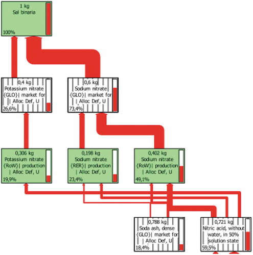
Table 2. Characterisation of 1 kg of each material.
NaNO3 is a compound that, in practically all cases, exceeding 50%, has the greatest contribution to each impact. A comparison of the effects of KNO3, with a higher percentage than the 46% NaNO3 composition, shows that NaNO3 has a generally higher impact in all categories, despite having a lower presence, compared to potassium nitrate. NaNO3 in this formulation has a higher impact on ‘terrestrial ecotoxicity’ and ‘fossil fuel depletion’.
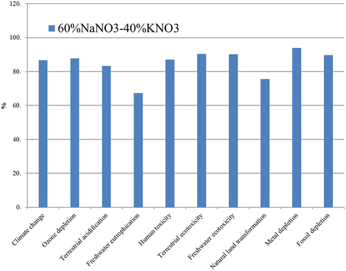
Up to this point the individual characterisation results have been shown, and the assessment is presented in .
Figure 2. Assessment of 1 kg ‘Binary salt’ 60%NaNO3-40%KNO3; Method: ReCiPe Midpoint (H) V1.09/Europe Recipe H/Characterisation.
In any case, these salts will not have a greater impact than Therminol® thermal oil, which, as an HTF medium, exceeds the negative effects of Solar Salt by eight to nine times at these study limits [Citation26].
Studies by Ismael A.S. Ehtiwesh [Citation27] attribute 79% of the environmental impact of a CSP plant to the solar field and among the construction materials, steel has the highest impact, followed by molten salts and thermal oil. In a cradle-to-grave study, C. Mayo et al. [Citation28] studied the LCA of manufacturing and commissioning a CSP steel plant, while Eduard Oró et al. [Citation29], in addition to the manufacturing processes, considered the operational impacts, determining that two-tank molten salt systems with a sensible heat mechanism have a greater environmental impact than molten salt storage systems (TES) with a phase change mechanism (PCM), due to the higher temperature requirement of the former. Therefore, the study limits are decisive to be able to carry out comparative studies between investigations. The standardisation of the results confirms this. The ‘normalization’ makes it possible to relativise how the information of the impact category influences a specific area and between categories, by using global inventories. The normalised results for the functional unit of 1 kg of Solar Salt are shown in .
Figure 3. Standardisation of 1 kg of Solar Salt
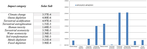
shows how, among the three energy categories (Climate Change, Metal Depletion and Energy Depletion), the difference is not particularly marked. Compared to these, the impact values obtained for other areas such as human health (toxicity), aquatic (eutrophication and ecotoxicity of water) or biometric (soil transformation) are much higher (1.68E-3, 2.56E-3 and 2.58E-3 respectively).
Cost of electricity generation (LCoE) of new fluids
This section includes calculations of the electricity generation costs of the thermal storage systems (TESLCOE) assuming the use of the new fluids designed. Two simulations have been carried out. The first one considers a 50 MW PT technology plant with direct thermal collection and storage. The second one only considered the fluids as a thermal storage medium.
In the following, the individual economic calculations of the TESLCOE are shown, if this fluid circulates through the collector pipes as HTF and is simultaneously a thermal storage medium, as seen in . A 50 MW plant with 6 hours of thermal storage would provide 750 Mwhth of the storage heat for electricity generation, considering an efficiency ratio of 40% [Citation30]. The cost of a system using the current nitrate combination (Na-K) would be more than 25 million euros, based on the unit cost of the reference thermal kWh (kWhth),
Table 3. 750 MWhth TES cost.
Considering the starting information in and the bibliographic data, the electricity generation cost of the storage system has been calculated in , resulting in 0.0313 €/kWhe. It shows the calculation variables used in the mathematical expression of Equationequation (2)(2)
(2) to determine the LCoE of the storage system with this fluid, where TESCAPEX are all capital expenditures necessary for the implementation of the thermal storage system; TESOPEX are the operation and maintenance costs for the system to function properly and r the discount rate to bring the economic data to present value.
Table 4. The LCoE calculation of TES with 60% NaNO3–40% NaNO3 with the indirect collection.
These generation costs correspond to an indirect collection system using thermal oil that restricts the thermal amplitude (ΔT) of the system to 100°C (390°C–290°C). In direct heat collection with the Solar Salt, by adding 50°C of safety above the melting point, the thermal operating range would increase to 223°C (277°C–500°C). shows the mass required for energy storage of 750 MWhth in a direct collection system, increasing the thermal range of the current state of the art, according to the previous paragraph.
Table 5. 60% NaNO3–40% KNO3 mass.
The efficient use of Solar Salt by the absorber tubes would allow having a thermal storage system (TES) with a cost of 0.0243 €/kWhe, as seen in .
Table 6. The LCoE calculation of TES with 60%NaNO3–40% NaNO3 with direct uptake.
Discussion of the LCoE results
In this section, a comparative assessment is made of the economic implications of using the molten salts selected in this work in the TES systems. In this discussion, two assumptions are made, in the case that they are used as the only means of collection and thermal storage (direct collection), or exclusively as a means of storage (indirect collection).
Direct harvesting
According to the calculations carried out in this work, it can be said that the Solar Salt, in economic terms, turned out to have a low cost, as a direct collection thermal storage system. That is, if the fluid passes through the receiver tube, performing the simultaneous function of heat collection and storage, requiring a low volume in a direct TES system (3192 m3). This increase in storage capacity can be associated with an increase in cost as also observed by Sharon J. Wagner [Citation31]. S. Sau et al in a simulation of the use of Solar Salt as a transfer fluid (HTF) and thermal storage in a 50 Mw plant, calculated a mass of approximately 8,400 tons, in line with that obtained in this study (7811 tons), although slightly higher as the storage is 7.5 h. These authors determined an LCoE of 0.22 €/kWhe for the whole system, attributing 0.026 €/kWhe to the storage system, slightly higher than the simulation result obtained in this work (0.024 €/kWhe). The estimated cost reduction of TES, between using thermal oil and Solar Salt, or only Solar Salt, represents a 31% decrease in the LCoE of TES. The approximation of the price reduction obtained in this work is more moderate than that reported by Grogan et al. [Citation32] who estimated a 43% decrease in the electricity generation costs of the storage system (TES). The calculation methodology used in this work does not allow for the economic consideration of the downsizing of TES systems. As less volume of salt is required to produce the same amount of energy, the size of the tanks would also be reduced, which would have a direct impact on lower electricity generation costs.
Indirect capture
If the fluids designed were only to be used as replacement systems for the current thermal storage media, the maximum storage temperature would be limited by the decomposition temperature of the thermal oil, 390°C. The thermal amplitude would be smaller along with the electricity cost ratio, following the mathematical model used in this work. A CSP plant, with the technical characteristics approximated in this study, requires quantities of around or more than 20,000 tonnes of 60% NaNO3–40% KNO3 [Citation33–35]. Research indicates that HTF selection may be location dependent, with thermal oil being able to compete economically with Solar Salt in small systems in areas with low direct normal irradiation (DNI). Christoph A. Pan [Citation36] et al. recently carried out a comparative economic study of the replacement of thermal oil (Therminol®) by Solar Salt, Hitec and Hitec XL. In line with the results obtained in the present work, they concluded that the 60% NaNO3–40% NaNO3 mixture, under all circumstances, provided the greatest cost reduction (LCoE), between 2% and 5%. This decrease is far from those usually referenced in the literature (20%) or the magnitudes obtained in this work for the TES system. The authors point out that in the economic selection criteria of the HTF it is necessary to adjust the size of components, consider the quality of the solar resource and the framework of financial conditions that depend on the geographical location. Observing these economic results and the technical characteristics, the Solar Salt would be the most competitive.
Conclusions
The solar salt mixture and its respective LCA and economic performance were estimated. The novel calculation method employed in this work is in line with the results obtained by other authors and allows us to obtain the economic trends for the use of different fluids with reference to a predefined plant configuration and standardised component sizes. As a future line of research, to obtain more accurate calculations, it would be necessary to consider, in addition to the size variations of the key components, such as the solar field or the thermal storage system, as indicated above, monetising the effects of the fluid on the container materials. Less corrosion would increase the lifetime of the plant, extending the period of electricity generation and revenues.
Acknowledgments
This investigation has been funded by the Ministry of Science and Innovation of Spain under the grant agreement ID: PCI2020-120703-2/AEI/10.13039/501100011033 (EuroPatmos). We acknowledge its support.
Disclosure statement
The authors declare that they have no known competing financial interests or personal relationships that could have appeared to influence the work reported in this paper.
Additional information
Funding
References
- Abbas R, Montes M, Rovira A, et al. Parabolic trough collector or linear Fresnel collector? A comparison of optical features including thermal quality based on commercial solutions. Solar Energy. 2016;124(p):198–215.
- Blanco MJ, Miller S. Introduction to concentrating solar thermal (CST) technologies, in advances in concentrating solar thermal Research and Technology E. Ltd Editor. CSIRO Newcastle, NSW Australia; 2017. p. 3–25.
- Batuecas E, Mayo C, Díaz R, et al. Life cycle assessment of heat transfer fluids in parabolic trough concentrating solar power technology. Sol Energy Mater Sol Cells. 2017;171:91–97.
- Chang ZS, Li X, Xu C, et al. The Design and numerical study of a 2MWh molten salt thermocline tank. Energy Procedia. 2015;69:779–789.
- Yu-Ting W, Shan-Wei L, Ya-Xuan X, et al. Experimental study on the heat transfer characteristics of a low melting point salt in a parabolic trough solar collector system. Appl Therm Eng. 2015;89:748–754.
- Wu Y-T, Li Y, Ren N, et al. Experimental study on the thermal stability of a new molten salt with a low melting point for thermal energy storage applications. Sol Energy Mater Sol Cells. 2018;176:181–189.
- Wu Y-T, Li Y, Lu Y-W, et al. Novel low melting point binary nitrates for thermal energy storage applications. Sol Energy Mater Sol Cells. 2017;164:114–121.
- Wang T, Mantha D, Reddy RG. Novel low melting point quaternary eutectic system for solar thermal energy storage. Appl Energy. 2013;102:1422–1429.
- Ren N, Wu Y-T, Ma C-F, et al. Preparation and thermal properties of quaternary mixed nitrate with low melting point. Sol Energy Mater Sol Cells. 2014;127:6–13.
- Raade JW, Padowitz D. Development of molten salt heat transfer fluid with low melting point and high thermal stability. J. Sol. Energy Eng. 2011; 133(3): 6.
- Pfleger N, Braun M, Eck M, et al. Assessment of novel inorganic storage medium with low melting point. Energy Procedia. 2015;69:988–996.
- Ma Z, Wu Y, Ren N. Heat transfer and storage medium containing low melting point mixed molten salt in European Patent Office. 2015. China.
- Vignarooban K, Xinhai X, Arvay A, et al. Heat transfer fluids for concentrating solar power systems – a review. Appl Energy. 2015;146:383–396.
- Thakare KA. Review on latent heat storage and problems associated with phase change materials. Int J Res Eng Technol. 2015;04(10).
- Mohamed SA, Al-Sulaiman FA, Ibrahim NI. A review on current status and challenges of inorganic phase change materials for thermal energy storage systems. Renew Sust Energ Rev. 2017;70:1072–1089.
- Liu M, Saman W, Bruno F. Review on storage materials and thermal performance enhancement techniques for high temperature phase change thermal storage systems. Renew Sust Energ Rev. 2012;16(4):2118–2132.
- Fernández AG, Galleguillos H, Fuentealba E, et al. Thermal characterization of HITEC molten salt for energy storage in solar linear concentrated technology. J Therm Anal Calorim. 2015;122(1):3–9.
- Kirst W, Nagle W, Castner J. A new heat transfer medium for high temperatures. Trans American Institute Chemical Engineers. 1940;36:371–394.
- Jin Y, An Xuehui CJ. Su Tao, Zhang Peng, Li Zhong. Accurate viscosity measurement of nitrates/nitrites salts for concentrated solar power. Solar Energy, 2016;137:385–392.
- Rogers J, Janz GJ. Melting-crystallization and premelting properties of NaNO3-KNO3 enthalpies and heat capacities. Vol. 27. 1982.
- Ming-Chang L, Chien-Hsun H. Specific heat capacity of molten salt-based alumina nanofluid. Nanoscale Res Lett. 2013;8(292):1–7.
- Bonk A, Sau S, Uranga N, et al. Advanced heat transfer fluids for direct molten salt line-focusing CSP plants. Prog Energy Combust Sci. 2018;67:69–87.
- Serrano-López R, Fradera J, Cuesta-López S. Molten salts database for energy applications. Chem Eng Process Process Intensif. 2013;73:87–102.
- Bashirnezhad K, Bazri SS, Mohammad R, et al. Viscosity of nanofluids: a review of recent experimental studies. Int J Heat Mass Transf. 2016;73(p):114–123.
- Janz GJ, Krebs U, Siegenthaler HF. Molten salts: volume 3, nitrates, nitrites, and mixtures. electrical conductance, density, viscosity, and surface tension data. J Phys Chem Refer Data. 1972; 1(3): 581.
- Batuecas E, Mayo C, Díaz R, et al. Life cycle assessment of heat transfer fluids in parabolic trough concentrating solar power technology. Sol Energy Mater Sol Cells. 2017; 171: 91–97. 09270248.
- Ehtiwesh I, Coelho M, Sousa A. Exergetic and environmental life cycle assessment analysis of concentrated solar power plants. Renew Sust Energ Rev. 2016;56(56):145–155. 13640321
- Mayo C, Batuecas E, Díaz R, et al. Comparative environmental assessment of two materials suited to central tower CSP technology. Solar Energy. 2018;162:178–186. 0038–092X.
- Oró E, Gil A, de Gracia A, et al. Comparative life cycle assessment of thermal energy storage systems for solar power plants. Renewable Energy. 2012; 44: 166–173. 09601481.
- Clifford KH. Concentrating solar power and thermal energy storage.Albuquerque. New Mexico: Sandia National Laboratories. Disponible en. https://www.osti.gov
- Ruiz-Cabañas FJ, Prieto C, Madina V, et al. Materials selection for thermal energy storage systems in parabolic trough collector solar facilities using high chloride content nitrate salts. Sol Energy Mater Sol Cells. 2017;163:134–147. 09270248
- Chen YY, Zhao CY. Thermophysical properties of Ca(NO3)2-NaNO3-KNO3 mixtures for heat transfer and thermal storage. Solar Energy. 2017; 146: 172–179. 0038092X.
- Parrado C, Marzo A, Fuentealba E, et al. LCOE improvement using new molten salts for thermal energy storage in CSP plants. Renew Sust Energ Rev. 2016; 2050(57): 505–514. 1364-0321.
- Liu M, Saman W, Bruno F. Review on storage materials and thermal performance enhancement techniques for high temperature phase change thermal storage systems. Renew Sust Energ Rev. 2012;16(4):2118–2132. 13640321
- Herrmann U, Kelly B, Price H. Two-tank molten salt storage for trough solar power plants. Energy. 2004;29(5–6):883–893. 03605442
- CSP-Plaza. salt melting of the ashalim plot A CSP plant starts. Disponible en: http://en.cspplaza.com/salt-melting-of-the-ashalim-plot-a-csp-plant-starts/Consulta:26-5-2019.