
Abstract
A numerical study is performed to investigate the effects of jet hole shape and channel geometry on impingement cooling for both stationary and rotating condition. Two hole shapes and two channel geometries are introduced to counteract the adverse effects of centrifugal force and Coriolis force which are induced by rotation. Both the fluid and solid part are considered for realizing the conjugate heat transfer simulation. The unsteady k-ω SST turbulence model was employed to obtain the time-averaged Nusselt number distributions, time-averaged temperature and temperature gradient fields and the turbulent flow structure. The results show that the cooling jet from the racetrack-shaped hole can effectively withstand the intensive streamwise crossflow to enhance the heat transfer. The double swirling chamber (DSC) channel significantly improves the heat transfer characteristics on the cambered surface and diminishes the adverse effects of the Coriolis force. The high Nu number region is expanded while the temperature uniformity is improved. The combination of the racetrack-shaped hole and DSC channel provides the highest heat transfer among the four cases. The averaged Nu numbers on both the leading and trailing sides for all tested cases show obvious downtrend as rotation number increases, especially at high Reynolds number.
1. Introduction
To improve the cycle thermal efficiency, modern advanced gas turbine blades are designed to operate at high turbine inlet temperature (TIT). The TIT has already been pushed to 2000 K, which is far more beyond blade material permission and leads to thermal stresses on the blades. Thus, necessary measures must be taken to protect the turbine blades to meet the operation and life span requirements. Particularly, the leading edge of a gas turbine blade is directly heated by the upwind hot gas and suffers a higher heat load. In order to guarantee that the blades operate reliably, improved cooling techniques are applied to enhance heat transfer characters in turbine blades. The application of jet impingement as well as film cooling has been widely utilized in the gas turbine blade. In addition, as the turbine blades are rotating, the Coriolis force deviates the core coolant to the trailing side for a radial outward flow by the rotation and the buoyancy force modifies the flow field by the density variation between the core fluid and near-wall fluid. The extra forces modify the distribution of the crossflow, which has a significant influence on the impingement jet. Therefore, it is of interest to study the heat transfer performance of impingement cooling under the effect of rotation.
A large number of techniques have been tested in recent years to enhance the heat transfer for the turbine internal cooling, such as rib turbulators, dimples, pin fin and jet impingement. Comprehensive reviews of turbine internal cooling have been published by Han et al. [Citation1,Citation2]. According to Ligrani [Citation3], all these techniques enhance the mixing of the flow by increasing the secondary flow and turbulence. Jet impingement, as the most significant potential technique for increasing the local heat transfer coefficient, is widely applied in gas turbines for the cooling of the thermally high-loaded leading edge area.
In the past decades, a number of experimental and numerical studies on the flow and heat transfer characteristics of impingement jets have been carried out. Several detailed reviews by Han et al. [Citation4], Zuckerman et al. [Citation5] and Weigand et al. [Citation6] summarized the important results of research works on jet impingement before 2011. Elebiary et al. [Citation7] tested three flow arrangements at the leading edge and results showed that the spent air of upstream jets significantly diminished the impingement effects on the leading-edge channel walls and reduced the Nusselt number along the axial flow. Xing et al. [Citation8] investigated the effect of crossflow in terms of minimum, intermediate and maximum of the impingement cooling performance. Wang et al. [Citation9,Citation10] studied the effects of vortex generators on the jet impingement heat transfer and found that the presence of vortex generators could reduce the cross-flow momentum to enhance impingement heat transfer. A numerical optimization about impingement cooling was carried out by Yang et al. [Citation11] to research the relationship between heat transfer and pressure drop/mass flow rates. Liu et al. [Citation12] numerically studied the flow and heat transfer of a swirl chamber and found that the thermal performance factor enlarges with increases of Reynolds number, but decreases with increases of jet spacing. Li et al. [Citation13] illustrated the relationship of local Nusselt number and impingement target distance to nozzle diameter. Ligrani et al. [Citation14] studied the combination of impingement and cylinder array target surface and found that the Nusselt number ratios ranged from just above 1 to values as high as 2.25. Uddin et al. [Citation15] found that the excitation of the jet velocity field causes the alteration of near-wall behavior of an impinging jet, which increased the heat transfer in the stagnation zone. Compared with traditional impingement cooling channel in the leading edge of a turbine blade, the double swirling chamber cooling technology (DSC), a novel impingement channel configuration consisting of two partially overlapping, symmetrical chambers, was first introduced by Kusterer et al. [Citation16,Citation17] showed outstanding heat transfer characteristics. Attalla et al. [Citation18] studied the influence of different nozzle shapes on the heat transfer uniformity. The experiments indicated that the circular nozzles provide higher heat transfer than square nozzles and the heat transfer uniformity is mainly effected by the jet-to-jet distance rather than the jet to plate distance. Trinh et al. [Citation19] analyzed the heat transfer influence of three different nozzles on a hemispherical surface. The experimental results showed that the heat transfer rate of a round orifice is higher than other nozzles. Wen et al. [Citation20] studied the nozzle geometry and arrangement effects on impinging jet heat transfer. The experiments found that the jet momentum is determined by the nozzle geometry and the nozzle arrangement diversifies the jet-jet interaction and jet-crossflow interaction.
However, most of the research works above focused on heat transfer and flow structures under stationary circumstances where the Coriolis force and centrifugal force are absent. Under rotating circumstance, Parsons et al. [Citation21] studied the effect of channel rotation on a jet array impingement cooling. That research indicated that as the rotation number increased the Nusselt number ratios for the leading channel target and jet walls decreased down to 15% and for the trailing channel target and jet walls the decrease was down to 20%. The experiments by Hong et al. [Citation22,Citation23] confirmed that the heat/mass transfer was slightly enhanced due to the increased flow mixing by rotation and the crossflow, and H/d affected the averaged Sherwood number value significantly under rotating conditions. Furlani et al. [Citation24] studied the rotating effects on the fluid field in the leading edge cooling channel for gas turbine blades and found that the Coriolis forces induced a strong crossflow deflection towards the duct trailing side. Singh et al. [Citation25] studied the effects of rotation on the heat transfer of jet impingement on a dimpled target surface. It was found that rotation had adverse effects on heat transfer augmentation for all three studied configurations. A numerical investigation by Burberi et al. [Citation26] studied the rotation effects on the internal heat transfer coefficient distribution of a high pressure blade. The study indicated that rotation had minor effects on the flow field in the blade hub region, while the jets appeared to be bent towards the suction side on the tip region.
Although many investigations have been performed on the heat transfer and fluid flow of the impingement cooling on flat or concave targets, most works focused on the effect of jet Reynolds number, jet arrangement and jet-to-jet spacing in stationary circumstances. Many investigations on the rotating condition just pointed out the adverse effects of the rotation on the internal heat transfer. In the present study, in order to study the adverse effects of centrifugal force and Coriolis force in rotating condition, two improved impingement cooling configurations are introduced: the utilization of racetrack-shaped impingement cooling hole could counteract the crossflow as well as the centrifugal force. In addition, the application of a DSC channel may improve the asymmetrical heat transfer distribution caused by the Coriolis force. By considering the conductive heat transfer in the solid blade and to obtain the temperature distribution in the solid domain, the conjugated impingement cooling within the leading edge of a turbine blade in both rotating and stationary conditions is investigated. The suitable leading edge impingement cooling model is established according to the experiment by Cassius et al. [Citation27]. The analysis focuses on the heat transfer and vortex cooling flow characteristics of the jet hole shape and channel geometry in comparison with the baseline case at both stationary and rotating conditions.
2. Numerical approach
2.1. Geometry and configuration
The employed geometric configurations of the leading edge vortex chamber models, which are illustrated in , are derived from the experiments by Cassius et al. [Citation27]. The considered computational domain contains two parts: a fluid part and a solid part in order to realize the conjugate heat transfer simulation in the present work. Cooling air passes through the fluid domain from the entrance of the square supply channel to the exit of the impingement channel via eight impingement holes. The solid domain surrounds the impingement channel to imitate a blade leading edge. The out profile of the solid region is composed of a semi-cylinder surface to represent the leading edge of the blade and two symmetrical tangent extensions to represent a part of the suction and pressure side, respectively.
Figure 1. Geometry details for the impingement cooling system.
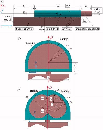
The present study focuses on the impingement channel shape and jet impingement hole shape on the flow structure, heat transfer, friction factor characteristics for a stationary and rotating turbine blade leading edge internal cooling. The cases studied are as follows.
Baseline: Semi-cylinder impingement channel with cylindrical impingement holes ().
Case 1: Semi-cylinder impingement channel with racetrack-shaped impingement holes.
Case 2: DSC impingement channel with cylindrical impingement holes ().
Case 3: DSC impingement channel with racetrack-shaped impingement holes.
The hydraulic diameter (Dh,c) of the cylinder impingement hole is 5 mm, while the width (w) and diameter (d) of the racetrack-shaped impingement hole are 3.7 and 3.14 mm, respectively, which also results in a hydraulic diameter of 5 mm (shown in ). The jet hole pitch (P) is fixed at 25 mm. The geometrical details of the semi-cylinder channel and DSC channel are summarized in . The lengths of the inlet (L1), test (L2) and outlet section (L3) are 100, 220 and 50 mm, respectively. In addition, for rotating cases, the ratio of the mean rotating arm radius-to-jet hydraulic diameter (Rave/Dh,c) is 23.5. The y-axis is the rotation axis and the leading and trailing sides are marked out in .
Figure 2. Sketch of racetrack-shaped hole.
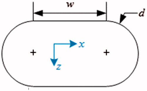
Table 1. Parameter details of the impingement
2.2. Boundary conditions
A uniform heat flux of 2000 W/m2 is applied on the concave outer surface of the solid domain to imitate the outer environment near the leading edge. On the plane outer surface of the solid domain, a constant heat flux of 1500 W/m2 is prescribed in order to consider heat conduction in the solid domain between the supply and impingement channels. The inner surfaces of the solid domain interact with the fluid domain which results in convective heat transfer. Impermeable adiabatic boundary and no-slip smooth wall conditions are implemented over the supply channel walls. A uniform temperature (Tb) of 293.15 K and a turbulence intensity of 5% are applied at the inlet of the fluid domain. The mass flow rate (m) is varied to achieve average jet Reynolds numbers (Res) of 7,854 and 19,635, based on the supply channel hydraulic diameter (Dh,s). An average static pressure () of 1 atm is imposed at the outlet. presents the inlet mass flow rate (m) and the rotating angular velocity (Ω) of the test conditions considered in the present study.
Table 2. Summary of test condition for present study
In this study, the cooling air in the fluid domain is considered as an ideal gas with constant fluid properties (specific heat capacity 1,004.4 J/(kg·K), thermal conductivity W/(m·K), dynamic viscosity 1.831 × 10⁻⁵ Pa·s). The thermal conductivity of the solid material is 20 W/(m·K).
3. Data reduction
The Reynolds number based on the supply channel is defined by EquationEq. (1)(1)
(1) where
is the mean velocity at the inlet of the supply channel.
Similarly, the Reynolds number based on the jet hole is defined by EquationEq. (2)(2)
(2)
The rotation number based on the supply channel is defined by EquationEq. (3)(3)
(3) where Ω is the angular velocity of the rotating channel.
Similarly, the rotation number based on the jet hole is defined by EquationEq. (4)(4)
(4)
The heat transfer coefficient h is defined by EquationEq. (5)(5)
(5)
The Nusselt number is defined by EquationEq. (6)(6)
(6) where λ is the thermal conductivity of air.
The Coriolis force is defined by EquationEq. (7)(7)
(7)
The total pressure loss ratio is defined by EquationEq. (8)(8)
(8)
4. Numerical simulation method
4.1. Selection of turbulence model
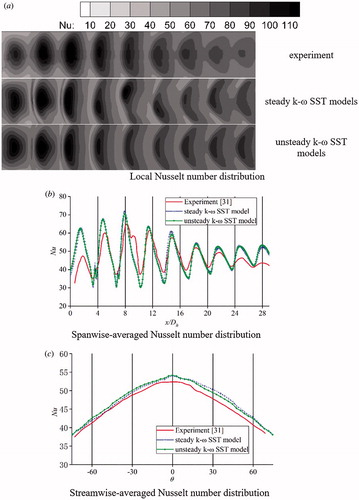
In this study, the k-ω SST model by Menter [Citation28] is employed. The research finding by Kusterer et al. [Citation29] showed that the main flow phenomena are resolved sufficiently well with the k-ω SST model in comparison to experimental data. And the research of Li et al. [Citation30] also illustrated the k-ω SST turbulence model provides the best match to experimental flow and heat transfer results. Yang et al. [Citation31] compared the results of experiment and simulation both with steady and unsteady k-ω SST model. It was found that the numerical results with the unsteady k-ω SST model were in a good agreement with experiment. In order to verify the simulation accuracy, the experiment performed by Yang et al. [Citation31] at Re = 15,000 is selected for comparison in the present study. Numerical computations were conducted with steady and unsteady k-ω SST models by utilizing the commercial solver ANSYS CFX [Citation32]. The comparisons are shown in . The results show that the computed Nusselt number distributions by steady and unsteady k-ω SST models are both in good agreement with experiment. The high heat transfer spots are captured and the local magnitudes match the values of the experiment. In addition, the unsteady k-ω SST models provides a more symmetrical heat transfer distribution which is more close to the experiment. In this way it is concluded that the unsteady k-ω SST models is more accurate to illustrate the skewing effect of the Coriolis force. Thus, the unsteady k-ω SST models is employed in the present research.
Figure 3. Comparison of experiment and simulation.
4.2. Grid independence
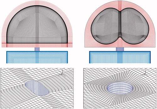
Structured meshes for the simulations were generated by the software ANSYS ICEM. Much attentions are paid on the heat transfer at the interfaces between the solid and fluid domains. Therefore, the nodes on the interfaces between the solid and fluid domains are in one-to-one correspondence to reduce the interpolation error. Meshes with grid adoption of < 1 are applied at all solid boundary walls for all cases. The thickness of the first layer of the near wall grid is 5e–6 m. The qualities of all the mesh element in each case are above 0.45 based on ANSYS ICEM. The accuracy of the numerical results depends on the mesh cell number and the quality. Eight mesh systems with different cell numbers have been considered in the analysis of the independence of grid number. The results shown in illustrate the difference of the time-averaged Nusselt number on the impingement surface as well as the time-averaged total pressure loss. Using the case with mesh number = 8.58 million as the baseline, it is found that the deviation of the time-averaged Nusselt number and total pressure loss in the case with mesh number = 6.43 million are 0.10 and 0.05%, respectively. Thus, the mesh number of 6.43 million is chosen to make a compromise between predicted accuracy and computational efforts. The generated mesh is shown in .
Figure 4. Difference of time-averaged Nusselt number and total pressure loss.
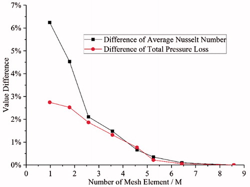
Figure 5. Schematic of a mesh system.
5. Results and discussion
5.1. Temperature and heat transfer
5.1.1. Rotation effect on heat transfer for the baseline case
presents detailed Nusselt number distributions at the interfaces of fluid and solid domains for the semi-cylinder channel at four Rotation number conditions. For illustration purposes, the curved interfaces are transformed to plane surfaces, as shown in . The vertical coordinate (l/Dh,c), here called spanwise, represents the dimensionless arc length and the negative and positive sides represent leading and trailing sides, respectively. The crossflow direction is from left to right.
Figure 6. Nusselt number distributions for semi-cylinder channel at different Rotation numbers.
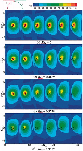
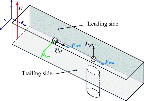
In stationary condition, it should be noted that high heat transfer spots appear at the jet stagnation points. Note that the black circles represent the positions of jet holes. It is obvious that the stagnation points are shifted downstream due to the presence of crossflow. The Nu number shows a symmetrical distribution and the high Nu number spots slightly diminish as the flow moves downstream (x/Dh,c increases). This is because the spent air crossflow bends the impingement jet to the downstream region and reduces the effect of the impingement jet. As the mass flow rate of the crossflow continuously increases, the bend effect is further increased. However, different heat transfer characteristics can be observed in rotating condition. As the Ro number increases, the effects of centrifugal force and Coriolis force are enhanced. The heat transfer reduction and asymmetrical distribution in can be explained by the effects of centrifugal force and Coriolis force, respectively. provides a sketch of velocities and body forces in a rotating impingement cooling system. The leading and trailing sides are defined by the direction of the angular velocity Ω. The directions of the crossflow velocity Ucf and jet velocity Ujet are parallel to the x- and y-axis, respectively. Compared with stationary circumstances, additional centrifugal force is applied on both the impingement jet and crossflow. Thus, the cooling jets are pushed further to the outlet. The decreasing angle between the cooling jet and target surface leads to an obvious heat transfer reduction. In addition, according to EquationEq. (7)(7) , there is no Coriolis force acting on the impingement jet directly. However, the direction of the Coriolis force applied on the crossflow is along the z-axis resulting in that the crossflow carrying the impingement jet deviates to the trailing side. Therefore, the high Nu number spots deviate from the centerline and move to the positive side (trailing side). In , this deviation becomes more noticeable with increasing Ro number and x/Dh,c. Because the semi-cylinder target surface, the effects of the Coriolis force on the angle between the cooling jet and target surface can be ignored. Thus, the Coriolis force mainly affects the heat transfer distribution along the spanwise direction.
Figure 7. Sketch of velocities and body forces in a rotating impingement cooling system.
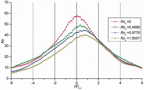
illustrates the average streamwise Nu number distribution of the baseline case at different Ro numbers. It is found that the peak shifts to the positive side (trailing side) and the peak value decreases gradually. Besides that, it is indicated that the rotation mainly influences the heat transfer on the leading side and center part, while the Nu number distribution on the trailing side is insensitive to the Ro number. Both the heat transfer reduction and asymmetrical distribution caused by rotation influence the impingement cooling performance of the blade leading edge.
Figure 8. Average streamwise Nu number distribution of the baseline case.
5.1.2. Rotation effect of racetrack jet hole and DSC on heat transfer and temperature
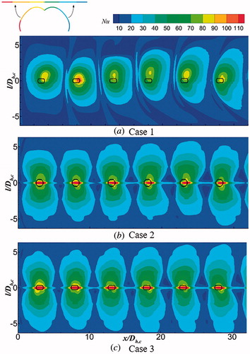
The transformed Nu number distributions at the interfaces of the fluid and solid domains for Cases 1–3 at Res = 7,854 and Ros = 0.9778 are shown in . In the rotating condition, the Nu number distribution of Case 1 is similar to the baseline (), the high heat transfer spot deviates to the trailing and downstream sides. However, the attenuation of heat transfer spots affected by the crossflow is slightly suppressed in Case 1. This indicates that the jet from the racetrack-shaped hole may better penetrate the crossflow. The Nu number in DSC channels shows an almost symmetrical distribution in rotating condition, which illustrates that the Coriolis force effect is diminished by the geometry of the DSC channel. Besides that, compared with the semi-cylinder channel, the high Nu number region expands more along the spanwise direction due to the fillet transition at the margins of the cambered surface. In addition, the combination of the DSC channel and racetrack-shape jet hole slightly enlarges the area of the high heat transfer region.
Figure 9. Nusselt number distributions for three cases at Ros = 0.9778.
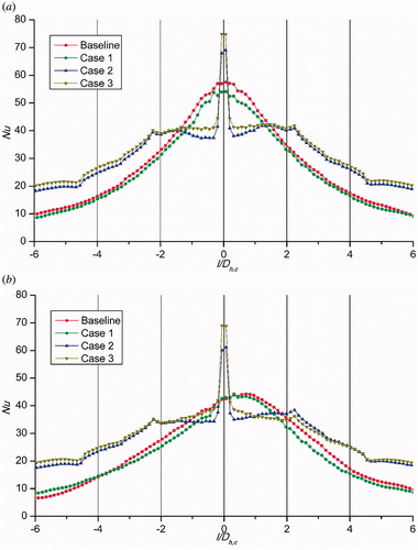
presents the streamwise averaged Nu number distributions for the tested cases at both stationary and rotating conditions. It is noted that the semi-cylinder channel provides higher heat transfer at the central region, especially for the baseline case. However, the Nu number shows a dramatic decline from the center to the margin, which indicates a non-uniform temperature distribution leading to thermal stress augmentation. In contrast, the DSC channel shows a relative uniform heat transfer distribution and the Nu number is enhanced at the margin region because of the fillet. Under rotating condition, for the four cases, the streamwise averaged Nu numbers at the center regions are all lower than for the stationary condition, indicating that rotation contradicts heat transfer improvement. In addition, the heat transfer peaks in the semi-cylinder channels show obvious deviation to the trailing side, while this deviation is not present for DSC channels.
Figure 10. Streamwise averaged Nusselt number distribution at the stationary and rotating conditions.
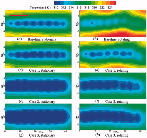
The temperature distributions on the outer surface for the four cases in stationary and rotating (Res = 7854 and Ros = 0.9778) conditions are shown in . The curved surfaces are also transformed to plane surfaces. The negative and positive sides still represent leading and trailing sides, respectively. For all the tested cases, the impingement regions are characterized by low temperature spots. In the stationary cases, the temperature of the baseline case is the highest and the low temperature area expands in the order of Cases 1–3, which indicates that the racetrack-shaped hole and especially the DSC channel both enhance the heat exchange and accordingly reduce the outer side temperature. However, in rotating condition, the area of low temperature spots shrinks in all cases and the shrinking trend aggravates along the streamwise direction due to the augmentation of the crossflow affected by the centrifugal force. In addition, the temperature contours in the baseline case clearly exhibit asymmetrical temperature distribution because the impingement spots deviate to the trailing side, which further deteriorates the heat transfer around the leading margin leading to a hot spot. The overall area-averaged temperature in the rotating condition is 318.9 K as the cooling evaluation reference. A comparison of the contours in indicates that the racetrack-shaped jet hole provides lower temperature similar to the stationary condition and the hot spot is invisible. The area-averaged temperature is reduced by approximately 0.6% to a value of 316.9 K. The large low temperature area in clearly indicates the heat transfer enhancement in the DSC channel. In addition, the nearly symmetrical temperature distributions illustrate that the DSC channel efficiently diminishes the effect of the secondary flow generated by the Coriolis force. The combination of the racetrack-shaped jet hole and DSC channel in Case 3 demonstrates an effective structure to enhance heat transfer. In Case 3, the temperature is overall at the lowest level as the area-averaged temperature is reduced by approximately 1.9% to 312.9 K. The temperature in Case 2 is in between the two aforementioned cases. The area-averaged temperature is reduced by about 1.6% to 313.7 K.
Figure 11. Temperature distributions on the outer solid surface.
5.2. Fluid field and temperature uniformity
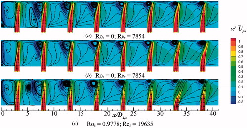
In order to illustrate the effects of the streamwise crossflow on the impingement cooling, the v/ contours on the x-y center plane in the baseline case for three Ros and Res conditions are shown in . In the stationary case at Res = 7,854 (), the streamwise crossflow slightly bends the impingement jets to the downstream and this behavior becomes more obvious for the downstream jets as the streamwise crossflow is enhanced gradually. Besides that, the constant shrinkage of vortices upstream the impingement spots also indicates that the angle between the impingement jet and target surface diminishes. Hence, the intensity of the impingement spots is decreased along the streamwise direction. In the stationary channel at Res = 19,635, both the momentum of the impingement jet and streamwise crossflow are enhanced proportionally. Thus, the flow field shows a similar distribution as that at Res = 7,854. However, compared with the stationary cases, the velocity v in the rotating channel at Ros = 0.9778 is significantly lower, especially for the jet close to the outlet, which is mainly caused by the shifting of jets to the trailing side in different degrees due to the Coriolis force effects. In addition, the crooked jet in also indicates that the crossflow as well as the centrifugal force bends the jets to the downstream in the rotating condition.
Figure 12. v/Ujet distribution on the symmetry plane for the baseline case.
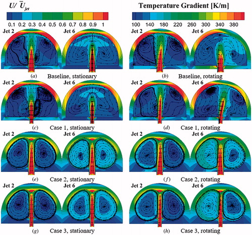
presents the U/ distributions at the constant axial position x/Dh,c = 8 (second jet hole) and x/Dh,c = 28 (sixth jet hole) for the four tested cases in both stationary and rotating conditions. In addition, the temperature gradient contours inside the solid domain are shown. For the stationary condition, in the baseline channel, distinct vortices induced by the semi-cylinder shape of the channel and jets can be observed. The high velocity area close to the channel roof corresponds to the heat transfer augmentation region. As the velocity decreases along the arc wall, high temperature gradient regions appear at both flanks, which indicates an undesirable temperature distribution in terms of temperature uniformity. Case 1 exhibits a similar velocity and temperature gradient distributions as the baseline case. The vortices which have the same direction merge together as the air flows downstream. However, the DSC channels in Cases 2 and 3 illustrate distinct velocity and temperature gradient distributions. In Case 2, a pair of vortices occupies the whole channel indicating a more sufficient heat and mass exchange. The cooling air from the jet maintains a higher velocity until it hits the target surface, which indicates that more momentum are available for impingement cooling rather than being consumed as the air crosses the channel. It also shows that the velocity near the channel wall is higher than that in the semi-cylinder channel leading to more intensive heat convection. In Case 3, the cooling air through the racetrack-shaped jet hole keeps even higher velocity than Case 2, which may be due to the jet from a longer hole (length along the streamwise) counteracts the bend effect of the streamwise crossflow better. Besides that, the temperature gradient contours in Cases 2 and 3 indicate that the DSC channel provides a more uniform temperature distribution except at the area near the impingement spots. In terms of thermal stresses, the DSC channel is a suitable configuration. In addition, the flow fields as well as temperature gradient distributions of the four cases are highly symmetrical in stationary conditions. However, due to the effects of the Coriolis force, flow fields and temperature gradients are redistributed in the rotating condition. In , the jets lean to the trailing side resulting in an asymmetrical flow field distribution. This behavior is more obvious at the downstream position as the flow develops in the channel. In addition, the temperature gradient distribution shows that the leaning jet mitigates the temperature gradient on the trailing flank. Case 1 provides a similar flow field distribution with the baseline case except that the high velocity area of the jets is attenuated slower from the second to the sixth jet. However, the jet deviation is effectively suppressed in the DSC channel as shown in . Thus, the adverse effects of the Coriolis force are controlled resulting in a relatively symmetrical flow field and temperature gradient distributions in the rotating condition. It is found that the temperature gradient in the DSC channels are hardly affected by the rotation. The average temperature gradient in the rotating case is 297.76 K/m as the reference. The average temperature gradients in Cases 1–3 at the rotating condition are 296.94, 213.96 and 209.39 K/m, respectively. The average temperature gradients are reduced approximately 0.28, 28.14 and 29.68%, respectively.
Figure 13. U/Ujet and temperature gradient distributions at two axial positions.
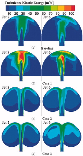
The turbulence kinetic energy (TKE) distributions at the sections x/Dh,c = 8 (second jet hole) and x/Dh,c = 28 (sixth jet hole) for the four cases in the rotating condition are shown in . In the baseline case, a high TKE appears at the region near the arc solid wall and the mixing region around the cooling jet. The high TKE region near the solid wall indicates an intensive turbulent flow and accelerated mass exchange resulting in heat transfer augmentation. The high TKE at the mixing region represents the strong interaction between jet and crossflow leading to an intensive heat and mass exchange. In case 1, a much higher TKE region in the channel can be observed, which indicates that the racetrack-shaped hole effectively promotes turbulent flow and heat exchange. In the DSC channel cases, the area of high TKE close to the solid wall is expanded. Thus, the heat transfer on the two flanks is improved. The racetrack-shaped hole in the DSC channel also provides positive effects to enhance the TKE.
Figure 14. Turbulence kinetic energy distributions at Ros = 0.9778.
5.3. Overall performance
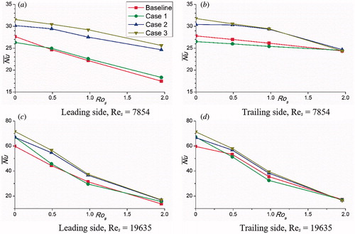
illustrates the average Nu number on the leading and trailing sides for the four tested cases at different Ros and Res. At low Reynolds number condition, it can be noted that Case 3 provides the highest heat transfer in , followed by Case 2. The average Nu numbers for Baseline, Cases 1–3 at the stationary condition are 27.74, 26.42, 30.30, and 31.67, respectively. The Nu number on the leading and trailing sides shows the downtrend as the Ros number is increasing, especially at the leading side. At Ros = 0.9778, the average Nu numbers on the leading side for Baseline, Cases 11–3 are 22.18, 22.60, 27.54 and 29.22. Compared with the values at stationary condition, the Nu numbers decrease approximately 19.85, 14.17, 8.74 and 7.38%, respectively. Meanwhile, the Nu numbers on the trailing side decrease approximately 5.96, 4.09, 3.48 and 7.33% to the values of 26.16, 25.43, 29.37 and 29.46, respectively. In addition, at Ros = 1.9557, the Nu numbers for the four cases on the trailing side are comparable, which indicates that the effects of channel geometry or jet hole shape on the trailing side heat transfer are negligible. At high Reynolds number condition (), more significant drops for all tested cases can be observed as the Ros number is increasing. It should be noted that at high Ros number circumstances (Ros = 1.9557), higher Re number condition provides lower heat transfer, which is opposite to stationary circumstances. The heat transfer abilities of these cases at Res = 19,635 still follow the same order as those at Res = 7,854.
Figure 15. Averaged Nusselt number for four cases at Res = 7,854 and 19,635; Ros = 0 – 1. 9557.
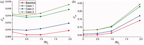
provides the total pressure loss ratio (Cpt) of the tested cases. Generally, the total pressure loss is enlarged as the Ros number is increased. The figures indicate that the racetrack-shaped jet hole (Cases 1 and 3) more obviously improves the total pressure loss than the DSC channel. At the low Reynolds number condition, as Ros number increases from 0 to 1.9557, the total pressure losses for Baseline, Cases 1–3 increase approximately 4.26, 12.06, 17.82 and 18.62%, respectively. However, the increases are 180.31, 183.33, 195.70 and 199.26%, respectively, at high Reynolds number condition.
Figure 16. Total pressure drop ratio for four cases at Res = 7,854 and 19,635; Ros = 0 – 1. 9557.
6. Conclusion
In this study, the heat transfer characteristics and fluid flow in stationary and rotating impingement cooling channel with two jet hole shapes and two channel geometries were numerically studied for a range of Ros numbers from 0–1.9557 and Res number of 7,854 and 19,635. The main conclusion from the present investigation are summarized as follows.
Due to the Coriolis force and centrifugal force, the stagnation points are shifted downstream further while deviating to the trailing side, resulting in more crooked cooling jets and impingement reduction. The cooling jet from the racetrack-shaped hole can withstand the streamwise crossflow better to enhance the heat transfer slightly. The utilization of the DSC channel significantly improves the heat transfer characteristics on the cambered surface. Due to the geometry of the DSC channel, a pair of vortices can be generated automatically by the cooling jets. The vortices show a good performance to diminish the adverse effects of Coriolis force and to expand the high Nu number region. The combination of a racetrack-shaped hole and DSC channel provides the highest heat transfer among the four considered cases. At Ros = 0.9778 and Res = 7,854, compared with the baseline case, the overall area-averaged temperatures on the outer solid surface of Cases 1–3 decrease approximately 0.6, 1.6 and 1.9% to the values of 316.9, 313.7 and 312.9 K, respectively. Furthermore, the DSC channel shows much better temperature uniformity than the semi-cylinder channel. In addition, the average Nu numbers on both leading and trailing sides show a more obvious decrease at high Reynolds number condition. The total pressure loss is less sensitive to the DSC channel than the racetrack-shaped jet hole.
| Nomenclature | ||
| English symbols | = | |
| Cpt | = | total pressure loss ratio |
| Dh,c | = | jet hole hydraulic diameter (m) |
| Dh,s | = | supply channel hydraulic diameter (m) |
| Fcor | = | Coriolis force vector (N) |
| Fcen | = | centrifugal force vector (N) |
| h | = | heat transfer coefficient (W m−2 K−1) |
| l | = | arc length (m) |
| m | = | mass flow rate (kg s−1) |
| = | average Nusselt number | |
| Nu | = | Nusselt number |
| = | average static pressure (N m−2) | |
| = | average total pressure (N m−2) | |
| P | = | jet hole pitch (m) |
| q | = | heat flux (W m−2) |
| Rave | = | mean rotating radius (m) |
| Re | = | Reynolds number |
| Ro | = | rotation number |
| T | = | temperature (K) |
| Ty | = | air bulk temperature (K) |
| Tw | = | wall temperature (K) |
| Ucf | = | crossflow velocity vector (m s−1) |
| Ujet | = | jet velocity vector (m s−1) |
| = | mean velocity (m s−1) | |
| v | = | velocity along y-axis (m s−1) |
| Greek symbols | = | |
| λ | = | thermal conductivity of air (W m−1 K−1) |
| μ | = | air dynamic viscosity (kg m−1 s−1) |
| ρ | = | air bulk density (kg m−3) |
| Ω | = | angular velocity of rotational channel (rad s−1) |
| Subscripts | = | |
| in | = | inlet of the supply channel |
| jet | = | based on jet hole |
| out | = | outlet of the impingement channel |
| s | = | based on supply channel |
| Abbreviations | = | |
| DSC | = | double swirling chamber |
| TIT | = | turbine inlet temperature |
| TKE | = | turbulence kinetic energy |
Additional information
Funding
References
- J.-C. Han and M. Huh, “Recent studies in turbine blade internal cooling,” Heat. Transf. Res., vol. 41, no. 8, pp. 803–828, 2010. DOI: 10.1615/HeatTransRes.v41.i8.30.
- J.-C. Han, S. Dutta, and S. Ekkad, Gas Turbine Heat Transfer and Cooling Technology, 2nd ed. New York, NY, USA: CRC Press, chap. 4, 2012.
- P. Ligrani, “Heat transfer augmentation technologies for internal cooling of turbine components of gas turbine engines,” IJRM., vol. 2013, pp. 275653, 2013.
- B. Han and R. Goldstein, “Jet‐impingement heat transfer in gas turbine systems,” Ann. N Y. Acad. Sci., vol. 934, no. 1, pp. 147–161, 2006.
- N. Zuckerman and N. Lior, “Jet impingement heat transfer: physics, correlations, and numerical modeling,” in Advances in Heat Transfer, J. P. H. A. B.-C. George, A. Greene, and I. C. Young, Eds. Amsterdam, Netherlands: Elsevier, 2006, pp. 565–631.
- B. Weigand and S. Spring, “Multiple jet impingement - a review,” Heat. Transf. Res., vol. 42, no. 2, pp. 101–142, 2011. DOI: 10.1615/HeatTransRes.v42.i2.30.
- K. Elebiary and M. Taslim, “Experimental/numerical crossover jet impingement in an airfoil leading-edge cooling channel,” J. Turbomach., vol. 135, no. 1, pp. 011037, 2012. DOI: 10.1115/1.4006420.
- Y. Xing, S. Spring, and B. Weigand, “Experimental and numerical investigation of heat transfer characteristics of inline and staggered arrays of impinging jets,” J. Heat. Trans.-T. ASME., vol. 132, no. 9, pp. 092201, 2010.
- C. Wang, L. Wang, and B. Sundén, “A novel control of jet impingement heat transfer in cross-flow by a vortex generator pair,” Int. J. Heat. Mass. Transfer., vol. 88, pp. 82–90, 2015. DOI: 10.1016/j.ijheatmasstransfer.2015.04.056.
- C. Wang, L. Luo, L. Wang, and B. Sundén, “Effects of vortex generators on the jet impingement heat transfer at different cross-flow reynolds numbers,” Int. J. Heat. Mass. Transfer., vol. 96, pp. 278–286, 2016. DOI: 10.1016/j.ijheatmasstransfer.2016.01.642.
- L. Yang, Z. Min, P. N. Sarwesh, and M. K. Chyu, “Numerical optimizations of hybrid-linked jet impingement heat transfer based on the genetic algorithm,” Numer. Heat. Tr. A. Appl., vol. 70, no. 11, pp. 1179–1194, 2016. DOI: 10.1080/10407782.2016.1243946.
- Z. Liu, J. Li, Z. Feng, and T. Simon, “Numerical study on the effect of jet spacing on the swirl flow and heat transfer in the turbine airfoil leading edge region,” Numer. Heat. Tr. A. Appl., vol. 70, no. 9, pp. 980–994, 2016. DOI: 10.1080/10407782.2016.1230381.
- D. Singh, B. Premachandran, and S. Kohli, “Numerical simulation of the jet impingement cooling of a circular cylinder,” Numer. Heat. Tr. A. Appl., vol. 64, no. 2, pp. 153–185, 2013. DOI: 10.1080/10407782.2013.772869.
- P. M. Ligrani, Z. Ren, and W. C. Buzzard, “Impingement jet array heat transfer with small-scale cylinder target surface roughness arrays,” Int. J. Heat. Mass. Transfer., vol. 107, pp. 895–905, 2017. DOI: 10.1016/j.ijheatmasstransfer.2016.10.123.
- N. Uddin, S. O. Neumann, and B. Weigand, “Heat transfer enhancement by velocity field excitation for an impinging round jet,” Numer. Heat. Tr. A. Appl., vol. 69, no. 8, pp. 811–824, 2016.
- K. Kusterer et al., “Novel gas turbine blade leading edge cooling configuration using advanced double swirl chambers,” presented at the ASME Turbo Expo 2015: Turbine Technical Conference and Exposition, American Society of Mechanical Engineers, Montreal, Canada, pp. V05AT11A006, 2015.
- K. Kusterer et al., “Conjugate heat transfer analysis of a blade leading edge cooling configuration using double swirl chambers, presented at the ASME Turbo Expo 2016: Turbomachinery Technical Conference and Exposition, American Society of Mechanical Engineers, Seoul, Korea, pp. V05BT11A010, 2016. DOI: 10.1016/j.expthermflusci.2015.08.006.
- M. Attalla, H. M. Maghrabie, A. Qayyum, A. G. Al-Hasnawi, and E. Specht, “Influence of the nozzle shape on heat transfer uniformity for in-line array of impinging air jets,” Appl. Therm. Eng., vol. 120, pp. 160–169, 2017.
- X. T. Trinh, M. Fénot, and E. Dorignac, “The effect of nozzle geometry on local convective heat transfer to unconfined impinging air jets,” Exp. Therm. Fluid. Sci., vol. 70, pp. 1–16, 2016.
- Z.-X. Wen, Y.-L. He, X.-W. Cao, and C. Yan, “Numerical study of impinging jets heat transfer with different nozzle geometries and arrangements for a ground fast cooling simulation device,” Int. J. Heat. Mass. Transfer., vol. 95, pp. 321–335, 2016. DOI: 10.1016/j.ijheatmasstransfer.2015.12.022.
- J. A. Parsons and J.-C. Han, “Rotation effect on jet impingement heat transfer in smooth rectangular channels with heated target walls and radially outward cross flow,” Int. J. Heat. Mass. Transfer., vol. 41, no. 13, pp. 2059–2071, 1998. DOI: 10.1016/S0017-9310(97)00286-X.
- S. K. Hong, D. H. Lee, and H. H. Cho, “Effect of rotation on heat/mass transfer for an impingement/effusion cooling system,” J. Heat. Trans.-T. ASME., vol. 132, no. 11, pp. 112210–114501, 2010.
- S. K. Hong, D. H. Lee, and H. H. Cho, “Heat/mass transfer measurement on concave surface in rotating jet impingement,” J. Mech. Sci. Technol., vol. 22, no. 10, pp. 1952–1958, 2008.
- L. Furlani, A. Armellini, and L. Casarsa, “Rotational effects on the flow field inside a leading edge impingement cooling passage,” Exp. Therm. Fluid. Sci., vol. 76, pp. 57–66, 2016. DOI: 10.1016/j.expthermflusci.2016.03.004.
- P. Singh and S. Ekkad, “Effects of rotation on heat transfer due to jet impingement on cylindrical dimpled target surface,” presented at the ASME Turbo Expo 2016: Turbomachinery Technical Conference and Exposition, American Society of Mechanical Engineers, Seoul, Korea, pp. V05BT16A010, 2016.
- E. Burberi et al., “Effect of rotation on a gas turbine blade internal cooling system: numerical investigation,” J. Turbomach., vol. 139, no. 3, pp. 031005, 2016.
- C. A. Elston and L. M. Wright, “Leading edge jet impingement under high rotation numbers,” J. Therm. Sci. Eng. Appl., vol. 9, no. 2, pp. 021010, 2017.
- F. R. Menter, “Two-equation eddy-viscosity turbulence models for engineering applications,” AIAA. J., vol. 32, no. 8, pp. 1598–1605, 1994.
- K. Kusterer et al., “Heat transfer enhancement for gas turbine internal cooling by application of double swirl cooling chambers,” presented at the in: ASME Turbo Expo 2013: Turbine Technical Conference and Exposition, American Society of Mechanical Engineers, San Antonio, TX, USA, pp. V03AT12A027-V003AT012A027, 2013.
- W. Li, J. Ren, J. Hongde, Y. Luan, and P. Ligrani, “Assessment of six turbulence models for modeling and predicting narrow passage flows, part 1: Impingement jets,” Numer. Heat. Tr. A. Appl., vol. 69, no. 5, pp. 109–127, 2016. DOI: 10.1080/10407782.2015.1069665.
- L. Yang, J. Ren, H. Jiang, and P. Ligrani, “Experimental and numerical investigation of unsteady impingement cooling within a blade leading edge passage,” Int. J. Heat. Mass. Transfer., vol. 71, pp. 57–68, 2014. DOI: 10.1016/j.ijheatmasstransfer.2013.12.006.
- ANSYS CFX, Reference Guide, Release, 17.0, 2016.