
Abstract
In this article, numerical simulations have been conducted on the heat transfer effect of dimple/protrusion layouts of a pin-finned wedge duct. Conjugate heat transfer calculations are further performed to investigate the cooling effect of modified schemes with dimples and protrusions added. Comparisons are carried out with a turbine second stage guide vane employed as the prototype. The dimple/protrusion-pin fin arrangement is set as the optimum one obtained above, and dimple depth/protrusion height varies from 0.2 to 0.3 times the structure diameter. It is found that the side-by-side arrangement and protrusion structure is more beneficial for the wedge duct endwall heat transfer. Comparison with the prototype blade shows that the addition of both dimples and protrusions are helpful in enhancing the trailing edge cooling effect. The cooling effect is increased with an increase in dimple depth/protrusion height. The results also show that the modified blade with protrusions attached at 0.3 height saves 0.48 g/s cooling mass flow and reaches the most positive performance with a 17 K, 14 K average temperature reduction, 0.022, 0.018 cooling effect increasing for pressure, suction side, respectively.
1. Introduction
The most advanced gas turbine has attained a temperature over 2200 K which is far beyond the maximum metal allowance temperature, less than 1300 K, currently. The trailing edge is exposed to a high severe thermal load which should be designed with a small cross-sectional area and narrow internal passage to satisfy the aerodynamic demands. Therefore, it is significant to find efficient and reliable methods of the effective cooling of the blade trailing edge for the safety and stability of gas turbines.
The typical structure of gas turbine trailing edge cooling is mainly pin fins which can ensure structural integrity of the trailing edge slot, arrays of ribs or pin fins are arranged in the coolant passage to connect the pressure side and the suction side walls. Additionally, they can also act as turbulators promoting the internal convective heat transfer in the coolant passage and controlling the blade’s coolant mass flux [Citation1]. The physical composition of pin fins heat transfer is not unique because it depends upon a number of parameters. Metzger et al. [Citation2] and [Citation3] experimentally studied the flow and heat transfer characteristics of a rectangular channel with short pin-fins at Reynolds number varying from 10,000 to 50,000, pin streamwise spacing ratio 1.32 to 2.5, and imposed empirical correlations between average array Nusselt number, pin fins spacing and Reynolds number. For the case where the trailing edge is convergent (wedge-shaped), most studies focused on the influence of the outlet of cold air [Citation4], Reynolds number [Citation4], the layout of pin-fins [Citation4–6], and the shape of pin-fins [Citation7–9] on heat transfer and flow resistance.
In a real blade, the converged trailing edge channel is always accompanied with large flow resistance due to the gradually reduced gap area from inlet to outlet which brings a relatively large flow resistance. The addition of various pin-fins arrangement plays a positive role in the heat transfer enhancement. However, the attendance of a variety of pin-fins may further increase the flow resistance, about 5–70 friction factor increase compared with a smooth channel [Citation10] and [Citation11]. The cooling structure design should have the merits of a high heat transfer coefficient and low flow resistance. Dimples/protrusions are striking due to the ability of giving local heat transfer enhancement with small flow resistance. For the dimpled channel surface, the heat transfer can achieve 1.8–3.8 enhancement while the flow resistance can reach about 0.25–4.5 times of that in smooth channel [Citation10–13]. For a protrusion channel, 3.5–14 and 12–18 increase for heat transfer and flow resistance, respectively, have been found [Citation10],[Citation14], and [Citation15].
Recently, researchers introduced dimples/protrusions into the cooling structures of trailing edge investigations. Lan et al. [Citation16] compared the effects of heat transfer and flow resistance characteristics between rib-dimple and rib-protrusion structures in a rectangular channel by numerical simulations. Murata et al. [Citation17] combined dimples, pin-fins and crosswise rib-turbulators together to enhance the heat transfer in a rectangular channel. Luo et al. [Citation18] numerically compared the effect of dimple positions on the flow structure, heat transfer, and friction factor in a staggered pin-fin wedge duct with varying Reynolds number. Among the tested cases, the in-line case achieves the best heat transfer enhancement with low friction factor penalty. Investigations about the influence of dimple locations on the flow structure and heat transfer characteristics in a 90°-turned channel with varying pin fins layout have been conducted [Citation19]. It was found that the dimple locations had effect on the heat transfer augmentation but a very small effect on the friction factor. Rao [Citation20] tested the dimple depth effect on the pressure loss and heat transfer characteristics in a pin fin-dimple channel, where dimples were located between the pin fins and revealed the underlying mechanisms by associating the velocity, and temperature distributions with the pressure loss, and heat transfer together at Reynolds number changing from 8,200 to 50,500. Luo [Citation21] further simulated the dimple depth and converging angle contributions to the heat transfer and friction factor on a dimpled pin-fin wedge duct and concluded that the dimple case with 0.2 relative depth showed the best heat transfer performance at 12.7° converging angle. However, a deeper dimple with larger converging angle provided a better thermal performance.
In this article, numerical simulations are carried out to investigate the heat transfer effect of dimples/protrusions in a wedge duct with pin fins. Three different dimple/protrusions positions are employed with constant pin fins layout and Reynolds number. Conjugated heat transfer calculations of a real vane are employed to evaluate the cooling effect of trailing-edge modification cases with dimples/protrusions added to an existing turbine second stage guide vane. The relative dimples depth/protrusions height is varying from 0.2 to 0.3.
2. General description of physical models
2.1. Wedge duct
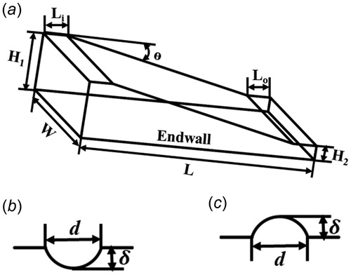
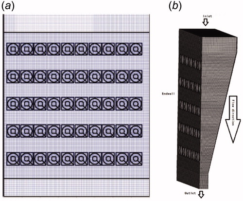
The geometrical model of the wedge duct with pin fins and dimples/protrusions arrangement are identical to that in Luo et al. [Citation18], as shown in . The wedge duct has an inlet length Li=20 mm and outlet length Lo=20 mm. The duct's length, L is 200 mm and its width, W is 160 mm. The inlet height H1 is 48 mm, the outlet height H2 is 12 mm, and the converging angle of the wedge duct is 12.7°. The dimple/protrusion parameters are shown in , in which the dimple/protrusion diameter, d is 12 mm. The dimple depth/protrusion height, δ is 2.4mm (δ/d = 0.2).
Figure 1. Wedge duct and dimple configurations. (a) Wedge configurations, (b) dimple configurations, (c) protrusion configurations.
The pin fins are arranged in a staggered layout in the wedge duct with distances Sx=30 mm and Sy=30 mm, while the pin fin diameter, d is 12 mm (). show the various pin fin-dimples/protrusions arrangements in the wedge duct.
Figure 2. Pin fin arrangement and those with dimples/protrusions positions. (a) pin fin arrangement, (b) case 1, 4, (c) case 2, 5, (d) case 3, 6. Pin fins-the white circles, dimples/protrusions-filled circles.
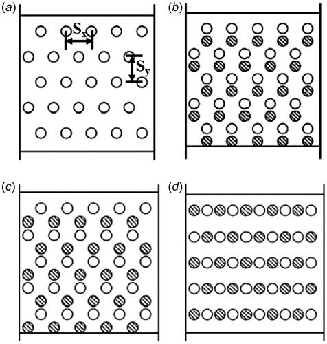
Six cases with different dimples/protrusions positions are considered:
Case 1, 4: The dimples/protrusions are located directly downstream of the pin fins, where the distance between pin fin and dimple/protrusions centers is 15 mm.
Case 2, 5: The dimples/protrusions are located directly upstream of the pin fins. The distance between the pin fin and dimple/protrusions centers is 15 mm.
Case 3, 6: The dimples/protrusions are positioned side-by-side with the pin fins. The distance between the dimple/protrusions and pin fin centers is 15 mm.
2.2. Blade
The prototype is a certain turbine second stage guide vane. The blade is bended and twisted, and the inner part of the blade is a shock sleeve arranged with 12 rows of impingement holes. The trailing edge is cooled by half split, and five rows of pin fins are employed. The blade model added with dimples is presented in . The positions of dimples/protrusions are settled between the adjacent pin fins. The height of the dimple/protrusion is set as 0.2d, 0.3d. Detailed information for the cases is presented in .
Figure 3. The schematic of the blade with dimples added between the pin fins at trailing edge.
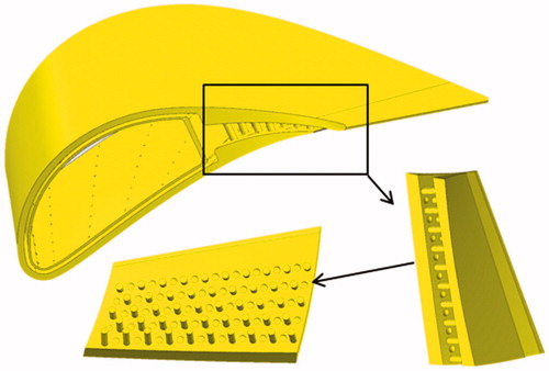
Table 1. Details of the different cases.
3. Computational details
3.1. Overview
In this study, analysis of three-dimensional turbulent flow and heat transfer in a pin finned wedge duct with dimples/protrusions and flow-heat transfer coupled calculations for the blade was carried out by the kω-SST-Gamma-Theta model within the framework of the commercial software CFX [Citation22]. The kω-SST-Gamma-Theta model was chosen as it is claimed to offer the best tradeoff between accuracy and computational effort for the parameters considered [Citation23]. The finite volume method was used to solve the governing equations of fluid flow and heat transfer with appropriate boundary conditions. An in-house code based on MATLAB was used to create the computational models and generate the structured grids for the pin finned wedge duct with dimples/protrusions. The ICEM software was employed to generate the blade mesh.
To improve the computational accuracy, second order high-resolution advection scheme and high-resolution turbulence numerics were employed to discretize the governing equations. All predicted quantities were at steady state. The minimum convergence criterion for the continuity equation, velocity and turbulence quantities is 1e − 4 and 1e − 6 for the energy equation.
3.2. Solution method
The steady incompressible viscous fluid flow motion is governed by the equations [Citation24]:
Continuity equation
(1)
Momentum equation
(2)
Energy equation for fluid
(3)
where
is density and
is the velocity vector,
is the dynamic viscosity, and P is the pressure.
is the specific heat,
is the thermal conductivity, and T is the temperature.
The kω-SST-γ-θ turbulence model can be expressed by the following equations.
The turbulent kinetic energy (TKE) k equation:
(4)
The equation of the dissipation rate reads
(5)
where
(6)
(7)
(8)
(9)
(10)
(11a)
(11b)
(12)
(13)
(14)
(15)
(16)
(17)
(18)
(19)
The constants have the values: = 0.85,
= 1
= 0.65,
= 0.856,
= 0.075,
= 0.0828,
= 0.09,
,
.
The γ-θ model is derived from two transport equations which are used to describe the full transition model (i.e. intermittency equation for γ and transition onset criterion in terms of the momentum thickness Reynolds number for θ). This model is recommended for general-purpose applications as a transition model by using a new empirical correlation. This new correlation has been developed to cover standard bypass transition as well as flows in low-free stream turbulence environments. More details concerning the γ-θ model can be found in [Citation25].
3.3. Boundary conditions
In this study, the fluid in this study is dry, compressible air with varying thermal physical properties. The flow process is three-dimensional, turbulent, steady, and non-rotating. The high-resolution advection scheme and high-resolution turbulence numeric are applied to discretize the governing equations of continuity, momentum, energy, TKE, and turbulent dissipation rate.
For the wedge duct, the endwall surfaces, pin fin surfaces, and left and right wall surfaces of the wedge duct are considered to be the heat transfer areas. According to the experimental setup, a constant and uniform temperature (303.15 K) was applied on these wall surfaces. The inlet temperature was 333.15 K. A turbulence intensity of 5% was chosen as the inlet condition. The Reynolds number is set as 36750.
Concerning the flow-heat transfer coupled calculations, a STEEL material is selected for the blade. The main stream turbulence is 5%. Given the main inlet total temperature and total pressure distribution along the leaf height, the given back pressure is distributed along the leaf height. The two sides of the gas flow channel are periodic rotating boundaries. The coolant inlet is a given total temperature of 635 K, and the total pressure is 797960.15 Pa.
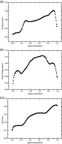
The calculated boundary conditions are derived from the results of the whole level calculation and are processed with dimensions, as shown in .
Figure 4. Boundary details of the conjugate heat transfer calculation.
Dimensionless temperature is set as:
(20)
Dimensionless pressure is set as:
(21)
where
,
are the averaged total temperature and pressure of the main inlet, respectively.
,
are the local temperature and pressure, respectively.
3.4. Modeling and mesh generation
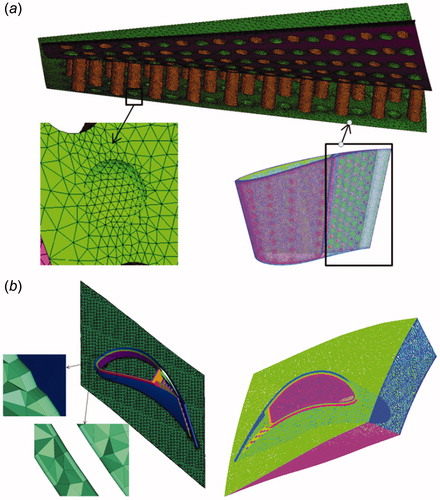
Structured grids with boundary layers are generated by an in-house code developed in MATLAB. According to the test of grid independence, the total number of grid elements is set to 4.5 million and the value of near endwall y + is less than 1. The thickness of the first layer of the near wall grid is 1e − 6 m. The generated grids are displayed in , where both 2- and 3-dimensional grids are plotted in , respectively.
Figure 5. Grids for wedge duct with pin fins and dimples (case 2). (a) 2D grids, (b) 3D grids.
The ICEM software is used to create the grid of the blade. Due to the complex structure, the fluid domain and solid domain all use the unstructured drawing grid (), and the mesh of the fluid solid interface grid is encrypted to ensure Y + max <2.4.
Figure 6. The fluid and solid domain grid for cooling blade.
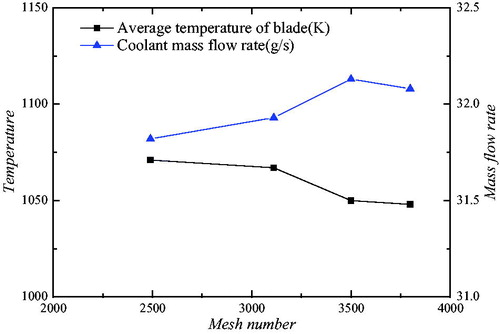
As shown in , when the total number of mesh elements is about 38 − 39.4 million, the error of blade surface temperature and air inlet flow rate is less than 1%, so the grid parameters of all schemes in this paper are set to 37.98 million grid elements.
Figure 7. Mesh validation for blade calculation.
3.5. Computational fluid dynamics (CFD) validations
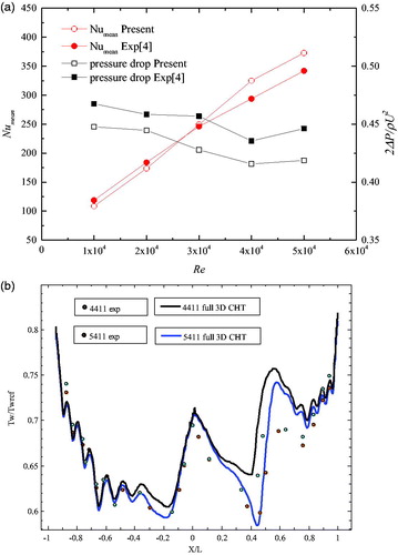
Before the dimples are applied, it is necessary to compare the simulated endwall heat transfer and pressure drop for a wedge duct without dimples against available experimental data [Citation4]. shows the Numean and pressure drop profiles over the Reynolds number range 10,000 − 50,000. The maximum deviation between the experimental and CFD results is 8.54% at Re =50,000. The pressure drop comparison between the CFD and experimental results is presented in . It is obvious that the numerical results of the pressure drop in the wedge duct with pin fins are reasonably well in agreement with the experimental data. The comparison of the wall temperature at the mid span between the 3-dimensional conjugate heat transfer and experimental results [Citation26] (two operating conditions, i.e. 4,411 and 5,411) is shown in . It is found that the CFD shows good agreement with the experimental results. In what follows, for the sake of convenient comparison of various dimple/protrusion-pin fin wedge ducts, the wedge duct without dimples is referred to as the baseline case. The Reynolds number is fixed at 30,000 for this study.
Figure 8. CFD validation.
4. Data reduction
The Reynolds number is defined as
(22)
The heat transfer coefficient is
(23)
The Nusselt number
(24)
The distribution of the cooling effect of the blade surface is defined as follows
(25)
The is the wall temperature of the blade, and the
is the total temperature of the inlet of the air.
The integrated cooling effect of the blade is defined as follows:
(26)
where
is the average wall temperature for blade.
In the equations above, is the heat flux.
,
,
are the fluid density, dynamic viscosity, and thermal conductivity, respectively.
represents the temperature difference between the inlet and endwall surface.
5. Results and discussions
5.1. Heat transfer and fluid flow for wedge duct
5.1.1. One-dimensional results
shows the averaged Nusselt number, Numean, on the endwall surface of different cases. For the pin-finned wedge duct with dimples (cases 1 − 3), Numean achieves the largest value at side-by-side, and smallest value for downstream placement. A 13.35% increase is reached for the side-by-side arrangement compared with that of the downstream one. The increase is 13.11% for the upstream case. This can be also obtained for the pin-finned wedge duct with protrusions (cases 4 − 6), and the increase is 17.34%, 11.40% for side-by-side, downstream arrangement compared with the downstream (case 4). It is obvious that Numean with protrusions is larger than for the dimples at the same dimples/protrusions arrangement. Especially for the side-by-side placement, a 5.78% increase is obtained for case 6 compared with case 3. It can be inferred that the side-by-side arrangement and protrusion structure is more beneficial for the endwall average heat transfer. The following discussions about local parameters are provided to give some explanations of the phenomena obtained above.
Table 2. Averaged Nusselt number for different cases.
5.1.2. Local heat transfer and flow dynamics
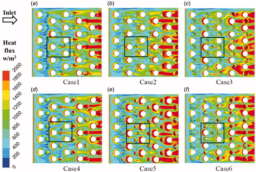
illustrates the heat flux contours on the endwall for the dimples and protrusions with different layouts. A continuous and significant increase of the heat flux value occurs along the streamwise direction which can be related to the flow acceleration effect of the converging duct [Citation21]. The heat flux distributions around the pin fins are obviously higher for the side-by-side arrangement than for the upstream one, and higher for the upstream compared with the downstream arrangement for both dimples and protrusions. A higher value is also observed for protrusions cases compared with the dimples cases at the same arrangement. There trends are the same as for the Numean. For further detailed analysis and convenient comparison, a region at the same position for cases 1 − 7 (named region A) containing a whole pin fin and a whole dimple/protrusion is chosen as identified by the black box ().
Figure 9. Comparison of endwall heat flux distributions: (a) Case1, (b) Case2, (c) Case3, (d) Case4, (e) Case5, (f) Case6. Region A (black box).
present the endwall streamlines, TKE and heat flux distributions for cases 1–6 in region A. The dimple/protrusion on the centerline is concerned in the discussion below except for cases 2 and 4.
Figure 10. Comparison of streamlines in relevant regions. (a) Case1, (b) Case2, (c) Case3, (d) Case4, (e) Case5, (f) Case6.
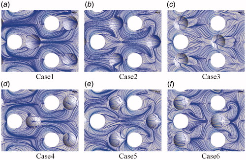
Figure 11. Comparison of TKE distribution in relevant regions. (a) Case1, (b) Case2, (c) Case3, (d) Case4, (e) Case5, (f) Case6.
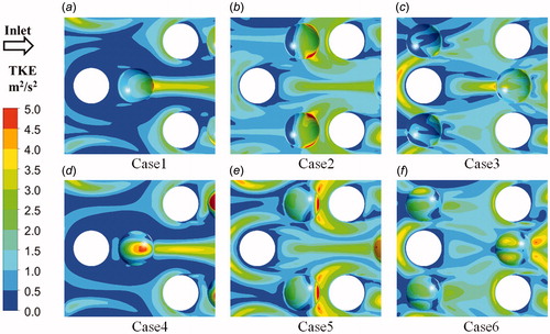
Figure 12. Comparison of heat flux distribution in relevant regions. (a) Case1, (b) Case2, (c) Case3, (d) Case4, (e) Case5, (f) Case6.
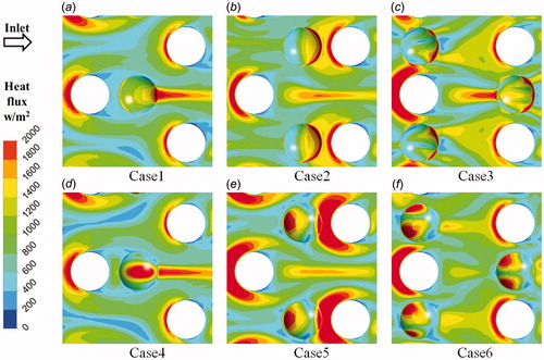
For case 1 and case 4, the dimples and protrusions are located downstream of the pin fins’ wake region. Reattachment flow can be observed on the back part of the dimple () accompanied with a low TKE value () and this can be the reason for the high heat flux back of the dimple (). Impingement occurs at the up and down parts of the protrusion () which induces a high TKE on the center part of the protrusion () and thus a high heat flux is obtained (). With the dimples/protrusions moving to the upstream position (case 2 in Figures10–12b, case 5 in ), separation occurs at the back part of the dimple (). Thus a high TKE region is attained at this part () which is followed by a relative high heat flux (). Reattachment and separation can be observed at front and rear part of the protrusion (), respectively. The TKE reaches a relative high magnitude in those regions as mentioned above (), and thus high heat flux regions occur (). Concerning case 3 and case 6, the dimples/protrusions are situated side-by-side with pin fins. The flow on the dimple shows a typical reattachment, and separation characteristics (). Impingement and separation flow can also be observed in the protrusion case (). The TKE distribution at front of the pin fins is higher in case 6 () compared with that in case 3 (). The relative high heat flux situation can also be observed on the protrusions () compared to the dimples ().
Overall speaking, downstream arrangement shows a poorer heat flux distribution performance, and side-by-side arrangement performs better. The protrusion cases are better than the dimples at same arrangement. Those characteristics are consistent with the one-dimensional data discussed in Section 5.1.1 which can be linked to the higher disturbances mentioned above.
5.2. Heat transfer and fluid flow for blade
5.2.1. One-dimensional results
compares the one-dimensional parameters between prototype (baseline) and modified blade cases (cases 7–10). Generally speaking, the presence of dimples and protrusions in side-by-side arrangement can improve the heat transfer performance with less cooling air of the blade trailing edge for both suction and pressure sides. As the dimple depth increases from 0.2 to 0.3, the average temperature and cooling mass flow decrease, and the cooling effect increases for both pressure and suction sides. This can also be observed in the protrusion cases with increasing protrusion height. At a constant dimple depth/protrusion height, the presence of protrusions provides more effective performance in cooling the trailing edge with less cooling air. It is obvious that, case 10., that is, protrusions at 0.3 height scheme has 0.48 g/s cooling mass flow savings and reaches the most positive performance with 17 K, and 14 K average temperature reduction, 0.022, and 0.018 cooling effect increasing for pressure, and suction side, respectively. The parameters of the pressure side contours are further illustrated.
Table 3. Comparison of one-dimensional parameters.
5.2.2. Heat transfer characteristics for inner surface of the trailing edge
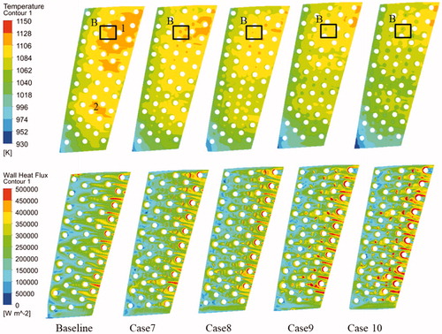
compares the wall heat flux and temperature contours on the pressure side inner face of the blade trailing edge for the prototype baseline and modified schemes (case 7–10). For the baseline, a high temperature region (orange colored) occurs on the rear part of the trailing edge shroud at half (marked 1) and middle part of the hub half (marked 2). The high temperature region 1 decreases with an increase of the dimple depth from 0.2 (case 7) to 0.3 (case 8), and region 2 disappears as the dimple is employed. This can also be observed for the protrusion cases and as the protrusion height increases (cases 9, 10) compared with the baseline case. The reduction in temperature distributions can be directly related to the high heat flux. It is no doubt that the presence of dimples (cases 7, 8) and protrusions (cases 9, 10) plays an effective role in enhancing the heat transfer and cooling of the inner surface of the blade trailing edge. The wall heat flux shows a significant high magnitude on the dimple rear part of the 2, 3, and 4 column pin fins which is accompanied by a reduction of the high temperature region (orange and yellow colored) compared with the baseline case. Concerning case 9 and 10, the increase in wall heat flux and decrease in temperature distributions can also be found with the presence of protrusions compared to the baseline. For convenience of a detailed analysis, a region containing a whole dimple/protrusion is chosen as marked by the black box (named as region B).
Figure 13. Temperature (up) and wall heat flux (down) distributions on the pressure side inner face of blade trailing edge for different cases.
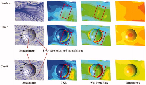
The differences between baseline case 7 and 8 in streamlines, TKE, wall heat flux, and temperature of region B are presented in . As shown by the streamlines, a typical dimple fluid flow is obtained, that is, flow reattachment at the middle of the dimple, flow separation, and reattachment downstream of the dimple. Obviously, a relative high and high TKE region occur at the upstream and downstream edge portions of the dimple, respectively, where a flow acceleration happens as the fluid flows over the edge before separation. With this high flow disturbance mentioned above, the boundary layer may be thinner which can induce a higher wall heat flux at the edge portion. A relative high TKE region can be observed coinciding with the position of the reattachment and can be related to the reattaching flow process. Concerning the temperature distributions, a remarkable decrease is present at region B due to the flow disturbance induced by the dimple compared with the baseline. With increasing dimple depth (from 0.2 in case 7 to 0.3 in case 8), the wall heat flux in the edge region and the downstream reattachment region increases, and the temperature distributions decrease which can be attributed to the stronger disturbance flow caused by a deeper dimple.
Figure 14. Streamlines, TKE, Wall heat flux and temperature distributions on the dimple of trailing edge pressure side.
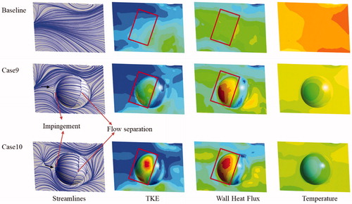
For the protrusion cases, the streamlines, TKE, wall heat flux, and temperature of region B are also compared with the baseline (shown in ). The incoming flow impinges on to the front face of the protrusion, and thus induces an increase of TKE. High disturbance flow enhances the heat transfer and a remarkable high wall heat flux can be observed which is accompanied by a temperature decrease in this region compared with the baseline. This heat transfer enhancement is more obvious as the protrusion is higher.
Figure 15. Streamlines, TKE, Wall heat flux and temperature distributions on the protrusion of trailing edge pressure side.
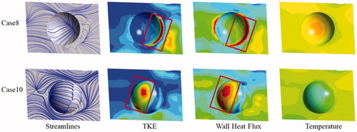
compares the heat transfer ability between dimple and protrusion cases at the same dimple depth and protrusion height (0.3). As analyzed above, flow acceleration at the edge portion and reattachment effect downstream the dimple can be responsible for the increase in wall heat transfer enhancement. Impingement on the front face of the protrusion is related to the remarkable improvement in wall heat flux. Comparing the temperature distributions, a distinct decrease appears as the structure changes from dimple to protrusion. It can be concluded that the presence of the protrusion has a higher potential to improve the wall heat transfer and decrease the wall temperature compared with the dimple case at same dimple depth and protrusion height.
Figure 16. Streamlines, TKE, Wall heat flux and temperature comparisons between dimple and protrusion for δ/d = 0.3 of trailing edge pressure side.
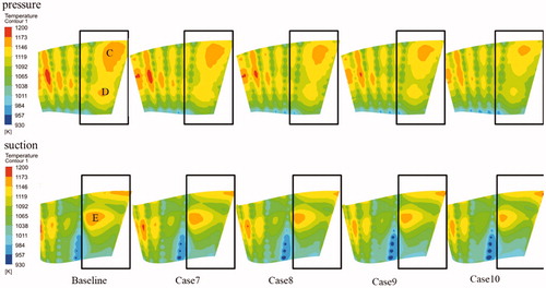
The above contours and streamlines are located at the pressure side of the cooling passage of the blade trailing edge. Temperature distributions on the inner face can directly impact the blade surface by solid conduction for this blade without film holes. presents the temperature distributions on both pressure and suction sides of the blade surface. For the baseline contours, a large high temperature zone (region C) is located at the upper part of the blade pressure side. A smaller one can be observed at the lower part (region D). Concerning the blade suction side, a relative high temperature region occurs at the upper part near the middle of the blade trailing edge (region E). The C region is narrowed as dimple and protrusion are added, and decreases with increasing dimple depth/protrusion height. Region D disappears for the modified cases (cases 7 − 10). Concerning region E, the same can be also observed. Generally speaking, the temperature reduction effect is more remarkable for the cases where the dimple depth and protrusion height is larger, and the protrusion cases show higher potential in blade trailing edge temperature decrease compared with the dimple case at the same dimple depth and protrusion height. Those characteristics are consistent with the one-dimensional data discussed in Section 5.1.1 which can be linked to the higher disturbance mentioned above. Those characteristics agree with the one-dimensional data presented in Section 5.2.1.
Figure 17. Temperature distributions on the blade surface pressure (upper) and suction (lower) side.
6. Conclusions
In this article, numerical simulations have been conducted on the heat transfer effect of dimples/protrusions location in a wedge duct with pin fins. Conjugate heat transfer calculations are further performed to compare the heat transfer influence of different dimple depth/protrusion height on a real blade trailing edge with the optimum arrangement obtained above. The kω-SST-Gamma-Theta turbulence model is applied in this investigation. The main conclusions are summarized below:
Between upstream, downstream, and side-by-side layouts, side-by-side arrangement achieves the highest heat transfer performance, while the upstream one reaches the lowest. The improvement of the side-by-side for the upstream cases is 13.35% and 17.34%, respectively, for the dimple and protrusion wedge duct.
At the same dimples/protrusions layout, cases with protrusion are more beneficial for the endwall average heat transfer. Compared with the dimpled wedge duct, the increases of the protrusions is 0.64%, 2.18%, and 5.78% for upstream, downstream and side-by-side arrangement, respectively.
Comparison with the prototype blade, it shows that the presence of dimples/protrusions has an cooling effect of the blade trailing edge with less cooling mass flow. By increasing the dimple depth/protrusion height, reduction is obtained both in the blade average temperature and cooling mass flow.
The protrusions at 0.3 height scheme saves 0.48 g/s cooling mass flow and reaches the most positive performance with 17K and 14K average temperature reduction, 0.022 and 0.018 cooling effect increase for the pressure, suction sides, respectively.
| Nomenclature | ||
| d | = | diameter of dimple, protrusion and pin fin, mm |
| = | heat transfer coefficient, W/(m2.K) | |
| H1 | = | inlet height of wedge duct, mm |
| H2 | = | outlet height of wedge duct, mm |
| Li | = | inlet length of wedge duct, mm |
| Lo | = | outlet length of wedge duct, mm |
| L | = | length of wedge duct, mm |
| Numean | = | surface averaged Nusselt number, Pa |
| = | averaged total pressure of the main inlet, Pa | |
| = | dimensionless pressure, Pa | |
| = | heat flux, W/m2 | |
| Sx | = | streamwise distance between the pin fins, mm |
| Sy | = | spanwise distance between the pin fins, mm |
| = | average wall temperature for blade, K | |
| = | cooling air temperature, K | |
| = | averaged total temperature of the main inlet, K | |
| = | blade temperature, K | |
| = | dimensionless temperature, K | |
| TKE | = | turbulent kinetic energy, m2/s2 |
| = | wedge duct velocity inlet, m/s | |
| W | = | width of wedge duct, mm |
| = | pressure difference between the duct inlet and outlet | |
| = | temperature difference between the inlet and endwall surface, K | |
| = | dimple depth/protrusion height, mm | |
| = | converging angle of wedge duct, | |
| = | thermal conductivity of air, W/(m.K) | |
| = | dynamic viscosity, Pa.s | |
| = | density of air, kg/m3 | |
Additional information
Funding
References
- P. Martini, A. Schulz, and H. J. Bauer, “Film cooling effectiveness and heat transfer on the trailing edge cutback of gas turbine airfoils with various internal cooling designs, ASME,” J. Turbomach., vol. 128, no. 1, pp. 196–205, 2006.
- D. E. Metzger, R. A. Berry, and J. P. Bronson, “Developing heat transfer in rectangular ducts with staggered arrays of short pin fins,” J. Heat Transfer, vol. 104, no. 4, pp. 700–706, 1982.
- D. E. Metzger, and S. W. Haley, “Heat transfer experiments and flow visualization for arrays of short pin fins,” ASME, New York, Paper No. 82-GT-138, 1982.
- J. J. Hwang, and C. C. Lui, “Measurement of endwall heat transfer and pressure drop in a Pin-Fin wedge duct,” Int. J. Heat Mass Transfer, vol. 45, no. 4, pp. 877–889, 2002.
- C. Bianchini, B. Facchini, F. Simonetti, L. Tarchi, and S. Zecchi, “Numerical and experimental investigation of turning flow effects on innovative pin fin arrangements for trailing edge cooling configurations, ASME,” J. Turbomach., vol. 134, no. 2, pp. 021005, 2012.
- G. Liao, X. Wang, X. Bai, D. Zhu, and J. Yao, “Numerical investigation on the Flow and Heat Transfer Characteristics of the Superheated Steam in the Wedge Duct with Pin-Fins,” ASME, New York, Paper No. GT2013-94205, 2000.
- J. J. Hwang, and C. C. Lu, “Lateral-flow effect on endwall heat transfer and pressure drop in a pin-fin trapezoidal duct of various pin shapes,” ASME, New York, Paper No. GT2000-0232, 2000.
- S. C. Siw, M. K. Chyu, and M. A. Alvin, “Heat transfer enhancement of internal cooling passage with triangular and semi-circular shaped pin-fin arrays,” ASME, New York, Paper No. GT2012-69266, 2012.
- J. Kruekels, S. Naik, A. Lerch, and A. Sedlov, “Heat transfer in a vane trailing edge passage with conical pins and pin-turbulator integrated configurations,” ASME, New York, Paper No. GT2014-25522, 2014.
- P. Ligrani, M. M. Oliveira, and T. Blaskovich, “Comparison of heat transfer augmentation techniques,” AIAA J., vol. 41, no. 3, pp. 337–362, 2003.
- P. Ligrani, “Heat transfer augmentation technologies for internal cooling of turbine components of gas turbine engine,” Int. J. Rotat. Mach., vol. 2013, pp. 1–32, 2013.
- C. N. Jordan, and L. M. Wright, “Heat transfer enhancement in a rectangular (AR =3:1) channel with V-shaped dimples,” ASME, New York, Paper No. GT2011-46128, 2011.
- J. Turnow, N. Kornev, V. Zhdanov, and E. Hassel, “Flow structures and heat transfer on dimples in a staggered arrangement,” Int. J. Heat Fluid Flow., vol. 35, pp. 168–175, 2012.
- S. D. Hwang, H. G. Kwon, and H. H. Cho, “Heat transfer with dimple/protrusion arrays in a rectangular duct with a low Reynolds number range,” Int. J. Heat Fluid Flow., vol. 29, no. 4, pp. 916–926, 2008.
- L. Luo, W. Du, F. Wen, S. Wang, and Z. Zhao, “Convergence angles effect on the,” Heat Trans. Res., vol. 48, no. 14, pp. 1237–1262, 2017.
- J. Lan, Y. Xie, and D. Zhang, “Heat transfer enhancement in a rectangular channel with the combination of ribs dimples and protrusions,” ASME, New York, Paper No. GT2011-46031, 2011.
- A. Murata, S. Nishida, H. Saito, K. Iwamoto, Y. Okita, and C. Nakamata, “Heat transfer enhancement due to combination of dimples, protrusions, and ribs in narrow internal passage of gas turbine blade,” ASME, New York, Paper No. GT2011-45356, 2011.
- L. Luo, C. Wang, L. Wang, B. Sundén, and S. Wang, “Heat transfer and friction factor performance in a pin fin wedge duct with different dimple arrangements,” Numer. Heat Transfer A Appl., vol. 69, no. 2, pp. 209–226, 2016.
- L. Luo, W. Du, S. Wang, B. Sunden, and X. Zhang, “Flow structure and heat transfer characteristics of a 90°-turned Pin-Finned wedge duct with dimples at different locations,” Numer. Heat Transfer A Appl., vol. 73, no. 3, pp. 143–162, 2018.
- Y. Rao, C. Wan, and Y. Xu, “An experimental study of pressure loss and heat transfer in the pin Fin-Dimple channels with various dimple depths,” Int. J. Heat Mass Transfer, vol. 55, no. 23–24, pp. 6723–6733, 2012.
- L. Luo, C. Wang, L. Wang, B. Sundén, and S. Wang, “Heat transfer and friction factor in a Dimple-Pin fin wedge duct with various dimple depth and converging angle,” Int. J. Num. Meth. Heat Fluid Flow., vol. 26, no. 6, pp. 1954–1974, 2016.
- ANSYS CFX, Reference Guide, Release, vol. 13, 2010.
- P. Dong, “Research on conjugate heat transfer simulation of aero turbine engine air-cooled vane,” Ph.D. thesis, Harbin Institute of Technology, Harbin, China, 2009.
- H. K. Versteeg, and W. Malalasekera, An Introduction to Computational Fluid Dynamics: The Finite Volume Method, 2nd ed., Essex, UK: Longman, 2007.
- F. R. Menter, “Two-Equation Eddy-Viscosity turbulence models for engineering applications,” AIAA J, vol. 32, no. 8, pp. 1598–1605, 1994.
- L. D. Hylton, M. S. Milhec, E. R. Turner, D. A. Nealy, and R. E. York, “Analytical and experimental evaluation of the heat transfer distribution over the surface of turbine vanes,” NASA-CR, vol. 168015, 1983.