
 ?Mathematical formulae have been encoded as MathML and are displayed in this HTML version using MathJax in order to improve their display. Uncheck the box to turn MathJax off. This feature requires Javascript. Click on a formula to zoom.
Abstract
Effects of droplet characteristics of mist/air cooling on heat transfer for three pin-fin structures are investigated. The round-tip pin-fin structure is newly proposed with partial detachment from one endwall with a round-shaped tip structure. A flat-tip pin-fin with partial detachment and a traditional pin-fin with full attachment serve as references. Reynolds-averaged Navier-Stokes equations and the shear-stress-transport turbulence model are applied. Influences of initial mist temperature, initial mist diameter and initial mist velocity are analyzed in the Reynolds number range 15,000 to 50,000. The round-tip pin-finned channel has highest heat transfer coefficient and lowest pressure loss among the structures. Heat transfer enhancement increases first gradually and then decreases sharply with increasing initial mist diameter but an optimal diameter exists for the highest Nusselt numbers. Nusselt number decreases monotonically with increasing initial mist temperature. Droplet movement and heat transfer are nearly independent of initial mist velocity.
1. Introduction
To achieve higher thermal efficiency and output power, gas turbines as the indispensable power equipment are designed towards higher inlet temperature. Restricted by the limitation of the material melting temperature, the study regarding cooling technologies has become an important research area. Advanced cooling technologies containing external cooling and internal cooling are widely employed to protect the hot sections from thermal failure nowadays. Different from external cooling, internal cooling can be free from some harsh situations, such as the potential clogging of the slot holes or the added aerodynamic losses brought by the coolant jets, which film cooling might go through. However, it is always accompanied with pressure loss besides enhancing heat transfer for internal cooling. Therefore, designing some innovative and effective internal cooling schemes is of great demand.
In the internal passages, vortex generators are frequently applied to enhance the convective heat transfer performance by increasing the flow turbulence intensity, and the pin-fin structure is an important one. Pin-fin arrays consist of multiple rows of short cylindrical columns and are always used in the trailing edge region of the gas turbine blades due to the thin and narrow space. The application of pin-fins can not only induce vortices to obtain higher convective heat transfer coefficients, but also increase the heat transfer area and strengthen the mechanical structure by connecting the pressure side and the suction side. To date, there exists a vast literature with respect to pin-fin array configurations and innovative pin-fin geometrical structures. The first investigation on pin-fin array configurations in the trailing edge region was carried out by Metzger et al. [Citation1], and they demonstrated that the heat transfer performance in staggered arrangements is much better than that in inline arrangements. Then, many studies have been carried out on the effects of the factors like the pin-fin pitch and array configuration on the heat transfer characteristics [Citation2–5]. Besides, the section shape is another key factor which has an obvious impact on the thermal performance. Some simple shaped pin-fins [Citation6–7] like cubic, square, diamond, and triangle pin-fins and other innovative shaped pin-fins [Citation8–10] like fan-shaped, circular stepped and conical pin-fins have been studied to investigate the effects on flow structure and heat transfer. The results revealed that pin-fins with sharp edges can induce additional vortices and lead to higher flow turbulence intensity which will make contributions to the heat transfer enhancement, but will always be accompanied with more pressure loss. Moreover, when applying pin-fins to the main body of the blade, the design innovations of pin-fins are more flexible because there is no need to take the structural strength into account. Hence, many researchers performed numerical and experimental studies to look into the detailed heat transfer and pressure drop characteristics of the pin-fins with detachment [Citation11–13], and found that pin-fins with detachment showed higher heat transfer rates compared with the corresponding cases with full attachment.
Note that, in the studies mentioned above, most of them seek to enhance heat transfer by modifying the geometries by using air as the main coolant. However, in recent decades, many researchers started to turn to some alternative coolants, and especially for the coolants like steam, mist/air and mist/steam, which might have better performance in cooling of the high thermal loaded components if compared to the traditional coolant, that is, air. In 1990s, Corman [Citation14] proposed the concept of the closed-steam cooling in gas turbines. Different from air, there is no need to extract the coolant from the compressor which will have a detrimental effect on the overall efficiency due to the reduction of the working fluid and the additional leakage losses. Besides, compared to air, steam has obvious advantages because of the higher heat capacity. Then, many studies regarding the effect of steam cooling for the internal structures have been carried out as follows. Shui et al. [Citation15] and Liu et al. [Citation16, Citation17] performed research on the heat transfer and flow characteristics in a rib-roughed channel with steam cooling numerically and experimentally, and the results suggested that in comparison with air-only cooling, the heat transfer coefficient could be increased to be 1.19–1.32 times higher with steam cooling. Wang et al. [Citation18] numerically studied the mist/steam heat transfer of multiple rows of impinging jets, and the results indicated that the wall temperature can be significantly reduced with the injection of mists. Besides, Guo et al. [Citation19] discussed the effect of aspect ratio on the flow and heat transfer characteristics of mist/steam cooling in rectangular ribbed channels.
Although steam cooling or mist/steam cooling displays obviously better heat transfer enhancement, the drawback is that the cooling system might need to be redesigned because it should be a closed loop and the consumption of steam also brings the penalty of the overall efficiency of the system. Therefore, mist/air cooling has more attractive advantages, and over the past decades, more and more attention has been paid on it. In Wang’s group [Citation20–23], a series of studies on the heat transfer performance of mist/air cooling were conducted numerically and experimentally. In their simulations [Citation20, Citation21], the mist/air cooling characteristics on a flat plate and rotating blades were studied and the results showed that the application of the mists can remarkably reduce the wall temperature and improve the heat transfer enhancement. In their experiments [Citation22, Citation23], the adiabatic film cooling effectiveness on a plate was evaluated, and it could be obviously increased at low blowing ratios. In addition, Zhou et al. [Citation24] performed a computational analysis of mist/air film cooling on a flat plate with different hole types, and Wang et al. [Citation25] carried out a study on the film cooling effectiveness with and without mist injection on a flat plate with deposition. Zhang et al. [Citation26] investigated the effect of the droplet characteristics and rotation speed on flow structure and heat transfer of mist/air cooling in a rotating ribbed channel numerically, and the results indicated that the initial mist temperature, diameter and rotation speed have a significant impact on the thermal performance, while the effect of the initial mist velocity can be negligible.
The review of literature above showed that quite few studies paid attention on the effects of the droplet characteristics of mist/air cooling on flow structure and heat transfer in a pin-finned internal channel. Besides, in the authors’ previous study, a newly proposed pin-fin structure, the round-tip pin-fin with partial detachment presents good thermal performance which could effectively enhance the heat transfer performance and decrease the pressure loss. Consequently, in this study a CFD simulation on flow mechanism and heat transfer in three different pin-finned channels with the round-tip pin-fin, flat-tip pin-fin and traditional pin-fin structures are performed, and the effects of the initial mist diameter, temperature and velocity on the mist/air cooling performance are investigated in detail.
2. Physical model and numerical methods
2.1. Computational model
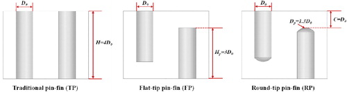
The present study is focused on the heat transfer performance of a rectangular internal cooling channel with pin-fins in a staggered arrangement, and the geometry of the computational model is based on an experimental study by Siw et al. [Citation12]. The schematics of the computational configuration are given in . In the channel, 18 rows of pin-fins are arranged in the streamwise direction, while in the spanwise direction, the periodic conditions are applied to save computational efforts. The transversal and longitudinal spacing between two adjacent pin-fins are 2.5D0, where D0 is the pin-fin diameter. For the sake of numerical simulations, the entrance and exit regions are extended to gain a fully developed and uniform flow at the inlet and avoid the backflow at the outlet. In the investigation, three different pin-fin structures are considered and compared, the round-tip pin-fin (RT), the flat-tip pin-fin (FT) and the traditional pin-fin (RT), and the details can be seen in . The round-tip pin-fin is a newly proposed pin-fin with partial detachment from one endwall by the authors [Citation27]. It consists of a cylindrical body and a round structure on the tip. Different from the round-tip pin-fin, the flat-tip pin-fin is just a cylindrical body unshrouded with a tip clearance to one endwall, and the traditional pin-fin is the one which attaches the two endwalls.
Figure 1. Schematic diagram of computational model.
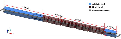
Figure 2. Geometrical structure of different pin-fins.
2.2. Boundary conditions
summarizes the boundary conditions for all calculations in this article. The ideal air is used as the main coolant in the internal channel. A uniform velocity, Va, based on Reynolds numbers within the studied range from 15,000 to 50,000, the total temperature of the coolant, T0, and the main flow turbulence intensity of 5% are given at the channel inlet. The static pressure, pout, is applied at the outlet which is set as the atmospheric pressure. In the heated region, all walls are assigned with a constant temperature, Tw, while in the unheated region, adiabatic and no-slip boundary conditions are specified on the walls. In order to save computational resources, periodic boundary conditions are imposed on the two spanwise sidewalls. For mist cooling, the coolant is mixed with a small amount of water droplets and a gas mixture of water vapor and air. Before injection, the mass flow ratio of water droplets to the main flow is 1%. In this investigation, the droplet characteristics of mist/air cooling have been studied, including the initial mist diameter, dm, initial mist temperature, Tm, initial mist velocity, Vm, and the values are presented in . It is worth to mention that the mist injection points are equally spaced at the inlet. In the study, the Lagrangian method is utilized to predict mists. Because the mass flow ratio of water droplets is quite small, mists are regarded as a discrete phase, and the condition “rebound” is adopted which means the water droplets will rebound off the wall when reaching the endwall.
Table 1. Boundary conditions.
In the study, all the calculations are performed for steady state and the commercial software ANSYS CFX 16.0 is used. In order to guarantee convergence of the steady state, the root mean square normalized residuals should be always below 10−5 for each variable, and the heat transfer coefficient monitored on the channel endwall should not change anymore.
2.3. Mesh sensitive study
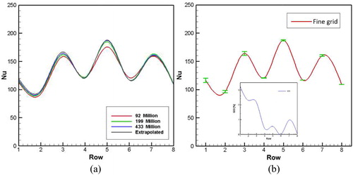
For the calculation model, the commercial software ANSYS ICEM CFD 16.0 is adopted to generate the structured mesh. In the verification, a grid convergence method called the GCI method from Ref. [Citation28] is used to accomplish the mesh validation. Three sets of meshes are conducted in this section to check the grid sensitivity, and the grid numbers are 0.92 million, 1.99 million, and 4.33 million, respectively. The mesh is refined in three coordinate directions with the ratio of 1.3. A comparative study of the area-averaged Nusselt number distribution on the endwall is carried out to obtain the difference between the predicted results by three different meshes and the extrapolated one. It can be seen that the effect of the mesh size is negligible on the results when the grid number exceeds 4.33 million. shows the discretization difference between the fine mesh with the grid number 4.33 million and the extrapolated mesh. From the figure, the red curve presents the row-averaged Nusselt number on the endwall surface by the fine mesh, while the blue one displays the detailed difference values between the fine mesh and the extrapolated one. It could be noted that the predicted results by the mesh with the grid number 4.33 million approaches the results by the extrapolated one in a good manner. Consequently, the mesh with the grid number 4.33 million is utilized to perform all the calculations in this article.
Figure 3. Comparison of row-averaged Nu along the streamwise direction for (a) three grids and (b) fine grid solution with discretization error bars.
In addition, in this article, the shear stress transport (SST) k−w turbulence model is adopted to obtain all the predictions, and to meet the requirements of the turbulence model, the values of y+ on the target walls are kept less than 1.
2.4. Numerical method validation
Due to the lack of the experimental data for mist/air cooling in the pin-finned internal channel, the numerical method is only validated for air-only cooling in this part. In the investigation, the CFD simulations are performed with identical geometrical structures and similar boundary conditions as in the experiments from Ref. [Citation12]. All calculation cases are carried out by the commercial software ANSYS CFX 16.0, in which the fully implicit coupled technique has been adopted and developed. In the validation, four turbulence models, including the SST k−w, standard k−w, standard k−ε, and BSL turbulence models, are utilized to predict the numerical results. presents the comparison of the row-averaged Nusselt numbers between the results calculated by the four turbulence models and the experimental data [Citation12]. As shown in the figure, among all the turbulence models, the standard k−ε turbulence model totally fails to capture the change trend of the row-averaged Nusselt numbers along the streamwise direction. Moreover, for the other three turbulence models, the BSL turbulence model seems fail to predict the changing trend in the last few rows. It shows relatively worse prediction compared to the SST k−w and standard k−w turbulence models. Besides, for the SST k−w and standard k−w turbulence models, the values of the row-averaged Nusselt numbers are slightly underestimated, but the differences are within the acceptable range considering the experimental uncertainty. The results predicted by the SST k−w turbulence model approach the experimental data most precisely and the errors are minimum. Therefore, all the cases in this article are calculated by adopting the SST k−w turbulence model which is satisfactory to predict the heat transfer characteristics in the pin-finned channel.
Figure 4. Comparison of the CFD predicted results by four turbulence models with measurements [Citation12].
![Figure 4. Comparison of the CFD predicted results by four turbulence models with measurements [Citation12].](/cms/asset/0de3afcb-352c-4ed4-8e61-afa3c0fa1575/unht_a_1586426_f0004_c.jpg)
When it comes to mist/air cooling, the numerical methods are more complicated because the coolant is two-phase flow. For mist/air, it consists of water droplets and a variable composition mixture of gas. Therefore, for all cases of mist/air cooling, the Eulerian-Lagrangian particle tracking method is applied. When simulating flow structure of mists, the Lagrangian method is adopted because the mass fraction of water droplets is quite small and can be treated as the discrete phase. For the main fluid, the Eulerian method is used to simulate the continuous fluid. Besides, the fully coupling is adopted when considering the effects between water liquid and the main fluid. In the calculations, the effect of mists on the continuous phase is treated as source terms in the momentum, mass, energy, and species equations. The CFD methodology and the governing equations of both discrete and continuous phases can be found in Refs. [Citation24, Citation26], which are not going to be repeated here.
2.5. Parameter definition
The Reynolds number Re is defined as,
(1)
(1)
where, ρ is the coolant density, U the inlet bulk mean velocity, D the hydraulic diameter of the unobstructed cross-section, and μ the coolant dynamic viscosity.
The local Nusselt number, Nu, is expressed as,
(2)
(2)
and the area-averaged Nusselt number, Nuave, is calculated by,
(3)
(3)
where, qw is the wall heat flux, h is the heat transfer coefficient, Tw is the local wall temperature, Tf is the mass-weighted average flow temperature, and λ is the thermal conductivity.
The value Nu0 is from the Dittus-Boelter correlation written as,
(4)
(4)
Heat transfer enhancement is always accompanied with pressure loss in the system. The definition of the friction factor reads,
(5)
(5)
where Δp is the pressure loss, and L is the length of the heated region of the internal channel.
The overall friction factor is normalized by the corresponding data for fully developed flow in a smooth channel,
(6)
(6)
The assessment of the comprehensive performance for a pin-fin array considering both heat transfer and pressure loss is given by the thermal performance factor,
(7)
(7)
3. Results and discussion
3.1. Comparison of Nusselt numbers between air-only and mist/air cooling
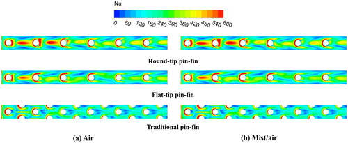
In this section, the difference of the cooling effects by air-only cooling and mist/air cooling is investigated. The initial mist temperature of 300 K, the initial mist diameter of 10 μm and the initial mist velocity of 1.0Va are studied. presents the heat transfer enhancement on the upper endwall surface for air-only cooling and mist/air cooling at a Reynolds number of 40,000. A difference of the Nusslet number distributions can be observed for different coolants, air and mist/air. As illustrated, the heat transfer performance on the endwall is slightly increased with mist/air, compared to air. This reason for the improvement can be found in Ref [Citation29]. Different from the pure coolant, air, the injection of mists bring additional advantages. First, mass transfer might happen all along the channel due to different vapor concentrations between the mainstream and the water droplet surface, which would enhance the turbulence intensity. Second, the water droplets in the thermal layers might go through a series of phase changes, like formation, growth, and separation of vapor bubbles, and all the processes will increase the flow turbulence especially near the endwall surface. Last but not the least, the latent heat of the liquid water evaporation will make a contribution to the reduction of the mainstream temperature which can remove more heat from the channel. Besides, it can be seen that for almost all the pin-finned internal channels, around the third row, the highest Nusselt number can be observed. That is because of the staggered arrangement of pin-fins in the channel. When the flow enters the channel and impinges on the first row, the blockage will disturb the flow structure which can significantly enhance the turbulence intensity. For the staggered arrangement, the second row is another first row to some extent, so the mixing mechanism is similar and the turbulence intensity can be further increased. As the flow continues moving downstream, the flow and heat transfer will reach its developed regime. Therefore, the peak of the heat transfer performance occurs around the third row. Moreover, among all the pin-fin structures, the round-tip pin-fin can achieve the best heat transfer performance.
Figure 5. Local Nusselt number contour distributions for different pin-fin structures at Re = 40,000.
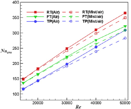
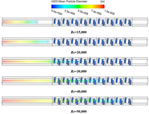
depicts the area-averaged Nusselt numbers on the upper endwall against Reynolds numbers with different coolants, air and mist/air. In these cases, the droplet temperature and diameter are 300 K and 10 µm, respectively. As shown in the figure, at relatively low Reynolds numbers of 15,000 and 20,000, the improvement of the heat transfer enhancement is not obvious with mist/air cooling, compared with air-only cooling. This is because most water droplets have been evaporated before entering into the heated portion of the channel due to the low velocity which can be observed in . As mentioned before, the evaporation of water droplets can make a contribution to the increase of the coolant mass flow rate and the decrease of the main flow temperature. However, because the mass flow rate of mists is quite a small amount, just 1% of the main flow mass flow rate, the effect of mists is weakened. With increasing Reynolds number, more water droplets can survive in the heated portion, which will have a significant impact on the enhancement of the flow turbulence intensity. At the highest Reynolds number of 50,000 in the studied range, the difference of the heat transfer rate between mist/air cooling and air-only cooling is biggest, and can reach up to 4.6% for the round-tip pin-fin structure. Based on the distributions of the area-averaged Nusselt numbers against Reynolds numbers for different coolants, another piece of important information can be obtained. The heat transfer improvement for mist/air cooling is dominated by the flow disturbance caused by mists.
Figure 6. Variation of averaged Nusselt number with Reynolds number for different pin-fin structures with different coolants.
The row-averaged Nusselt numbers on the upper endwall of the round-tip pin-finned channel with air-only cooling and mist/air cooling at the Reynolds numbers of 20,000 and 40,000 are displayed in . It is worth to mention that for the row-averaged Nusselt numbers, the calculation region centered at the pin-fin axis spans from one half longitudinal spacing upstream to another half longitudinal spacing downstream. Consistent with the analysis before, the row-averaged Nusselt number reaches its peak in the third row because of the enhanced mixing and turbulence production when the coolant flows through the first two rows and then comes into a developed state. Besides, it can be seen that at a relatively low Reynolds number of 20,000, the differences of row-averaged Nusselt numbers between air-only cooling and mist/air cooling are not very obvious. This can be explained by the evaporation of mists shown in . As mentioned before, only a small amount of mists could survive in the heated portion and it cannot progress far in the channel because most water droplets might evaporate in the unheated portion before going into the pin-finned region. However, at a relatively high Reynolds number of 40,000, more mists can survive in the heated region and go forward further, and that is the reason why the row-averaged Nusselt numbers of mist/air cooling are obviously higher than those of air-only cooling.
Figure 7. Variation of row-averaged Nusselt number for different coolants at Re = 20,000 and 40,000.
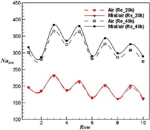
Figure 8. The droplet diameter variation with Reynolds number for mist/air cooling.
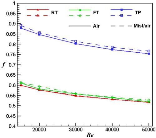
illustrates how the friction factors of the three different pin-finned channels vary with Reynolds number for air-only cooling and mist/air cooling. It can be concluded that for all the pin-fin structures, the friction factor decreases gradually with increasing Reynolds number, and this is because the velocity of the main flow increases gradually. Besides, among all the pin-fin structures, the traditional one with full attachment has the highest friction factor, and it is far higher than those for the other two pin-fin structures with detachment, because the detachment would form less resistance for the main flow. The friction factor of the flat-tip pin-fin structure is slightly higher than that of the round-tip pin-fin structure, and this is due to the fact that compared to the smooth round-tip curve, the sharp edge of the flat tip will induce relatively more dissipation. Furthermore, the friction factor seems insensitive to the coolant, and for air-only cooling and mist/air cooling, the friction factors are almost identical because the portion of mists are so small compared to the mass flow rate of the main flow, that is, the mass flow ratio is just 1%.
Figure 9. Variation of friction factors with Reynolds number for different pin-fin structures with different coolants.
3.2. Effect of initial mist temperature on heat transfer
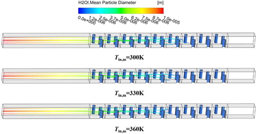
In order to investigate the influence of the initial mist temperature on the heat transfer performance of mist/air cooling in the pin-finned channels, the mist velocity of 1.0Va and the water droplet diameter of 10 μm are considered in this section. In , the trajectories of water droplets colored by diameters in the round-tip pin-finned channel are shown for the initial mist temperature range from 300 K to 360 K at a Reynolds number of 40,000. It can be seen that with increasing temperature of mists, the dissipation speed of water droplets increases gradually, which means that the survival time of water droplets decreases gradually. For the case with Tm = 300K, water droplets move forward to the longest distance, followed by the cases with Tm = 330K and Tm = 360K, respectively. This can be explained by the fact that as the initial mist temperature increases, the time period for water droplets to reach the evaporation point will be shortened, which means the evaporation rate of mists will increase before entering the heated portion, and the flow distance will decrease even for the water droplets which survive in the pin-finned region.
Figure 10. The droplet diameter variation with different initial mist temperature.
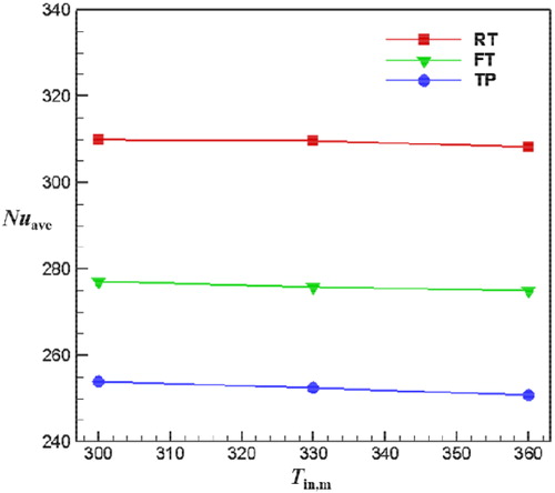
provides the comparison of the area-averaged Nusselt numbers on the upper endwall surface with three different initial mist temperatures, Tm = 300K, 330K, and 360K for different pin-fin structures at a Reynolds number of 40,000. It can be seen that for all the three pin-fin structures, the trends of the area-averaged Nusselt numbers with initial mist temperature are similar. With increasing mist temperature, the heat transfer enhancement is gradually weakened. The reason can be found in the analysis of the water droplet trajectories above. The lower the mist temperature is, the longer distance water droplets can move forward, which means that the heat transfer enhancement is dominated by the two-phase coolant for relatively longer time. Besides, consistent with the discussion before, the round-tip pin-fin has the best heat transfer performance among all structures. However, it seems that among all the three pin-fin structures, the round-tip pin-fin has the lowest reduction rate within the studied range of the initial mist temperature, while the traditional pin-fin has the highest one. This can be plausibly explained by the fact that the detachment induced by the round-tip pin-fin and the flat-tip pin-fin makes a significant contribution to the improvement of the turbulent level, which makes the advantages brought by mists relatively less.
Figure 11. Variation of averaged Nusselt number with different initial mist temperature for different pin-fin structures.
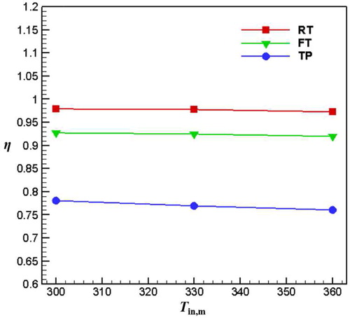
To further access the comprehensive heat transfer capability, the variations of the thermal performance factor for different pin-fin structures with the initial mist temperature are presented in . According to the definition, the thermal performance factor takes into account the heat transfer enhancement and the additional pressure loss. It is found that the thermal performance factor of the round-tip pin-finned channel is highest, because it has the highest averaged Nusselt number and the lowest pressure loss. The biggest difference between the round-tip pin-fin structure and the traditional pin-fin can reach 22.95% at the initial mist temperature of 360K. Consistent with the analysis before, for all the structures, the case with the initial mist temperature of 300K has the highest thermal performance factor, followed by the cases with the mist initial temperatures of 330K and 360K, respectively. For the round-tip pin-fin structure, the flat-tip pin-fin structure and the traditional pin-fin structure, the reduction rates of the thermal performance factors are 0.46%, 0.76%, and 1.29%, respectively.
Figure 12. Variation of thermal performance factors with different initial mist temperature for different pin-fin structures.
3.3. Effect of initial mist diameter on heat transfer
To explore the effect of the initial diameter of mists on the heat transfer performance of the internal pin-finned channels, the initial mist temperature of 300K and the mist velocity of 1.0Va are studied in this section. In , the area-averaged Nusselt number distributions on the endwall surface for different pin-finned channels are illustrated within the studied range from 5 μm to 20 μm. It can be observed the water droplet diameter has an obvious influence on heat transfer. Also, it can be seen that for all the three pin-fin structures, within the whole range of the mist diameter, the round-tip pin-finned channel achieves the best heat transfer performance, followed by the flat-tip pin-finned channel and traditional pin-finned channel. Compared to the case of the traditional pin-finned channel, the maximum differences are 8.65% and 21.88%, respectively, for the cases of round-tip pin-finned channel and flat-tip channel. For all the cases, as the water droplet diameter increases, the area-averaged Nusselt number increases first and then decreases sharply, and the heat transfer rate achieves its peak at the droplet diameter of 15 μm. This can be explained by , which captures the trajectories of water droplets in the round-tip pin-finned channel for different mist diameters at a fixed Reynolds number of 40,000. From this figure, it can be noted that as the droplet diameter increases, water droplets can proceed in the channel for relatively longer distance. For the case with the small mist diameter of 5 μm, the heat transfer is dominated by convection of the single phase coolant because most water droplets evaporate before entering the pin-finned channel. However, for the cases with medium mist diameters of 10 μm and 15 μm, part of water droplets survive in the pin-finned channel, which will effectively induce interaction between the main flow and water droplets and lead to a disturbance in the main flow. Therefore, the heat transfer performance is obviously enhanced on the endwall when the mist diameter exceeds 10 μm. Nevertheless, as the mist diameter keeps increasing, the heat transfer rate decreases instead. This can be explained in two aspects. On one hand, the specific surface area is smaller for the water droplet of larger size, which reduces the evaporation rate of water droplets and weakens the effect of the interaction, resulting in a decrease in the main flow turbulence improvement. On the other hand, a large amount of water droplets will survive in the exit region of the channel due to the low evaporation rate, which implies the usage of the latent heat of evaporation is low in such a case.
Figure 13. The droplet diameter variation with different initial mist diameter.
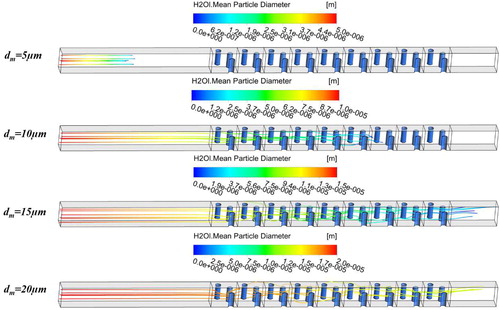
Figure 14. Variation of averaged Nusselt number with different initial mist diameter for different pin-fin structures.
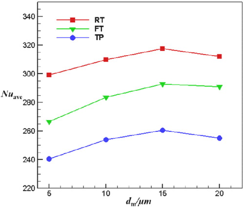
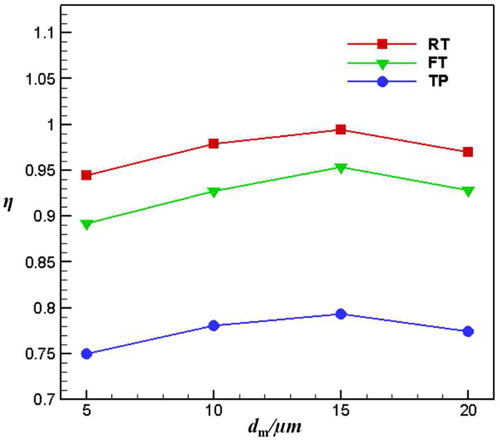
gives the variation of the thermal performance factor for different pin-fin structures for different initial mist diameters. For all cases, the thermal performance factors of the round-tip pin-finned channel are highest within the studied mist diameter range from 5 μm to 20 μm, and the maximum differences can be up to 4.31% and 25.40%, respectively, compared to flat-tip pin-finned channel and traditional pin-finned channel. Over all, the thermal performance factor of the case with the mist diameter of 15 μm is highest, followed by the cases with mist diameters of 20 μm, 10 μm, and 5 μm, respectively. From the analysis before, the heat transfer enhancement presents an increasing trend for the droplet diameter ranging from 5 μm to 15 μm, and then degrades for a droplet diameter larger than 15 μm. Also, due to the small amount of water droplets, the variation of mist diameter should have a small impact on pressure loss, and this is the reason why the distributions of the thermal performance factors are similar to those of the area-averaged Nusselt numbers.
Figure 15. Variation of thermal performance factors with different initial mist diameter for different pin-fin structures.
3.4. Effect of initial mist velocity on heat transfer
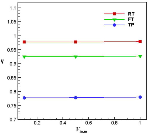
To discuss the impact of the initial mist velocity on heat transfer, the initial mist temperature of 300 K and the water droplet diameter of 10 μm are utilized in this portion, and three velocities are considered, Vm=0.1Va, 0.5Va, 1.0Va.
and show the area-averaged Nusselt numbers on the endwall and the thermal performance factors for the three different pin-fin structures respectively with different mist velocities. It is clear that for all the mist initial velocities, the area-averaged Nusselt number on the endwall of the round-tip pin-finned channel is the highest among all the structures. However, by taking a look at an individual pin-fin structure, within all the studied range of the initial mist velocity, the area-averaged Nusselt number seems to change just marginally. With increasing mist velocity, the heat transfer rate increases slightly, and that can be explained by , which presents the effect of initial mist velocity on the trajectories of water droplets. It can be seen that the flow distance of water droplets seems to be a little longer with the increase of the initial mist velocity, but the effect of the initial mist velocity is not very obvious, especially compared to the initial mist temperature and diameter. That is attributed to the fact that the initial mist diameter studied here is relatively small, dm = 10 μm, which means that water droplets are easily carried to move forward by the main flow. Therefore, the effect of the initial mist velocity on the heat transfer enhancement of the internal cooling channel is almost negligible.
Figure 16. The droplet diameter variation for different initial mist velocity.
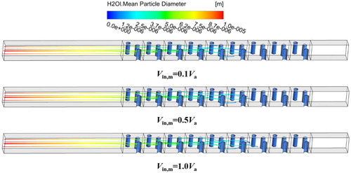
Figure 17. Variation of averaged Nusselt number for different initial mist temperature for different pin-fin structures.
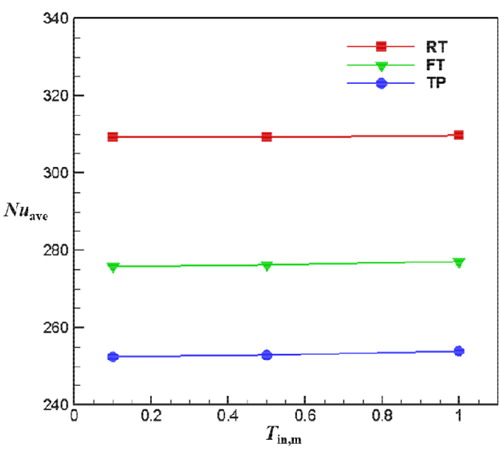
Figure 18. Variation of thermal performance factors with different initial mist velocity for different pin-fin structures.
4. Conclusions
In this study, a numerical simulation has been carried out to investigate the effects of the droplet characteristics on the heat transfer performance for three different pin-fin structures, the traditional pin-fin, flat-tip pin-fin, and round-tip pin-fin, with mist/air cooling. SST turbulence model is validated against the experimental data and achieves the best agreement. First, the difference between air-only cooling and mist/air cooling on the heat transfer enhancement of the pin-finned channels is compared, and then the effects of the initial mist temperature, diameter, and relative velocity are discussed in detail. The main conclusions are drawn as below:
Among all the three different pin-fin structures, for all calculations, the round-tip pin-fin shows the best heat transfer performance, followed by the flat-tip pin-fin and the traditional pin-fin, respectively. Besides, the traditional pin-fin with full attachment has the highest friction factor, much higher than the pin-fins with detachment, and the friction factor of the flat-tip pin-fin is slightly higher than that of the round-tip pin-fin.
The comparison between air-only cooling and mist/air cooling reveals that at relatively low Reynolds numbers of 15,000 and 20,000, the difference of the averaged Nusselt number for mist/air cooling and air-only cooling is very small, but when Reynolds number exceeds 30,000, the heat transfer enhancement for mist/air cooling is noticeably increased as compared to air-only cooling because a large amount of water droplets can survive in the pin-finned region.
As the initial mist temperature increases, the droplet travel distance and Nusselt number of mist/air cooling decrease instead and this is because the required time for the droplets to reach the evaporation point is shortened which weakens the effect of mists, leading to lower turbulence intensity improvement.
Within the studied range of the initial mist diameter from 5 μm to 20 μm, the variation of the heat transfer rate does not have a monotonic relationship with the initial mist diameter. The Nusselt number ascends gradually and then descends sharply as the initial mist diameter increases and the heat transfer coefficient achieves a peak at the initial mist diameter of 15 μm.
Due to the small diameter, the droplet movement and its flow distance are almost insensitive to the initial mist velocity, resulting in the heat transfer enhancement nearly independent of the initial mist velocity.
| Nomenclature | ||
| A | = | Area [m2] |
| C | = | Detachment of pin-tip to endwall [m] |
| d | = | Mist diameter [μm] |
| D | = | Duct hydraulic diameter [m] |
| Dh | = | Pin-fin tip diameter [m] |
| D0 | = | Pin-fin cylindrical structure diameter [m] |
| f | = | Friction factor |
| h | = | Heat transfer coefficient [W/(m2·K)] |
| H | = | Channel height [m] |
| MRF | = | Mass flow rate |
| L | = | Length [m] |
| Nu | = | Nusselt number |
| p | = | Pressure [Pa] |
| Pr | = | Prandtl number |
| q | = | Heat flux [W/m2] |
| Re | = | Reynolds number |
| S | = | Inter-pin spacing in traverse direction [m] |
| T | = | Temperature [K] |
| Tu | = | Turbulence intensity |
| U | = | Bulk mean air velocity in a channel [m/s] |
| V | = | Velocity [m/s] |
| X | = | Inter-pin spacing in longitudinal direction [m] |
| Greek Symbols | ||
| η | = | Thermal performance |
| λ | = | Thermal conductivity of fluid [W/m·K] |
| μ | = | Dynamic viscosity [N·s/m2] |
| ρ | = | Density [kg/m3] |
| Subscripts | ||
| a | = | Air |
| ave | = | Area-averaged |
| f | = | Flow |
| m | = | Mist |
| in | = | Inlet |
| o | = | Outlet |
| r | = | Row-averaged |
| w | = | Wall |
| 0 | = | Smooth channel/stagnation parameter |
Additional information
Funding
References
- D. E. Metzger, R. A. Berry, and J. P. Bronson, “Developing heat transfer in rectangular ducts with staggered arrays of short pin fins,” J. Heat Transfer, vol. 104, no. 4, pp. 700–706, 1982. DOI: 10.1115/1.3245188.
- J. Armstrong, and D. Winstanley, “A review of staggered array pin fin heat transfer for turbine cooling applications,” J. Turbomach., vol. 110, no. 1, pp. 94–103, 1988. DOI: 10.1115/1.3262173.
- R. Matsumoto, S. Kikkawa, and M. Senda, “Effect of pin fin arrangement on endwall heat transfer,” JSME Int. J. Ser. B Fluids Thermal Eng., vol. 40, no. 1, pp. 142–151, 1997. DOI: 10.1299/jsmeb.40.142.
- M. Tahat, Z. H. Kodah, B. A. Jarrah, and S. D. Probert, “Heat transfers from pin-fin arrays experiencing forced convection,” Appl. Energy, vol. 67, no. 4, pp. 419–442, 2000. DOI: 10.1016/S0306-2619(00)00032-5.
- T. Horbach, A. Schulz, and H. J. Bauer, “Trailing edge film cooling of gas turbine airfoils—external cooling performance of various internal pin fin configurations,” J. Turbomach., vol. 133, no. 4, pp. 041006, 2011. DOI: 10.1115/1.4002964.
- M. K. Chyu, C. H. Yen, and S. Siw, Comparison of Heat Transfer from Staggered Pin Fin Arrays with Circular, Cubic and Diamond Shaped Elements, ASME Paper, GT2007-28306, 2007.
- S. C. Siw, M. K. Chyu, and M. A. Alvin, Heat transfer enhancement of internal cooling passage with triangular and semi-circular shaped pin-fin arrays, ASME Paper, No. GT2012, vol. 69266, 2012.
- M. A. Moon, and K. Y. Kim, Heat transfer performance of a new fan-shaped pin-fin in internal cooling channel, ASME Paper, No. GT2013-94193, 2013.
- R. J. Goldstein, and S. B. Chen, “Flow and mass transfer performance in short Pin-Fin channels with different fin shapes,” Int. J. Rotat. Mach., vol. 4, no. 2, pp. 113–128, 1998. DOI: 10.1155/S1023621X98000104.
- J. Krueckels, S. Naik, A. Lerch, and A. Sedlov, Heat transfer in a vane tailing edge passage with conical pins and pin-turbulator integrated configurations, ASME Paper, No. GT2014-25522, 2014.
- S. C. Arora, and W. Abdel-Messeh, Characteristics of partial length circular pin fins as heat transfer augmentators for airfoil internal cooling passages, ASME Paper, No. 89-GT-87, 1989.
- S. C. Siw, M. K. Chyu, and M. A. Alvin, Effects of pin detached space on heat transfer and pin-fin arrays, ASME Paper, No. GT2010-23227, 2010.
- S. C. Siw, Chyu, M. K. Chyu, and M. A. Alvin, Effects of pin detached space on heat transfer in a rib-roughened channel, ASME Paper, No. GT2011-46078, 2011.
- J. C. Corman, H Gas turbine combined cycle technology and development status, ASME Paper, No. 96-GT-011, 1996.
- L. Shui, J. Gao, X. Shi, and J. Liu, “Effect of duct aspect ratio on heat transfer and friction in steam-cooled ducts with 60 angled rib turbulators,” Exp. Thermal Fluid Sci., vol. 49, pp. 123–134, 2013. DOI: 10.1016/j.expthermflusci.2013.04.010.
- J. Liu, J. Gao, and T. Gao, An experimental investigation of heat transfer characteristics in a steam cooled square channel with rib turbulators, ASME paper, No. GT2011-46134, 2011.
- J. Liu, J. Gao, T. Gao, and X. Shi, “Heat transfer characteristics in Steam-Cooled rectangular channels with two opposite rib-roughened walls,” Appl. Thermal Eng., vol. 50, no. 1, pp. 104–111, 2013. DOI: 10.1016/j.applthermaleng.2012.05.003.
- T. Wang, J. L. Gaddis, and X. Li, “Mist/steam heat transfer of multiple rows of impinging jets,” Int. J. Heat Mass Transfer, vol. 48, no. 25-26, pp. 5179–5191, 2005. DOI: 10.1016/j.ijheatmasstransfer.2005.07.016.
- T. Gao, J. Zeng, J. Li, and J. Gong, “Effect of aspect ratio on the flow and heat transfer characteristics of mist/steam in rectangular ribbed channels,” Num. Heat Transfer A Appl., vol. 70, no. 6, pp. 895–909, 2017.
- T. Wang, and X. Li, “Mist film cooling simulation at gas turbine operating conditions,” Int. J. Heat Mass Transfer, vol. 51, no. 21-22, pp. 5305–5317, 2008. DOI: 10.1016/j.ijheatmasstransfer.2008.04.040.
- T. S. Dhanasekaran, and T. Wang, “Simulation of mist film cooling on rotating gas turbine blades,” ASME J. Heat Transfer, vol. 134, no. 1, pp. 011501, 2012. DOI: 10.1115/1.4004480.
- L. Zhao, and T. Wang, “An experimental study of mist/air film cooling on a flat plate with application to gas turbine airfoils—part I: Heat transfer,” J. Turbomach., vol. 136, no. 7, pp. 071006, 2014. DOI: 10.1115/1.4025736.
- L. Zhao, and T. Wang, “An experimental study of mist/air film cooling on a flat plate with application to gas turbine airfoils—part II: Two-phase flow measurements and droplet dynamics,” J. Turbomach., vol. 136, no. 7, pp. 071007, 2014. DOI: 10.1115/1.4025738.
- J. Zhou, X. Wang, J. Li, and H. Lu, “CFD analysis of mist/air film cooling on a flat plate with different hole types,” Num. Heat Transfer A Appl., vol. 71, no. 11, pp. 1123–1140, 2017. DOI: 10.1080/10407782.2017.1337994.
- J. Wang, Q. Li, B. Sunden, J. Baleta, and M. Vujanovic, “Two-phase flow simulation of mist film cooling with deposition for various boundary conditions,” Num. Heat Transfer A Appl., vol. 71, no. 9, pp. 895–909, 2017. DOI: 10.1080/10407782.2017.1326790.
- X. Wang, F. Zhang, D. Zheng, and J. Li, “Effect of droplet characteristics and rotation speed on the flow and heat transfer characteristics of mist/air cooling in a rotating ribbed two-pass rectangular channel,” J. Power Energy, vol. 231, no. 2, pp. 119–132, 2017. DOI: 10.1177/0957650916680933.
- L. Ye, Z. Liu, C. Gao, X. Yang, and Z. Feng, Numerical study on heat transfer performance of a new-proposed pin-fin in an internal channel, ASME Paper, No. GT2017-64573, 2017.
- P. J. Roache, “Perspective: a method for uniform reporting of grid refinement studies, ASME,” J. Fluids Eng., vol. 116, no. 3, pp. 405–413, 1994. DOI: 10.1115/1.2910291.
- X. Li, J. L. Gaddis, and T. Wang, “Modeling of heat transfer in a mist/steam impinging jet,” ASME J. Heat Transfer, vol. 124, no. 6, pp. 1086–1092, 2001. DOI: 10.1115/1.1409262.