
 ?Mathematical formulae have been encoded as MathML and are displayed in this HTML version using MathJax in order to improve their display. Uncheck the box to turn MathJax off. This feature requires Javascript. Click on a formula to zoom.
Abstract
The field synergy principle has three criteria to qualitatively describe the essence of single-phase convective heat transfer enhancement. However, in practice these criteria are difficult to be applied to convective heat transfer analysis, because there are no corresponding indicators available to quantitatively describe them. Therefore, a unified formula for the field synergy principle was developed based on these three criteria using probabilistic techniques in this study to overcome these defects. The formula is applicable to incompressible flows with constant properties in both laminar and turbulent flow regimes. The formula contains three categories of non-dimensional indicators corresponding to the three criteria of the field synergy principle, respectively, including domain-averaged cosine of synergy angle, the Pearson linear correlation coefficients between the scalar functions contained in the energy governing equation of convective heat transfer, and the variation coefficients of these functions. The physical meanings of these indicators for the field synergy principle and their connections with the known heat transfer enhancing mechanisms were then discussed. Based on this formula, an improved analytical system for the field synergy principle was proposed. It allows an efficient and quantitative analysis of all single-phase constant-property convective heat transfer phenomena. This new system overcomes the limitation of the conventional field synergy analytical system that mainly analyzes convective heat transfer mechanism from the perspective of synergy angle.
1. Introduction
The objective of heat transfer enhancement technology is to increase the heat transfer rate under the constraints of pumping power and/or heat exchanging space [Citation1–2]. Since the 1970s, increasing concerns and economic investments have been devoted to this area [Citation3–5], and this trend is continuing. The mechanism of convective transfer enhancement is traditionally explained qualitatively from different aspects [Citation6–8], such as mixing of the fluid between the wall and core region [Citation9], reduction of thermal boundary layer thickness [Citation10], increase of turbulent flow intensity [Citation11–12], etc. An analytical tool that could provide unified and quantitative explanations of all convective heat transfer phenomena is crucial to promote the development of convective heat transfer enhancement technology. To achieve this goal, a unified theory was proposed [Citation13] to reveal the essence of heat transfer enhancement, which is called the field synergy principle (FSP). The FSP was later detailed specifically as three general criteria [Citation14], and extended from parabolic flow to elliptic flow [Citation15], and from incompressible flow to compressible flow [Citation16]. Generally, the most-frequently-used FSP analytical system (referred to as the conventional FSP hereafter) mainly uses the synergy angle as a primary indicator of synergy degree to analyze the mechanism of convective heat transfer enhancements, and its main viewpoint is that a smaller synergy angle could result in a larger Nusselt number (Nu), when the Reynolds number (Re) and Prandtl number (Pr) are fixed. Many literatures regarding the applications of the conventional FSP analytical system have been published in the recent decades. For example, Tao et al. [Citation17] observed that the single-phase convective heat transfer enhancement in the laminar flow regime could be explained from the perspective of the FSP. He et al. [Citation18] conducted parameter studies on the heat transfer characteristics of finned tube banks using a laminar flow model. The design rule for slotted fins, “front coarse, rear dense”, was explained as the improved synergy in the rear part of the fin. Shen and Liu [Citation19] studied the convective heat transfer characteristics of unsaturated porous media with the guidance of the FSP, and they found that a smaller synergy angle produces stronger heat transfer when the product of the magnitudes of the temperature gradient and velocity vector is constant. Cheng et al. [Citation20] applied the FSP to heat transfer analysis of a three-dimensional (3-D) rectangular channel with flush-mounted heat sources in the laminar flow regime. Chen et al. [Citation21] introduced three field synergy numbers for heat, mass and momentum transfer, respectively. Besides, the conventional FSP was successfully applied in mechanism analysis of lithium ion battery [Citation22], longitudinal vortices [Citation23–26], tube with twisted tape [Citation27] and heat exchangers [Citation28–30], etc.
The aforementioned literature survey shows that the conventional FSP was well applied to convective heat transfer analysis [Citation31]. However, the conventional FSP was reported to be not applicable in some cases. For example, in the laminar flow regime, Tao et al. [Citation32] carried out numerical studies on the heat transfer characteristics of wavy fin heat exchangers. They observed that the domain-averaged Nu does not always increase as expected with decreasing domain-averaged synergy angle. Guo et al. [Citation33] observed that the synergy number Fc is more appropriate to represent the synergy degree than the synergy angle. In the turbulent flow regime, the conventional FSP analytical system performs rather unsatisfactorily. Habchi et al. [Citation26] studied three duct flow configurations using the FSP, and they observed that the local synergy angle cannot characterize the local Nu. Zhu et al. [Citation34] studied the relation between the local-average-weight synergy angle and the local Nu in two-parallel plates with irregular boundary conditions, and it was observed that the domain-averaged synergy angle in the cross section cannot reflect the variations of local Nu.
Overall, the limitations of the conventional FSP analytical system can be summarized as the following three aspects, which hinder the broad applications of this theory to convective heat transfer analysis. Equation(1)(1)
(1) Except the criterion relative to synergy angle, the other two criteria of the FSP are neglected, which makes the analytical result one-sided. Equation(2)
(2)
(2) Synergy angle cannot quantitatively reflect the synergy degree [Citation25], and it even fails to predict the variational trend of synergy degree in some cases [Citation31, Citation33, Citation34], especially in the turbulent flow regime. Equation(3)
(3)
(3) Although Fc can represent the overall synergy degree of a thermal-flow field, it is difficult to use as an indicator for in-depth heat transfer analysis.
To overcome these limitations, a unified formula for the FSP was developed in this study to incorporate all the three criteria into the FSP analytical system, whereby improving the performance of the FSP in convective heat transfer analysis.
2. FSP and its three criteria
2.1. Brief review of the FSP
Integrating the energy equation of a two-dimensional (2-D) flat-plate laminar flow over the thermal boundary layer leads to the following equation [Citation13]:
(1)
(1)
where
θ and
are the non-dimensional velocity magnitude, non-dimensional temperature gradient, synergy angle, and non-dimensional distance perpendicular to the wall, respectively.
By extending the integral domain of EquationEq. (1)(1)
(1) from the thermal boundary layer to the whole fluid domain [Citation11], EquationEq. (2)
(2)
(2) is obtained:
(2)
(2)
where
is the non-dimensional area.
From EquationEq. (2)(2)
(2) , it can be concluded that Nu is determined by Re, Pr and the integral term
Tao et al. [Citation17] noted that the term
is equal to Nu under fully synergy conditions (the isotherms are always perpendicular to the velocity vectors). However, Re and Pr are always constrained by operating conditions, such as the given mass flow rate, size of heat exchangers, pumping power and working fluid; thus, their potential for heat transfer enhancement is limited. An efficient way of heat transfer enhancement is to increase
i.e., the synergy number Fc (EquationEq. (3)
(3)
(3) ) [Citation15]. Fc is equal to unity under fully synergy condition and it is much smaller than unity for most convective heat transfer problems, implying that there is a large room open for convective heat transfer enhancement [Citation14].
(3)
(3)
2.2. Three criteria of the FSP
Three general criteria [Citation14] were proposed to qualitatively indicate how to increase Fc, and these provide a general insight into convective heat transfer enhancement from the perspective of field synergy. They include:
the first criterion, “the intersection angle between the velocity and the temperature gradient/heat flow should be as small as possible.”
the second criterion, “the local values of the three scalar fields should all be simultaneously large.”
the third criterion, “the velocity and temperature profiles at each cross section should be as uniform as possible”.
The first and third criteria describe the three fields’ own characteristics, while the second criterion describes the relations between the three scalar fields. Therefore, these three criteria are parallel with each other and should be simultaneously satisfied as far as possible to enhance convective heat transfer.
To achieve a substantial improvement of the performance of FSP in convective heat transfer analysis, it is imperative to quantify the three criteria with different indicators and unify these indicators into a formula for Nu. Based on this idea, a unified formula for the FSP is developed in this study.
3. Unified formula for the FSP
In this section, a non-dimensional indicator named synergy coefficient (SC) is defined to describe the synergy degree between different scalar fields, and the calculation of SC by means of a probabilistic method is subsequently provided. Then, a unified formula for the FSP is derived based on the three criteria for the FSP.
3.1. Synergy coefficient
To facilitate the formula derivation and result discussion, SC is defined in EquationEq. (4)(4)
(4) , which represents the synergy degree between different scalar function fields (such as |∇(T)|, u, cos(θ) of a flow field) in terms of achieving a high integral value of their product over a specific flow domain. It can readily be deduced from EquationEq. (4)
(4)
(4) that if each integral value of B1, B2, B3 … Bn over Ω is constant, SC (B1, B2 … Bn) should be as large as possible to get a larger
(4)
(4)
where B1, B2, B3 … and Bn are different scalar functions defined in the 3-D flow domain Ω with volume VΩ.
If we divide the 3-D domain Ω into n sub-regions and take the mean values of function B, function C and an extra function BC (the product of B and C) in each sub-region as samples of function B, function C and the extra function BC in Ω, respectively. Then three sample spaces, S (B), S (C) and S (BC), can be obtained in Ω. Assume that the probability of the sample in each sub-region is equal to the ratio of the volume of the sub-region to VΩ, and if n is large enough, it is easy to get the expected values and the variances of S (B), S (C) and S (BC) in Ω. Therefore, we have the following:
(5)
(5)
According to probabilistic knowledge, one can get the following:
(6)
(6)
where C⋅V is the variation coefficient that reflects the dispersion degree of the sample distribution in the sample space. r (B, C) is the Pearson correlation coefficient, which reflects the linear correlation degree between S (B) and S (C).
Introduce an arbitrary non-zero constant, m, into Fc, and it is easy to deduce the following equation according to EquationEq. (5)(5)
(5) .
(7)
(7)
3.2. Derivation of the unified formula
In this section, the unified formula for the FSP is derived in the 3-D fluid domain Ω. As illustrated in , Ω is surrounded by three types of boundaries that commonly exist in practice, including the wall boundaries (Sw) where convective heat transfer occurs, the other wall boundaries where convective heat transfer can be neglected, and the boundaries inside fluid where heat diffusion (λeff|∇(T)|) in the boundary normal direction can be neglected (as long as the Péclet number is greater than 100 [15]).
Figure 1. Schematic for convective heat transfer between walls and fluid.
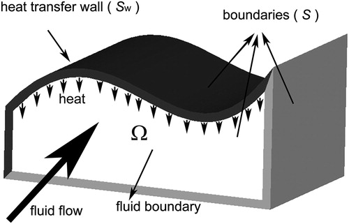
For most convective heat transfer problems encountered in practice, the following assumptions are applied: (a) steady state, (b) incompressible flow with constant fluid properties, (c) negligible viscous dissipation and flow work and (d) no internal heat sources. The scalar-form energy equation is as follows:
(8)
(8)
Integrating the energy equation over Ω, we find the following:
(9)
(9)
Using Gauss’s law to reduce the integration dimension yields the following form:
(10)
(10)
where S represents the bounding surface of the fluid domain.
Considering that heat flux qn (qn = λeff|∇(T)n|, |∇(T)n|: temperature gradient component in the normal direction of fluid boundary) diffused through the boundaries inside fluid along the normal direction can be neglected as compared with wall heat flux qw, we have the following:
(11)
(11)
where Qw represents the total heat transfer rate between the fluid and the heat transfer walls Sw.
Then, we have the following equation for the convective heat transfer coefficient hw:
(12)
(12)
where
Aw is the area of Sw.
By introducing the characteristic length L′, we obtain the following equation for Nu:
(13)
(13)
where:
λ is thermal conductivity, υ is kinematic viscosity, ρ is density, Cp is constant-pressure specific heat.
EquationEq. (13)(13)
(13) can be transferred to the following form:
(14)
(14)
Then, with the help of SC (EquationEq. (6)(6)
(6) ), three non-dimensional parameters are defined as follows:
(15)
(15)
(16)
(16)
(17)
(17)
where
is the domain-averaged cosine of the synergy angle;
and
are two parameters to facilitate the formula derivation; k′ is the correction factor required to convert the domain-averaged temperature difference
to
so that the equation can correspond with Nu which is defined by
Because
≈ (Tw−Tmin), where Tmin is the minimum fluid temperature in Ω, and (Tw−Tmin) is very close to
the value of k′ is quite close to unity.
Since the fluid properties are assumed to be constant, according to EquationEq. (8)(8)
(8) , we have:
(18)
(18)
(19)
(19)
Substituting EquationEqs. (15)(15)
(15) , Equation(16)
(16)
(16) and Equation(17)
(17)
(17) into EquationEq. (14)
(14)
(14) , we obtain the following:
(20)
(20)
Substituting EquationEqs. (18)(18)
(18) and Equation(19)
(19)
(19) into EquationEq. (20)
(20)
(20) , we obtain the unified formula for the FSP:
(21)
(21)
4. In-depth interpretation of the unified formula
In this section, we will discuss the physical meaning of the indicators involved in the unified formula for the FSP, and subsequently an improved FSP analytical system is introduced.
According to EquationEq. (3)(3)
(3) and EquationEq. (21)
(21)
(21) , we have the following:
(22)
(22)
The product of Re and Pr in EquationEq. (21)(21)
(21) can be regarded as the potential of convective heat transfer, i.e., the maximum Nu virtually achievable under the full synergy condition [Citation17]. The value of k′ is generally very close to unity, hence k′ has little influence on Nu. Thus, according to EquationEq. (22)
(22)
(22) , Fc is determined by three categories of non-dimensional indicators, including the first category:
; the second category: r (u, cos(θ)) and r (u cos(θ),
); the third category: C⋅V (u), C⋅V (cos(θ)), C⋅V (u cos(θ)) and C⋅V (
). These FSP indicators correspond to the three criteria of the FSP, respectively, and their physical explanations are presented in the following.
4.1. Indicator corresponding to the first criterion of the FSP
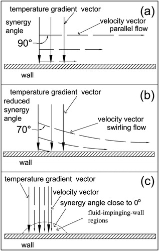
is the indicator corresponding to the first criterion of the FSP, and it may be explained as follows. As shown in ,
is quite close to zero in most cases, owing to the fact that velocity vector and temperature gradient vector are approximately parallel to and perpendicular to the heat transfer wall, respectively. However,
can be increased or decreased greatly when the flow swirls or fluctuates because of the interactions with heat transfer enhancement components, accompanying the transport of the fluid from the wall into the free stream and vice versa, as shown in . Therefore, increasing
(decreasing synergy angle) generally accompanies the enhancement of secondary flow, which may result in convective heat transfer augmentation introduced by fluid exchange between the wall and core region [Citation35]. However, enhancing fluid mixing between the wall and free stream to augment convective heat transfer is generally more effective in the laminar flow regime as compared with in the turbulent flow regime. This is because in the laminar flow regime, heat will be transferred within the fluid by pure conduction and the heat transfer capacity will be at the lowest level if there is no fluid exchange by advection in the temperature gradient direction. Therefore, synergy angle is capable of evaluating the synergy degree (i.e., Nu when Re and Pr are fixed) of convective heat transfer in the laminar flow regime. As for the case in the turbulent flow regime [Citation36–37], reducing the thermal resistance posed by the boundary layer to enhance convective heat transfer is generally considered more effective as compared with fluid mixing, because heat can be transferred effectively by local instantaneous fluid pulsation (the effective conductivity is much larger than molecular thermal conductivity) in the region away from boundary layer. This explains why the synergy-angle-based conventional FSP analytical system performs much better in the laminar flow regime than in the turbulent flow regime, which has been well presented by the literature survey in the introduction section.
Figure 2. Parallel flow, swirling flow, and jet impingement.
4.2. Indicators corresponding to the second criterion of the FSP
These indicators include r (u, cos(θ)) and r (u cos(θ), ). The Pearson correlation coefficient is used to describe the linear degree between two different data sets (groups of samples). Thus, r (u, cos(θ)) and r (u cos(θ),
) can be taken as indicators for the second criterion of FSP. This criterion can be explained as follows: generally, the fluid velocity field is much stronger in the region away from the heat transfer walls due to the existence of a boundary layer, whereas the situation is reversed for the temperature gradient field. As for the synergy angle field, the value of cos(θ) becomes close to zero in the near wall regions as the temperature vector is more perpendicular to the velocity vector. Thereby, r (u cos(θ),
) is negative in most cases. When the flow impinges on the heat transfer wall with a small angle (angle between velocity vector and wall normal direction), the local u, cos(θ) and
fields will be simultaneously strong in this fluid-impinging-wall region (), and as a result r (u cos(θ),
) will be increased along with the local reduction of the thermal boundary layer thickness and the resulting convective heat transfer enhancement. Therefore, r (u cos(θ),
) is closely related to the interaction between the fluid and heat transfer wall, and it can be used to evaluate the convective heat transfer enhancing technologies that are achieved by increasing the interaction between the wall and fluid, such as jet impingement, longitudinal vortex generator, corrugated tube, louvered fins, among others.
As for r (u, cos (θ)), it is to a great extent determined by the synergy angle field as the velocity magnitude distribution along the wall normal direction is relatively fixed. When the local cos (θ) becomes larger in the near wall regions, r (u, cos (θ)) is decreased, while r (u cos(θ), ) is increased. Therefore, r (u, cos (θ)) generally has a negative correlation with r (u cos(θ),
).
4.3. Indicators corresponding to the third criterion of the FSP
This category of FSP indicator includes C⋅V (u), C⋅V (cos(θ)), C⋅V (u cos(θ)) and C⋅V (). Variation coefficients describe the dispersion degree of a data set, and a small dispersion means a good uniformity. Therefore, they can be treated as indicators for the third criterion. Because r (u cos(θ),
) is negative in most cases, according to EquationEq. (22)
(22)
(22) , C⋅V (u cos(θ)) and C⋅V (
) should be as small as possible to enhance the heat transfer, i.e., the fields of u cos(θ) and
should be as uniform as possible. It was reported in [Citation14] that improving the uniformity of the temperature field could lead to convective heat transfer enhancement. Generally, for a specific convective heat transfer process with fixed boundary conditions, a better uniformity of the temperature gradient field (small value of C⋅V (
)) means that heat is more effectively transferred from the wall to the regions away from the walls. Therefore, the technologies based on increasing the effective conductivity of fluid, e.g., promoting turbulence intensity, adding high-thermal conductivity particles/inserts into fluid, liquid metal convection heat transfer are closely related to C⋅V (
). Concerning C⋅V (u cos(θ)), it decreases with the increase of cos(θ) in the near wall regions where the local velocity field is weak. Convective heat transfer enhancement in the hydraulic and/or thermal entry region may be related to C⋅V (u) and C⋅V (
), considering that C⋅V (u) and C⋅V (
) are very small in this region. Overall, the importance of this group of indicators for convective heat transfer enhancement needs to be further explored through much more case studies.
4.4. Improved FSP analytical system
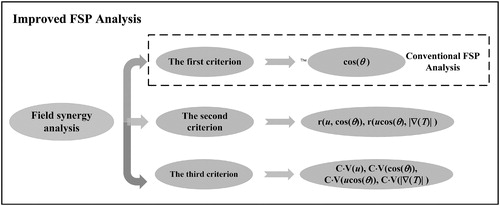
Consequently, an improved FSP analytical system to analyze the convective heat transfer mechanism is established with its analytical process schematically shown in . It provides unified and quantitative explanations for all single-phase constant-property convective heat transfer phenomena from the perspective of field synergy. Generally, for a specific convective heat transfer problem, only several of the FSP indicators have prominent effects on convective heat transfer behaviors based on their contributions to the variation of Nu, which will help us to simplify the FSP analysis. By judging which group being the most significant FSP indicator for a convective heat transfer process, this system classifies convective heat transfer enhancement technologies into three modes, including decreasing synergy angle, increasing the linear correlation coefficient between u, cos (θ) and |∇ (T)| and improving the field uniformities of u, cos (θ) and |∇ (T)|, leading to a unified understanding of all single-phase convective heat transfer phenomena. On the other hand, because this system is based on statistical indicators, its advantages in heat transfer mechanism analysis over the conventional methods would be more prominent in complex heat-flow-conjugated problems, in which the conventional methods may be difficult to apply, such as flow under complicated boundary conditions (it is difficult to make a qualitative analysis just through observing the contours of temperature, velocity or other related variables). However, it should be noted that, as a new analytical system for convective heat transfer, great efforts are required to further explore and refine this theory in the following aspects:
Figure 3. The improved FSP analytical system.
(1) Although some work has been done in this study, it needs to further clarify the physical relations of the FSP indicators through more case studies for better applications of this theory to convective heat transfer analysis.
(2) Explore the possible connections of the FSP indicators with the indicator for overall thermal-hydraulic performance and the way how to apply the analytical results to optimize convective heat transfer.
5. Conclusions
A unified formula was derived based on the three general criteria of the FSP by means of probabilistic techniques. The unified formula is applicable to incompressible flows with constant fluid properties in both laminar and turbulent flow regimes. The unified formula quantifies the three criteria of the FSP with three categories of non-dimensional indicators, including: (1) (the first criterion of the FSP); (2) r (u, cos(θ)) and r (u cos(θ),
) (the second criterion of the FSP); (3) C⋅V (u), C⋅V (cos(θ)), C⋅V (u cos(θ)) and C⋅V (
) (the third criterion of the FSP). Thus, convective heat transfer mechanism analysis can be conducted from the three aspects of the FSP quantitatively, overcoming the limitation of the conventional FSP analytical system which mainly takes the synergy angle as the primary indicator to describe the synergy degree. The improved FSP analytical system can provide unified and quantitative explanations for all single-phase constant-property convective heat transfer phenomena. As an analytical method based on statistical indicators, its merits over the conventional ones in convective heat transfer analysis will be more prominent for convective heat transfer problems under complicated boundary conditions.
| Nomenclature | ||
| A | = | area, m2 |
| Cp | = | specific heat at constant pressure, Jkg−1K−1 |
| h | = | convective heat transfer coefficient, Wm−2K−1 |
| L | = | length, m |
| qn | = | heat flux perpendicular to the wall, Wm−2 |
| Qw | = | heat transfer rate between wall Sw and fluid, W |
| S | = | the bounding surface of the fluid domain, m-2 |
| Sw | = | wall boundaries where the convective heat transfer occurs, m2 |
| T | = | temperature, K |
| u | = | velocity magnitude, ms−1 |
| u∞ | = | average velocity, ms−1 |
| V | = | volume of fluid domain, m−3 |
| Greek symbols | = | |
| θ | = | synergy angle, ° |
| λ | = | thermal conductivity, Wm−1K−1 |
| μ | = | dynamic viscosity, Pas−1 |
| ρ | = | density, kgm−3 |
| Ω | = | fluid domain |
| Non-dimensional parameters | = | |
| C·V | = | variation coefficient |
| Fc | = | synergy number, Nu/(RePr) |
| k′ | = | correlation factor of temperature difference |
| Nu | = | Nusselt number, hL/λ |
| Pr | = | Prandtl number, μCp/λ |
| Re | = | Reynolds number, ρuL/μ |
| = | Pearson correlation coefficient | |
| SC | = | synergy coefficient |
| Subscripts | = | |
| b | = | bulk |
| eff | = | effective |
| w | = | wall |
| Abbreviations | = | |
| FSP | = | field synergy principle |
Additional information
Funding
References
- B. Kundu and K. S. Lee, “A proper analytical analysis of annular step porous fins for determining maximum heat transfer,” Energy Conv. Manag., vol. 110, pp. 469–480, 2016. DOI: 10.1016/j.enconman.2015.09.037.
- M. H. Kim, H. Kim, D. R. Kim, and K. S. Lee, “A novel louvered fin design to enhance thermal and drainage performances during periodic frosting/defrosting conditions,” Energy Conv. Manag, vol. 110, pp. 494–500, 2016. DOI: 10.1016/j.enconman.2015.11.028.
- J. F. Fan, W. K. Ding, Y. L. He, and W. Q. Tao, “Three-dimensional numerical study of fluid and heat transfer characteristics of dimpled fin surfaces,” Numer. Heat Tranf. A-Appl, vol. 62, no. 4, pp. 271–294, 2012. DOI: 10.1080/10407782.2012.666931.
- R. A. Khachfe and Y. Jarny, “Numerical solution of 2-D nonlinear inverse heat conduction problems using finite-element techniques,” Numer Heat Tranf. B-Fundam, vol. 37, pp. 45–67, 2000.
- W. Wang, Y. N. Zhang, J. Liu, Z. Wu, B. X. Li, and B. Sundén, “Entropy generation analysis of fully-developed turbulent heat transfer flow in inward helically corrugated tubes,” Numer. Heat Tranf. A-Appl, vol. 73, no. 1, pp. 1–18, 2018.
- Q. W. Wang, B. Sundén, Y. T. Chen, Z. X. Guo, and P. Stehlik, “Selected papers presented at the First International Workshop on heat transfer advances for energy conservation and pollution control,” Heat Transf. Eng, vol. 35, pp. 49–550, 2014.
- X. T. Liu, G. H. Zhang, B. Sundén, and G. N. Xie, “Numerical predictions of flow and heat transfer of film cooling with an internal channel roughened by crescent ribs,” Numer. Heat Tranf. A-Appl, vol. 74, no. 9, pp. 1539–1564, 2018. DOI: 10.1080/10407782.2018.1538291.
- S. T. Wang, H. Yan, L. Luo, W. Du, B. Sundén, and X. H. Zhang, “Heat transfer characteristics of a dimpled/protrusioned pin fin wedge duct with different converging angles for turbine blades,” Numer. Heat Tranf. A-Appl, vol. 76, no. 5, pp. 369–392, 2019. DOI: 10.1080/10407782.2019.1630235.
- J. Cor Joseph. “Modeling centrifugal, multiphase, turbulent flows with a mixture-averaged drift-flux algorithm,” Numer Heat Tranf. B-Fundam, vol. 74, no. 4, pp. 647–660, 2018. DOI: 10.1080/10407790.2019.1580045.
- F. Moukalled, L. Mangani, and M. Darwish, “The characteristic boundary condition in pressure-based methods,” Numer Heat Tranf. B-Fundam, vol. 76, no. 2, pp. 43–59, 2019. DOI: 10.1080/10407790.2019.1644942.
- P. U. Ogban and G. F. Naterer, “Control volume finite element method for entropy generation minimization in mixed convection of nanofluids,” Numer Heat Tranf. B-Fundam, vol. 75, no. 6, pp. 363–382, 2019. DOI: 10.1080/10407790.2019.1627797.
- J. M. Gorman, E. M. Sparrow, J. P. Abraham, and W. J. Minkowycz, “Evaluation of the efficacy of turbulence models for swirling flows and the effect of turbulence intensity on heat transfer,” Numer Heat Tranf. B-Fundam, vol. 70, no. 6, pp. 485–502, 2016. DOI: 10.1080/10407790.2016.1244390.
- Z. Y. Guo, D. Y. Li, and B. X. Wang, “A novel concept for convective heat transfer enhancement,” Int. J. Heat Mass Transf, vol. 41, no. 14, pp. 2221–2225, 1998. DOI: 10.1016/S0017-9310(97)00272-X.
- Z. Y. Guo, W. Q. Tao, and R. K. Shah, “The field synergy (coordination) principle and its applications in enhancing single phase convective heat transfer,” Int. J. Heat Mass Transf, vol. 48, no. 9, pp. 1797–1807, 2005. DOI: 10.1016/j.ijheatmasstransfer.2004.11.007.
- W. Q. Tao, Z. Y. Guo, and B. X. Wang, “Field synergy principle for enhancing convective heat transfer––its extension and numerical verifications,” Int. J. Heat Mass Transf, vol. 45, no. 18, pp. 3849–3856, 2002. DOI: 10.1016/S0017-9310(02)00097-2.
- B. Zhang, J. S. Lv, and J. X. Zuo, “Compressible fluid flow field synergy principle and its application to drag reduction in variable-cross-section pipeline,” Int. J. Heat Mass Transf, vol. 77, pp. 1095–1101, 2014. DOI: 10.1016/j.ijheatmasstransfer.2014.06.027.
- W. Q. Tao, Y. L. He, Q. W. Wang, Z. G. Qu, and F. Q. Song, “A unified analysis on enhancing single phase convective heat transfer with field synergy principle,” Int. J. Heat Mass Transf, vol. 45, no. 24, pp. 4871–4879, 2002. DOI: 10.1016/S0017-9310(02)00173-4.
- Y. L. He, W. Q. Tao, F. Q. Song, and W. Zhang, “Three-dimensional numerical study of heat transfer characteristics of plain plate fin-and-tube heat exchangers from view point of field synergy principle,” Int. J. Heat Fluid Flow, vol. 26, no. 3, pp. 459–473, 2005. DOI: 10.1016/j.ijheatfluidflow.2004.11.003.
- S. Shen, W. Liu, and W. Q. Tao, “Analysis of field synergy on natural convective heat transfer in porous media,” Int. Commun. Heat Mass Transf, vol. 30, no. 8, pp. 1081–1090, 2003. DOI: 10.1016/S0735-1933(03)00174-X.
- Y. P. Cheng, T. S. Lee, and H. T. Low, “Numerical analysis of mixed convection in three-dimensional rectangular channel with fush-mounted heat sources based on field synergy principle,” Int. J. Numer. Methods Fluids, vol. 52, no. 9, pp. 987–1003, 2006. DOI: 10.1002/fld.1218.
- Q. Chen, M. R. Wang, and Z. Y. Guo, “Field Synergy Principle for Energy Conservation Analysis and Application,” Adv. Mech. Eng, vol. 2, pp. 1652–1660, 2010.
- H. W. He, H. Jia, W. W. Huo, and F. C. Sun, “Field synergy analysis and optimization of the thermal behavior of lithium ion battery packs,” Energies, vol. 10, no. 1, pp. 81–91, 2017. DOI: 10.3390/en10010081.
- Y. G. Lei, F. Zheng, C. F. Song, and Y. K. Lyu, “Improving the thermal hydraulic performance of a circular tube by using punched delta-winglet vortex generators,” Int. J. Heat Mass Transf, vol. 111, pp. 299–311, 2017. DOI: 10.1016/j.ijheatmasstransfer.2017.03.101.
- B. Lotfi, B. Sundén, and Q. W. Wang, “An investigation of the thermo-hydraulic performance of the smooth wavy fin-and-elliptical tube heat exchangers utilizing new type vortex generators,” Appl. Energy, vol. 162, pp. 1282–1302, 2016. DOI: 10.1016/j.apenergy.2015.07.065.
- G. F. Lu and G. B. Zhou, “Numerical simulation on performances of plane and curved winglet – Pair vortex generators in a rectangular channel and field synergy analysis,” Int. J. Therm. Sci, vol. 109, pp. 323–333, 2016. DOI: 10.1016/j.ijthermalsci.2016.06.024.
- C. Habchi, T. Lemenand, D. D. Valle, L. Pacheco, O. L. Corre, and H. Peerhossaini, “Entropy production and field synergy principle in turbulent vortical flows,” Int. J. Therm. Sci, vol. 50, no. 12, pp. 2365–2376, 2011. DOI: 10.1016/j.ijthermalsci.2011.07.012.
- Y. P. Cao, H. B. Ke, Y. S. Lin, M. Zeng, and Q. W. Wang, “Investigation on the flow noise propagation mechanism in pipelines of shell-and-tube heat exchangers based on synergy principle of flow and sound fields,” Appl. Thermal Eng, vol. 122, pp. 339–349, 2017. DOI: 10.1016/j.applthermaleng.2017.04.057.
- X. Y. Zhang, Z. X. Liu, and W. Liu, “Numerical studies on heat transfer and flow characteristics for laminar flow in a tube with multiple regularly spaced twisted tapes,” Int. J. Therm. Sci, vol. 58, pp. 157–167, 2012. DOI: 10.1016/j.ijthermalsci.2012.02.025.
- Z. Li, W. Q. Tao, and Y. L. He, “A numerical study of laminar convective heat transfer in microchannel with non-circular cross-section,” Int. J. Therm. Sci, vol. 45, no. 12, pp. 1140–1148, 2006. DOI: 10.1016/j.ijthermalsci.2006.01.011.
- S. M. Shahril, G. A. Quadir, N. A. M. Amin, and I. A. Badruddin, “Numerical investigation on the thermohydraulic performance of a shell-and-double concentric tube heat exchanger using nanofluid under the turbulent flow regime,” Numer. Heat Tranf. A-Appl, vol. 71, no. 2, pp. 215–231, 2017. DOI: 10.1080/10407782.2016.1264736.
- Y. P. Cheng, Z. G. Qu, W. Q. Tao, and Y. L. He, “Numerical design of efficient slotted fin surface based on the field synergy principle,” Numer. Heat Tranf. A-Appl, vol. 45, no. 6, pp. 517–538, 2004. DOI: 10.1080/10407780490277644.
- Y. B. Tao, Y. L. He, Z. G. Wu, and W. Q. Tao, “Three-dimensional numerical study and field synergy principle analysis of wavy fin heat exchangers with elliptic tubes,” Int. J. Heat Fluid Flow, vol. 28, no. 6, pp. 1531–1544, 2007. DOI: 10.1016/j.ijheatfluidflow.2007.02.001.
- J. F. Guo, M. T. Xu, and L. Cheng, “Numerical investigations of curved square channel from the viewpoint of field synergy principle,” Int. J. Heat Mass Transf, vol. 54, no. 17-18, pp. 4148–4151, 2011. DOI: 10.1016/j.ijheatmasstransfer.2011.03.054.
- X. W. Zhu and J. Q. Zhao, “Improvement in field synergy principle: More rigorous application, better results,” Int. J. Heat Mass Transf, vol. 100, pp. 347–354, 2016. DOI: 10.1016/j.ijheatmasstransfer.2016.05.003.
- H. Benzenine, R. Saim, S. Abboudi, O. Imine, H. F. Oztop, and N. Abu-Hamdeh, “Numerical study of a three-dimensional forced laminar flow in a channel equipped with a perforated baffle,” Numer. Heat Tranf. A-Appl, vol. 73, no. 12, pp. 881–894, 2018. DOI: 10.1080/10407782.2018.1486645.
- J. Ahn, E. M. Sparrow, J. M. Gorman, and W. J. Minkowycz, “Investigation of coupled systems consisting of fluid movers and heat-exchange devices,” Numer. Heat Tranf. A-Appl, vol. 70, no. 9, pp. 964–979, 2016. DOI: 10.1080/10407782.2016.1214480.
- J. M. Gorman, E. M. Sparrow, S. D. M. Katz, and W. J. Minkowycz, “Convective heat transfer coefficients on all external surfaces of a generic residential building in crossflow,” Numer. Heat Tranf. A-Appl, vol. 75, no. 2, pp. 71–79, 2019. DOI: 10.1080/10407782.2019.1574474.