
ABSTRACT
An in-service X80 gas pipeline was repaired with type-B sleeve. Cracks were not detected immediately after welding, but appeared on the surface of fillet weld after 2 days. Chemical composition analysis, welding pass inspection, optical microscopy, energy spectrum analysis, scanning electron microscope (SEM) and electron backscattered diffraction (EBSD) were conducted to analyse the cause of weld cracking, as well as finite element simulation of residual stress. The results showed excessive hydrogen in weld seam resulted from humidity of construction environment. Meanwhile, the thickness and width of weld bead exceeded the specification because of high heat input welding. The above reasons brought microstructure deterioration and high residual stress of fillet weld. The crack initiated from the high stress position of the fillet weld surface and fractured in transgranular quasi-cleavage mode.
Introduction
Pipeline is the most efficient way for long distance oil and gas transportation [Citation1]. Pipeline repairing is one of the most essential way to ensure stable operation of oil and gas pipeline. For the recessive defects which often appear in pipeline, i.e. wall thickness loss, deformation, girth weld defects et al., replacement of pipes costs massive time and economical loss [Citation2–4]. However, type-B sleeve welding repair is one of the most reliable maintenance methods and widely accepted [Citation5–7].
Welding quality is the fundamental guarantee for effective type-B sleeve repair. A well combination of high strength and high toughness is essential for safety of welds [Citation8–17]. According to engineering experience, cold crack resulting from material microstructure, improper structure and welding residual stress is the main factor causing weld seam failure. A large number of scholars have conducted research on the influence of weld microstructure on cold cracking sensitivity [Citation18–21]. In general, brittle hard microstructures with low plasticity are prone cold cracking. Failures related to improper structure usually combined with fatigue stress. The fillet weld crack propagation was studied and fatigue life prediction was proposed in many researches [Citation22,Citation23]. Due to the localized heat generation in welding process, residual stress is inevitable especially for thick fillet weld. The distribution pattern and influencing factors of residual stress were studied through finite element method [Citation24,Citation25].
In this study, an in-service gas pipeline was repaired with type-B sleeve, and no cracks were found immediately by non-destructive test after repairing. However, three transverse cracks appeared after two days. In the present paper, the cause of fillet weld cracking was analysed through experiments and numerical simulation.
Experimental methods
The pipe of Φ1219 mm × 15.3 mm was made of X80 grade steel, while the sleeve is made of Q345B steel, with a wall thickness of 40 mm and a width of 350 mm.
The fillet weld is manufactured through shielded metal arc welding (SMAW), and the standard welding parameters are presented in . According to the specification, type-B sleeve welding requires E5515-G welding solder which is 3.2 mm × 350 mm or 4.0 mm × 400 mm. Welding solder should be dried at 400°C for 1 h before welding. The pipeline operation pressure is 6.6 MPa and gas flow rate is 7 m/s during type-B sleeve welding. It is worth noting that heavy fog weather was encountered during the welding process, the humidity at the construction site exceeded the specification.
Table 1. Welding parameter of fillet weld.
The cracking fillet weld structure cut off from line pipe was conducted mechanical tests, microstructure analysis and residual stress simulation.
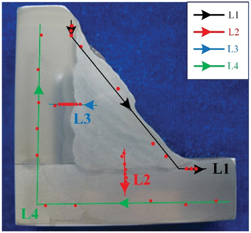
Mechanical properties of both pipe material and fillet weld were tested and compared to the specification. The tensile strength and impact toughness of pipe, as well as impact toughness and hardness of fillet weld, were tested. All the specimens were milled according to ASTM A370–2020. The tensile strength was tested according to GB/T 228.1–2020 at tensile rate of 2 mm/min. The impact toughness was measured at −10°C through Charpy impact test according to GB/T 229–2020. The Vickers hardness of fillet weld was tested along the path shown in with test force of HV10.
Figure 1. Hardness testing path of fillet weld.
The microstructure of fillet weld was polished and etched, and then observed using optical microscope (OM, Leica DM2500M) and SEM (JEOL-7200 F) to analyse the welding pass, as well as grain texture and characteristics. The cross section and fracture surface of fillet weld crack were observed and analysed through SEM, EBSD and energy dispersive spectrometer (EDS) to reveal the origin and propagation of crack.
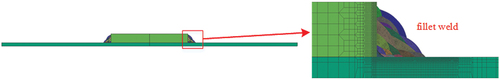
In terms of residual stress analysis of fillet weld, residual stress was physical tested through hole drilling strain-gauge method according to GB/T 31,310–2014, meanwhile the numerical simulation based on SYSWELD software was performed to verify the results. A 2D model shown in was established based on the actual model. Transitional mesh of 0.5 mm was adopted to refine the mesh of weld and welding line near line section, while coarser mesh from 1 mm to 8 mm is established away from the weld. Linear decreasing method is used to mesh the model, which can ensure both the accuracy and efficiency of calculations.
Figure 2. Finite element model.
Results and discussion
Mechanical properties
The tensile test results of X80 pipe are listed in , where the yield strength and tensile strength are relatively high within the standard range.
Table 2. Tensile properties of X80 pipe.
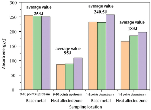
The Charpy absorbed energy value of X80 pipe are shown in . The allowable Charpy absorbed energy value in the criterion is 200J for minimum average and 150J for minimum single value in terms of base material, and 80 J for minimum average and 60 J for minimum single value for weld metal/heat affected zone (HAZ). Comparing the test results with criterion, all samples meet the standard requirements.
Figure 3. Impact mechanical properties.
The Charpy absorbed energy value of fillet weld are listed in . The allowable Charpy absorbed energy value in the criterion is the same as its for weld metal/HAZ of X80 pipe. All the results presented in table below meet the criterion.
Table 3. Charpy impact test results of fillet welds.
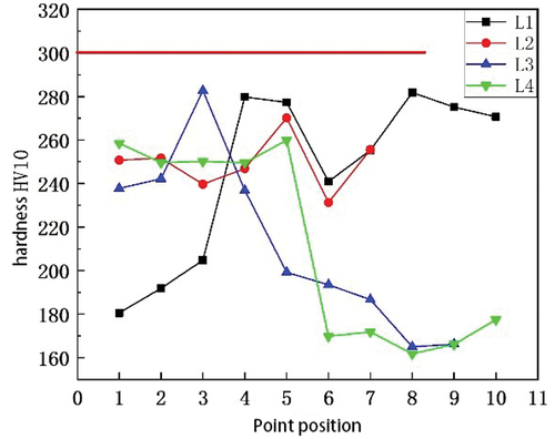
The Vickers hardness of fillet weld along the path shown in is drawn in . It is obvious that the hardness of all tested points are lower than 300 HV10, which also meets the criterion.
Figure 4. Vickers hardness of fillet weld.
In addition, chemical composition, bending properties and other mechanical properties of pipe and fillet weld required in specification were tested and contrasted to the criterion, all the physical-chemical properties meet the standard requirements.
Welding pass inspection
The cross section of fillet weld after grinding, polishing and eroding is shown in . The welding sequence and the number of welding pass required in the specification is shown in , from which the total number of welding pass could be inferred as 55 approximately if each welding bead thickness is 2.0 mm ~3.0 mm based on specification. According to , the actual welding pass is 17 in total, which is obviously much lower than the criterion.
Figure 5. Cross section of fillet weld.
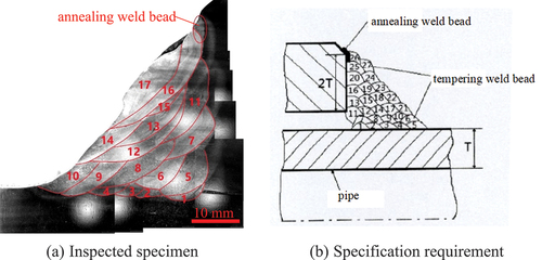
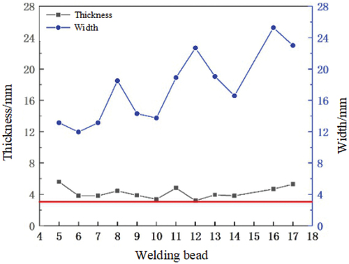
The thickness and width of each welding bead were measured under OM and presented in . The thickness of every welding bead is higher than 3.0 mm required in specification. Additionally, the width of last two welding beads exceeds 20 mm, which is accompanied by severe excessive heat input. In general, residual stress of the annular and thick wall fillet welds is relatively high due to high degree of constraint. The excessive heat input will further increase residual stress, which may lead to cracks [Citation26–30].
Figure 6. Thickness and width of weld bead.
Microstructure analysis
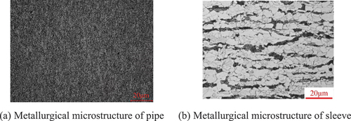
As shown in , the microstructure of the pipe is mainly composed of fine acicular ferrite (AF) and small amount of granular bainite (GB), while the sleeve is composed by AF and pearlite, distributed along the rolling direction. No abnormality is observed in material organization.
Figure 7. Metallurgical microstructure of pipe and sleeve.
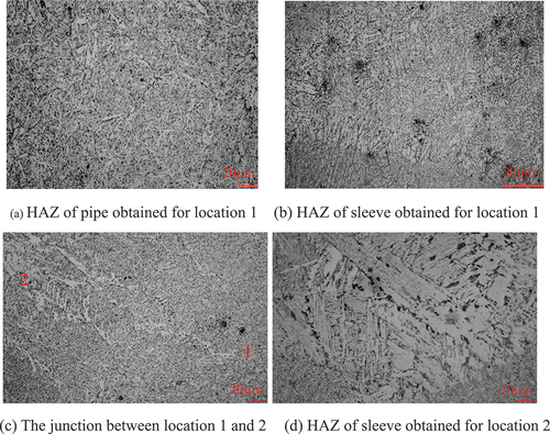
The fillet weld microstructure pointed in was observed under OM and shown in . In , the HAZ of location 1 is mainly composed of lath bainite (LB). There are no abnormal coarse grains which indicated the relatively low heat input of root welding. The weld structure of location 1 mainly contains AF, however, more proeutectoid ferrite appeared in location 2. Meanwhile, the microstructure of sleeve closed to location 2 is upper bainite and massive M-A constituent which have coarse grains as shown in . It represents that the heat input at location 2 increased significantly, and there is a significant difference in heat input between two locations.
Figure 8. Metallurgical microstructure of fillet weld.
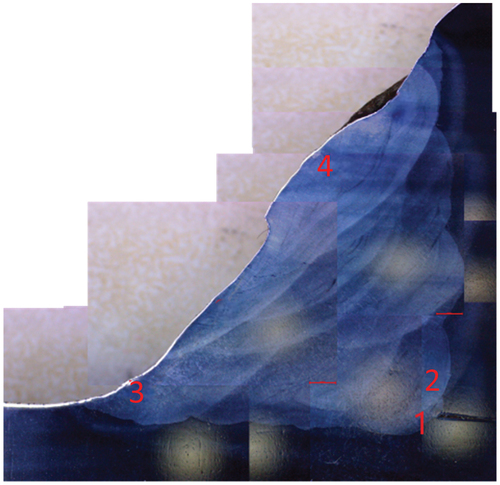
Figure 9. Metallographic morphology of location 1 and location 2.
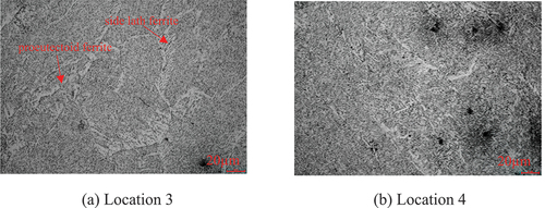
The columnar grains of location 3 and 4 shown in are relatively coarse, the width is approximately 70 ~ 100 μm. The columnar grains mainly consist of AF, with proeutectoid ferrite and ferrite side plate appearing at the boundary of columnar grains. It indicates relatively high heat input of location 3 and 4, which conforms to excessive width and thickness of the welding bead. Although the heat input is quite high, fine AF appeared in grains because of the wide welding pool at location 3, 4 and relatively fast cooling rate. The excessive heat input and fast cooling rate will increase residual stress, which together with coarse columnar grains, proeutectoid ferrite and ferrite side plate will induce the generation of cold cracking.
Figure 10. Metallographic morphology of location 3 and location 4.
Crack analysis
Three transverse cracks were detected on the fillet weld, and one typical crack was tested and analysed.
Macrostructure analysis
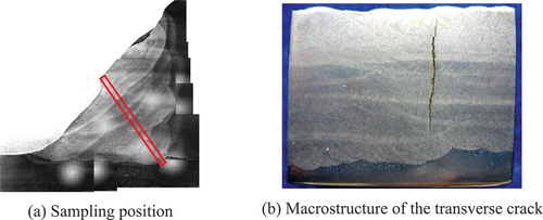
The sampling position and macrostructure of crack sample is shown in . In , it is obvious that the crack has the maximum width in the middle section of the weld, which indicates that the crack generated from filling beads and propagated in two opposite directions, respectively to the outer surface of the crack and to the HAZ.
Figure 11. Sampling position and macrostructure of the transverse crack.
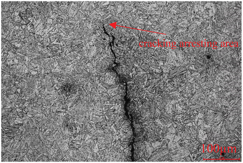
Crack propagation path is shown in . The crack initiated from the inside of weld seam and propagated from the weld to outer surface and HAZ of pipe. Eventually the crack terminated in HAZ (). The crack generally propagated in transgranular mode, which conforms to the basic characteristics of cold cracks.
Figure 12. Propagation morphology of transverse cracks.
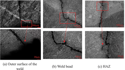
Figure 13. Crack terminates in the HAZ.
EBSD analysis
The transverse crack was conducted EBSD analysis, and the results is presented in . It is obvious in that columnar grains mainly consist of fine, uniform and cross-distributed AF, moreover, some proeutectoid ferrite is observed at the boundary of columnar grains. The crack propagated in transgranular mode and the direction of crack propagation deviated within certain grains, which is related to the specific crystallographic orientation of grains.
Figure 14. EBSD characterization results of crack.
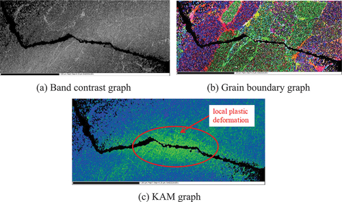
In Kernel average misorientation (KAM) graph, the colour at the edge and turning point of the crack marked by red ellipse presented distinct yellow-green colour, indicating local plastic deformation occurred at these locations before cracking. Dimple morphology resulted from plastic deformation can also be found at the location with larger local plastic deformation.
Crack fracture analysis
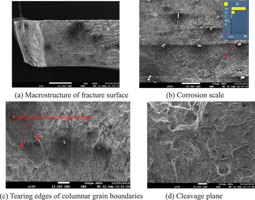
The crack sample was crushed by three-point bending and observed through SEM. The morphology of fracture under SEM before pickling is shown in . As is shown in , the fracture surface is flat without too much plastic deformation, and the fracture surface is covered with a thin layer of corrosion scales. The specimen was tested through EDS and the results in show that the main corrosion product was Fe-O, which is the iron oxide formed by corrosion and oxidation on the fracture surface after cracking. In , there are large cleavage facets and tearing edges of columnar grain boundaries on the fracture surface. The fracture mechanism is brittle fracture dominated by transgranular cleavage [Citation31].
Figure 15. The morphology of fracture surface before pickling.
After pickling, the fracture surface under SEM is presented in . Many small and shallow dimples appear on the large fracture surface after removing corrosion products, which results from local plastic deformation as illustrated previously. This local plastic deformation may be related to the fine AF structure and hydrogen enrichment in the weld [Citation32–34]. There are studies shown that under stress condition, especially under three-dimensional stress condition, local hydrogen enrichment can promote local dislocation slip and therefore cause local plastic deformation in these areas, which tends to form dimple fractures. Although there are dimples locally, it rarely contributes to macroscopic plasticity because all dimples are small and shallow. Therefore from a macro perspective, the fracture is still in brittle mode. In this case, the foggy weather during the type-B sleeve welding brought high humidity on the site, which may lead to excessive hydrogen in the weld and result in the generation of welding delay cracks. To confirm this inference, a small piece of fillet weld sample was cut and conducted diffusion hydrogen test. Unfortunately the captured hydrogen content is too low, which could not reverse the inference due to the long transport time before testing.
Figure 16. The morphology of fracture surface after pickling.
The crack propagated in a straight path. The fracture surface is relatively flat at lower magnification. There are cleavage facets whose size is consistent with the size of the columnar grains. It was observed at higher magnification that there were many small and shallow dimples on the surface of the cleavage facets which may be related to higher three-dimensional stress, hydrogen enrichment and fine AF structure in the fillet weld. The fracture mechanism is brittle transgranular cleavage, which can be determined as delayed crack considering the foggy weather at the construction site.
Residual stress analysis
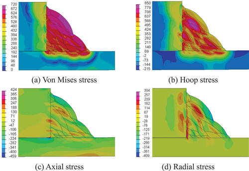
The results of numerical simulation are shown in . It is obvious in that the tensile stress of weld is high, especially the filling surface after 13 welding beads. The hoop stress and axial stress are shown in respectively. The hoop stress of weld is obviously much higher than the axial stress, which explains the generation of transverse cracks in weld resulting from the higher hoop stress. Meanwhile, stress concentration could be found at 13th and 14th welding beads, which illustrates the crack initiation in the middle of weld.
Figure 17. Residual stress nephogram after welding.
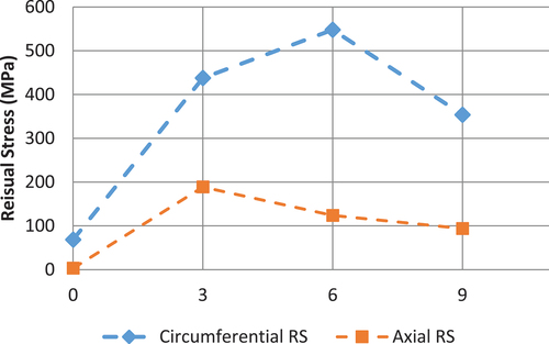
The residual stress acquired through experiment is presented in , with horizontal axis representing the clock position of fillet weld. The results show that the hoop residual stress at bottom is the highest, which is approximately 600MPa even after stress releasing.
Figure 18. Residual stress test results of fillet weld.
Comprehensive analysis
The type-B sleeve was not observed cracks through non-destructive testing until 2 days after welding, which infers that the crack is a cold crack. Nevertheless, chemical composition and mechanical properties of the fillet weld, pipe material and sleeve satisfy the requirement of standard. Therefore the cause of failure may occur in the construction process.
According to welding pass inspection, the sleeve with a thickness of 40 mm was filled with only 17 passes, while the welding passes estimated based on specification is approximately 55. The actual number of welding passes is missing nearly 70%, which leads to excessive thickness and width. In particular, the width of filling weld beads and top weld beads exceed the standard dramatically, which indicates excessive heat input. Additionally, the flat weld seams have wide bath and fast cooling rate. Those two factors result in relatively high residual stress.
The microstructure analysis shows that the columnar grains of fillet weld is relatively coarse due to high heat input of top weld beads. The width of the columnar grain is 70 ~ 100 μm, and it is mainly composed of AF, however, proeutectoid ferrite and side lath ferrite appeared at the boundary of columnar grains. The coarse columnar grains, especially the existence of proeutectoid ferrite and lath ferrite, will lead to a significant reduction in toughness and plasticity [Citation35]. On the other hands, finer AF is still formed under high heat input, which also reflects that the cooling rate is fast. The humidity during construction was quite high because of foggy weather. Therefore, the large hoop residual stress, combined with coarse grains and grain boundary defects, led to cracking. This is the crack source for delayed cracks.
The analysis of crack propagation and fracture surface shows that the crack propagated straightly and the fracture surface is flat. Meanwhile, there are large cleavage facets and tearing edges of columnar grain boundaries. The fracture mechanism is brittle fracture dominated by transgranular cleavage.
The residual stress analysis shows that the fillet weld is in high Von Mises stress level due to high heat input. There is obvious stress concentration in 13th and 14th filling weld beads through hoop residual stress results, which provides mechanical conditions for the generation of cracks. The hoop stress of fillet weld is significantly higher than the axial stress, which results in the cracks in transverse direction.
In summary, the reason of fillet weld cracking is that the welding process was not carried out in accordance with specifications, resulting in insufficient welding passes. Particularly the heat input of filling weld beads and top weld beads is too high, resulting in coarse grains and much proeutectoid ferrite and side lath ferrite. In addition the residual stress is extremely high due to high heat input and fast cooling rate, meanwhile, the hydrogen content in weld may exceed the standard because of the foggy weather during construction. All of the above factors contribute to the generation of transverse delayed cracks in the fillet weld.
Conclusions
The type-B sleeve with transverse cracking was conducted chemical composition analysis, welding pass inspection, energy spectrum analysis, OM, SEM and EBSD, as well as finite element simulation of residual stress to analyse the reason of weld cracking. The following conclusions could be obtained:
Insufficient welding passes led to excessive width and thickness, accompanied by coarse columnar in top filling beads, which aggravated the reduction of plasticity and toughness.
Excessive heat input and high residual stress provide stress conditions for crack generation and propagation.
The high humidity during construction leads to the enrichment of hydrogen in fillet weld, which induced delayed cracks.
The microstructure deterioration, high residual stress and hydrogen enrichment, together resulting in hydrogen-induced delayed crack, which is quasi-cleavage brittle fracture.
In future construction, it should pay attention to the humidity environment to prevent hydrogen enrichment. Moreover, welding should be carried out in strict accordance with the specification to prevent deterioration of microstructure and malicious increase of residual stress.
Acknowledgments
The authors wish to acknowledge the financial support from the project of “Research on failure mechanism for girth weld of high steel pipeline” (NO.WZXGL202105).
Disclosure statement
No potential conflict of interest was reported by the author(s).
References
- Guo L, Su X, Dai L, et al. Strain ageing embrittlement behaviour of X80 self-shielded flux-cored girth weld metal. Mater Technol. 2023;38(1). doi: 10.1080/10667857.2023.2164978
- Xu CM, Luo LH, Zhou HP, et al. Influence of B-type sleeve welding on the performance of X80 pipeline steel. Mater Protect. 2019;52(6):149–12.
- Zhang L, Wang ZZ, Jia XM, et al. Oil and gas pipeline defect repair method and field application. China Petrol Chem Stand Qual. 2019;39(20):2.
- Guo JY, Hu J, Li QD, et al. Research progress on corrosion and protection of oil and gas pipelines at home and abroad. Mater Protect. 2017;50(6):83–87.
- Li YG, Du J, Zhao GX, et al. Overview of long distance oil/gas pipeline defects and repair technology. Petrol Eng Constr. 2016;42(1):10–13.
- Li YG, Zhang W, Zhao Z, et al. Discussion on repair technology of girth weld defects of high-grade steel pipelines. Oil & Gas Storage Transp. 2020;39(3):7.
- Sun BL, Wang ZF, Song HB. Operation quality control of B-type sleeve used for hidden dangers treatment of circumferential welds in large-diameter and high-grade steel pipelines. Prot Oil & Gas Pipelines. 2019;5:48.
- Weaver MR, Maldonado AJ, Banuelos JL, Misra RDK. On precipitation hardening behaviour in a triaxial forged Mg-2Zn-2Gd alloy and relationship to mechanical properties. Mater Technol. 2023;38(1). doi: 10.1080/10667857.2023.2215038
- Yang C, Xu H, Wang Y, et al. Hot tearing analysis and process optimisation of the fire face of Al-Cu alloy cylinder head based on MAGMA numerical simulation. Mater Technol. 2023;38(1). doi: 10.1080/10667857.2023.2165245
- Misra RDK. Enabling manufacturing of multi-axial forging-induced ultrafine-grained strong and ductile magnesium alloys: a perspective of process-structure-property paradigm. Mater Technol. 2023;38(1). doi: 10.1080/10667857.2023.2189769
- Wang L, Li J, Liu ZQ, et al. Towards strength-ductility synergy in nanosheets strengthened titanium matrix composites through laser power bed fusion of MXene/Ti composite powder. Mater Technol. 2023;38(1). doi: 10.1080/10667857.2023.2181680
- Misra RDK, Challa VSA, Injeti VSY. Phase reversion-induced nanostructured austenitic alloys: an overview. Mater Technol. 2022;37(7):437–449. doi:10.1080/10667857.2022.2065621
- Misra RDK. On the relationship between the grain boundary bio-physical attributes with the cells in the physiological environment. Materials Letters. 2023;31:133443. doi: 10.1016/j.matlet.2022.133443
- Niu G, Zurob HS, Misra RDK, et al. Superior fracture toughness in a high-strength austenitic steel with heterogeneous lamellar microstructure. Acta Materialia. 2022;226(226):226. doi: 10.1016/j.actamat.2022.117642
- Li Q, Zuo H, Feng J, et al. Strain rate and temperature sensitivity on the flow behaviour of a duplex stainless steel during hot deformation. Mater Technol. 2023;38(1). doi: 10.1080/10667857.2023.2166216
- Ning H, Li X, Meng L, et al. Effect of Ni and Mo on microstructure and mechanical properties of grey cast iron. Mater Technol. 2023;38(1). doi: 10.1080/10667857.2023.2172991
- Misra RDK. Understanding the weakening of texture in multiaxial forged ultrafine-grained strong and ductile Mg-2Zn-2Gd alloy. Mater Technol. 2024;39(1). doi: 10.1080/10667857.2024.2321411
- Wu D, Liu ZJ, Su YH, et al. Effect of inclusions on microstructure of high strength steel weld metal and formation of cold crack. Hot Working Technol. 2018;47(23):4.
- Wen QP. Effect of weld microstructure on cold crack. Hot Working Technol. 2014;43(13):3.
- Fang CC. Analysis of embrittlement and cold cracking in the heat affected zone of low alloy-high strength steel welds. Welded Pipe Tube. 2001;24(3):3.
- Guo SL, Wu XL, Li E, et al. Influence of interpass temperature on the HAZ cold crack and microstructure thick wall 16MND5 steel structure. Electr Weld Mach. 2019;49(4):7.
- Arzola N, Araque O. Prediction of fatigue life for a transverse fillet welded joint and analysis of the influence of crack eccentricity on the failure. Dyna. 2013;80(182):95–104.
- Abe T, Arakawa J, Akebono H. Analysis of fatigue crack propagation behavior of structures with one-sided welding in fillet welded joint for load-carrying type. Mater Trans. 2022;63(7):1037–1045. doi: 10.2320/matertrans.MT-Z2022003
- Redza MR, Manurung YHP, Lidam RNA, et al. Transversed residual stress analysis on multipassed fillet weld 2D-using FEM and experiment. Adv Mater Res. 2012;576:181–184. doi: 10.4028/www.scientific.net/AMR.576.181
- Yukio U, Keiji F, Keiji N. Study on type of cracking of fillet weld based on residual stresses calculated by F.E.M. J Jap Weld Soc. 1975;44(3):250–257. doi: 10.2207/qjjws1943.44.6_466
- Nagai T, Kasai R, Suzuki R, et al. An estimation of factors influencing residual stress characteristics of fillet welded lap joints. Weld Int. 2017;31(12):202–210. doi: 10.1080/09507116.2016.1223239
- Hou GQ, Ma R, Qin J, et al. Effect of welding process parameters on residual stress of fillet weld. Welding Technol. 2016;45(3):37–39.
- Liu CX, Niu K, Fan ZD, et al. Study on cracking causes of 12Cr1MoV water wall of a supercritical boiler after repair welding. Hot Working Technol. 2022;51(3):157–161.
- Chen H, Gong JM, Tu SD. Simulation analysis of welding residual stress of typical closed girth weld multi-pass welding. Trans China Weld Inst. 2006;27(10):77–80+120–121.
- Gu SJ, Zhang YY, Yang P, et al. Numerical simulation on welding residual stress of tube and tube-tube sheet welded joints of exchanger. Hot Working Technol. 2010;39(3):155–157.
- Zhong QP, Zhao ZH. Fractography[m]. Beijing, China: Higher Education Press; 2006.
- Li HL, Yu ZZ, Li Y, et al. Relationship between hydrogen-induced additive stress and threshold cracking stress for a high-strength steel. Corros Protect. 2009;30(10):678–683.
- Song J, Curtin WA. Mechanisms of hydrogen-enhanced localized plasticity: an atomistic study using α-Fe as a model system. Acta Mater. 2014;68:61–69. doi: 10.1016/j.actamat.2014.01.008
- Ohaeri E, Eduok U, Szpunar J. Hydrogen related degradation in pipeline steel: a review. Int J Hydrogen Energy. 2018;43(31):14584–14617. doi: 10.1016/j.ijhydene.2018.06.064
- Wu YL, Jiao H, Yi R, et al. The effect of heat input on the microstructure and properties of high-strength weathering resistant steel FCAW joints. Weld Joining. 2019;548(2):65–70+74.