
 ?Mathematical formulae have been encoded as MathML and are displayed in this HTML version using MathJax in order to improve their display. Uncheck the box to turn MathJax off. This feature requires Javascript. Click on a formula to zoom.
Abstract
Titanium-based fiber metal laminates, also known as hybrid titanium composite laminates (HTCL), are new-age potential materials used in the field of supersonic and high-speed passenger aircraft due to their better corrosion resistance, higher stiffness, fatigue and impact resistance at both elevated and room temperature. However, the difficult-to-machine nature mandates using effective but sustainable coolant during machining. Therefore, in the present study, drilling of HTCL is done in a dry and cryogenic LCO2 environment, considering various responses such as thrust force, torque, surface roughness, tool wear, chip analysis, power consumption and specific cutting energy. Further, a life-cycle analysis was carried out to evaluate the impacts of these two cutting conditions. The results indicate that cryogenic cooling improved the hole surface finish (up to 25%) by reducing the torque values significantly by 25–30%. Furthermore, tool life is improved (up to 48.6%), and power consumption is reduced (up to 13.3%). These outcomes make cryogenic with LCO2 more favorable to use over dry conditions for this novel material. Nevertheless, condensing CO2 into liquid form necessitates a higher consumption of energy and natural resources. Furthermore, its direct release into the environment results in environmental impacts (up to 17–20%) compared to dry machining.
Introduction
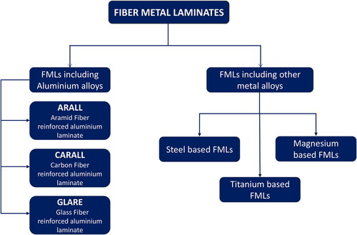
The requirements for lightweight and high-strength materials have led to the development of materials such as stacked composites and fiber metal laminates (FMLs). These materials help overcome the limitations of monolithic metals and fiber-reinforced composites, making them extremely useful in the aerospace and defence industries (Pawar et al., Citation2015). FMLs are developed by stacking metal alloy sheets (aluminum, titanium and magnesium) alternating with thin layers of fiber-polymer composites (glass or carbon fibers), whereas hybrid composite stack includes Ti/CFRP and Al/CFRP or stacked with reverse sequence of the constituents (Bolar et al., Citation2022). Sinmazçelik et al. (Citation2011) classified the FMLs based on metal plies as shown in , where three popular FMLs based on the aluminum alloy as a metal constituent and aramid fibers, carbon fibers and glass fibers as the fiber reinforced polymer (FRP) part are ARALL, CARALL and GLARE. Additionally, titanium, steel and magnesium-based FMLs have also been reported (Sinmazçelik et al., Citation2011). FMLs have a near-net shape; however, post-processing operations, including conventional drilling, are needed to assemble large structures (Pawar et al., Citation2015). Hole processing becomes a challenging task when many holes are required. However, 60% of rejections occur due to poor hole quality and defects like delamination and hole finish produced during the post-processing stage (Pawar et al., Citation2015). Therefore, several researchers have explored the machinability of FMLs, considering the drilling operation.
Figure 1. Classification of Fiber metal laminates based on metal alloys (Sinmazçelik et al., Citation2011). (adapted and modified).
Sridhar et al. (Citation2022) investigated the impacts of axial feed and spindle speed while drilling CARALL FML. The performance was evaluated considering the burr size, hole size, thrust force and surface roughness. A vital reduction in thrust force and burr size was observed when a higher spindle speed of 4000 rpm and a lower axial feed of 0.1 mm/rev were employed. At the same time, surface finish was enhanced with higher feed selection. Bolar et al. (Citation2022) conducted comparison studies evaluating the drilling and helical milling operations, considering various outputs, including surface roughness, machining forces, hole size, chip morphology and machining temperature. Lower cutting forces, machining temperatures with improved surface finish, and better tolerances were observed when the helical milling process was utilized. Ekici et al. (Citation2021) examined the hole quality while drilling CARALL using coated and uncoated tools, and they found that at higher feeds, hole diameters were accurate, while circularity error increased with increasing cutting speed.
Xu and El Mansori (Citation2016) explored the influence different cutting tool geometries and cutting sequences have on cutting forces, chip analysis, surface roughness, delamination factor and burr width while drilling bi-material stacked composite CFRP/Ti of 8 mm thickness. Experiments were performed using uncoated and PVD TiAlN-coated drills. An uncoated drill performed better than a coated drill for the same cutting condition. Also, good machined hole quality was observed when drilling Ti to CFRP drilling sequence. However, the CFRP-to-Ti drilling sequence showed a lower delamination tendency than the Ti-to-CFRP drilling sequence. Wang et al. (Citation2020) studied the wear occurring at the main and chisel cutting edge of carbide step drills when drilling Ti/CFRP stacks. Adhesion and abrasion were determined as principal wear mechanisms. Kumar et al. (Citation2020) compared the machinability of Ti/CFRP/Ti stack laminates during dry and cryogenic mechanical drilling using P-tipped solid carbide drills. The process was evaluated considering surface roughness, burr height, thrust force, torque and hole size. An improvement in hole quality was noted under cryogenic machining conditions. Also, compared to dry drilling, thrust force increased during cryogenic machining. Rodriguez et al. (Citation2023) explored the use of sustainable liquid carbon dioxide (LCO2) coolant for drilling CFRP, Ti-6Al-4V and CFRP/Ti-6Al-4V using different tool geometries. A significant improvement in surface integrity and burr height reduction was noted during cryogenic machining as opposed to dry conditions. Shyha et al. (Citation2011) investigated the hole quality while drilling Ti/CFRP/Al stacks using coated and uncoated drill bits in flood cooling and spray mist environments. Reduction in burr height was observed when the Ti/CFRP/Al stacking sequence was used. In contrast, lower delamination was observed in the composites with Al/CFRP/Ti as a stacking sequence. Impero et al. (Citation2018) equated the wet and cryogenic (LN2) deep hole drilling operation on CFRP/Ti stacks using uncoated tungsten carbide (WC) drill bit and incessantly measured both thrust and torque. Cryogenic machining was preferable to wet machining as it significantly reduced torque and thrust force.
Qiu et al. (Citation2021) deliberated on using different drill geometries for drilling CFRP/Ti stacks. Experiments were carried out with LN2 as a cutting fluid. Accordingly, the use of a candle stick drill lowered the interfacial damage. An et al. (Citation2020) explored the influence of the CFRP/Ti stacking sequence on cutting temperature and thrust force. Higher force and temperature were recorded while machining composites with CFRP/Ti as a stacking sequence. However, thrust force and temperature reduced considerably when machining a composite with a Ti/CFRP stacking sequence. Wang et al. (Citation2014) examined the wear performance of uncoated and coated WC drills for drilling titanium and CFRP/Ti stacks. A significant enhancement in tool life was noted when working with CFRP/Ti stacks compared to stand-alone titanium alloy. Khanna et al. (Citation2020) studied CFRP drilling under cryogenic and dry conditions and evaluated industry-relevant responses such as delamination factor, thrust force and hole quality. They found that surface roughness decreased considerably under cryogenic conditions. However, the delamination factor increased significantly with the cryogenic process. Ji et al. (Citation2020) studied the CFRP/Ti stack drilling operation, considering specific energy consumption using dry and MQL methods. Energy efficiency and hole quality improved when higher feed rates were employed with MQL conditions, while torque and specific cutting energy reduction were observed when vegetable-based cutting fluid was used. Rodriguez et al. (Citation2021) evaluated the CFRP/Ti stack drilling by considering burr height, power consumption, tool integrity and tool wear using a CVD-coated drill bit. The utilization of CO2 cryogenic cooling improved the performance compared to dry drilling, as no thermal damage was observed. Also, cryogenic coolant helped improve the tool's integrity. However, the cutting torque and power consumption increased with the employment of CO2 cryogenic coolant.
Khanna et al. (Citation2022) examined two cooling approaches, viz., dry and LCO2, for end milling of GFRP, considering tool wear, cutting force, temperature, surface roughness and power consumption. In addition to this, they also performed Life cycle analysis for both conditions and concluded that under responses, cryogenic with LCO2 condition dominated by exhibiting better performance over dry. On the other hand, dry cutting consumes less energy and natural resources, eventually reducing the impact on the life cycle. Other research work by Shah et al. (Citation2021a) explored the Ti-6Al-4V drilling operation using LCO2, and flood coolant. Reduction in tool wear and power consumption was reported with the cryogenic technique. They proposed LCO2 as a sustainable alternative with superior machining performance to conventional coolant like flood.
HTCL exhibits low machinability, and the challenge primarily arises from the differing properties of FRP and Ti alloys. FRP is an anisotropic material comprising two distinct components: reinforcing fibers and a polymer matrix. Conversely, Ti alloys exhibit poor thermal conductivity, a low elastic modulus and limited chemical affinity with most tool materials (Xu et al., Citation2016). The cutting tools are subjected to severe tool wear due to the abrasive nature of the reinforcement fibers and higher hardening rate exhibited by the Ti alloy. Moreover, the lengthy heated metallic chips can induce delamination, fiber pullout and burrs in the metal layers, presenting the entry and exit of the drilled holes. (Kim and Ramulu, Citation2004, Citation2007). Specifically, conventional drilling of HCTL has been seen to yield defects in the form of voids, poor surface quality on the interior surface of drilled holes, delamination of the face sheet material, and backside rupture of the titanium lower face sheet (Kim and Ramulu, Citation2004, Citation2007). Therefore, this combination creates hurdles while machining. However, combining both materials addresses their individual shortcomings, and the outcome is a lightweight, high-strength material with enhanced thermal, mechanical and tribological properties (Pawar et al., Citation2015).
As reported, various researchers have analyzed hole drilling in CFRP/Ti or Ti/CFRP stacks. Moreover, conventional drilling of Al-based FMLs like GLARE, CARALL and ARALL has been explored. Nevertheless, they present certain limitations concerning high operating temperatures and damage tolerance under severe environmental conditions (Li et al., Citation2017). Due to their low density, cost-effectiveness and superior corrosion resistance compared to aluminum alloys, magnesium alloys are increasingly utilized in manufacturing FMLs, particularly in the automobile sector (Alderliesten et al., Citation2008). However, the lower stiffness of magnesium alloys necessitates thicker sheets during fabrication, resulting in properties similar to those of aluminum alloys (Kazemi et al., Citation2020). Stainless steel alloys can mitigate the issues of galvanic corrosion observed in Al-based FMLs and possess better properties than Al; however, they have higher density compared to titanium alloys and lack the excellent corrosion resistance of Ti alloys (Kazemi et al., Citation2020). Ti alloys offer exceptional corrosive and mechanical properties, including superior stiffness, strength, fatigue resistance, impact performance, and suitability for high-temperature applications (Li et al., Citation2018). The elevated temperatures encountered in supersonic flight require the utilization of titanium instead of aluminum, as it can endure higher operating temperatures for prolonged durations (Johnson et al., Citation1998). From the literature, it was found that the research evaluating the life cycle analysis of HTCL and the environmental impacts involved in the fabrication and drilling of HTCL remains less explored. Moreover, scant studies are available that report the machinability of hybrid titanium composite laminates (HTCL). These reasons make Ti-based FMLs (HTCL) potentially worthwhile material for exploring its machinability and sustainability aspects. Therefore, the present work investigates the mechanical drilling of HTCL under dry and LCO2 cryogenic machining for various machining responses, including surface roughness, torque, thrust force, tool wear and power consumption. In addition, the morphology of the generated chips is evaluated. The forthcoming section will provide details, including the materials and characterization methods. Subsequently, the drilling performance will be examined, followed by a Life Cycle Assessment to evaluate sustainability aspects. Finally, conclusions will be drawn based on the findings of the investigation, experimental setup and research methodology.
Fabrication of HTCL
The titanium (Ti-6Al-4V) sheets of 0.5-mm thickness were initially cut to the desired dimension (120 mm × 60 mm) using an abrasive water jet machining process. The titanium sheets were subjected to mechanical abrasion to improve the interfacial adhesion between the titanium and CFRP surfaces. Initially, titanium sheets were mechanically abraded using 120-grade sandpaper to create a rough pattern on the surface. After abrasion, the sheets were rinsed with distilled water and dried with hot air. The sheets were finally cleaned using acetone to obtain a dirt-free surface. A unidirectional carbon fiber prepreg with a thickness of 0.2 mm (Bhor Chemicals & Plastics Pvt. Ltd.) was used for the carbon fiber reinforcement. The prepreg was manufactured using epoxy resin (A-45), having a resin content of 38 ± 3% and a fiber density of 200 GSM. The prepreg sheets were cut according to the desired orientation, and the dimensions were the same as the titanium sheet. The vacuum bagging method was used to cure the specimens in an autoclave.
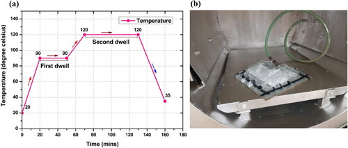
shows the schematic representation of specimen preparation using the vacuum bagging method. The mold plate was initially applied with a release agent for easy post-curing removal. The alternate layers of titanium sheets and carbon fiber prepreg were stacked as per , with fibers oriented along the rolling direction of titanium alloy. The stacked specimen was placed on the mold plate. The peel ply is placed above the stacked laminate to remove the cured specimens easily. Breather cloth with the required measurement was cut and placed above the peel ply to facilitate the vacuum action on the specimens in an autoclave. The vacuum bagging method was carried out with the help of sealant tape over the mold plate. The whole was placed inside the autoclave for curing. The curing cycle recommended by the prepreg manufacturer was adopted to cure the specimens in the autoclave. The specimens were cured at a pressure of 4 bar for 3 h as per the cure cycle depicted in . Finally, the specimens were taken out of the autoclave, resulting in a thickness of 5.34 mm. illustrates the fabricated HTCL specimen.
Figure 2. (a) schematic representation of specimen preparation using vacuum bagging method and (b) schematic of an alternate layer of Ti sheets and carbon fiber prepregs.
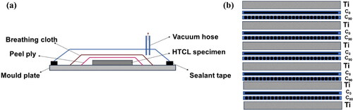
Figure 3. (a) curing cycle of the HTCL specimen and (b) Fabricated HTCL specimen.
Drilling experiments
reveals the setup used to execute the drilling experiments. The workpiece was clamped atop the Kistler dynamometer, which was employed to measure the drilling forces and torque. Experiments were conducted under cryogenic LCO2 () and dry machining conditions (). details the cutting tool and cutting variables considered for performing the drilling operation. The machining trials were carried out on the HTCL work material. The drilling operation was conducted using a PVD-coated TiAlN tungsten carbide (WC) drill of 6-mm diameter with a 140° point angle and 30° helix angle.
Figure 4. Image of experimental setup indicating two machining conditions: (a) Cryogenic machining and (b) Dry machining and instruments for various response measurements.
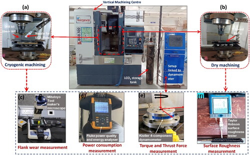
Table 1. Details about machine tool and cutting tool.
Response measuring instruments
The hole-making operation was evaluated using various response measurements, including thrust force (Fz), torque (T), surface roughness (Ra), tool life (flank wear), power consumption (W) and specific cutting energy (SCE) in J/mm3.
The tool flank wear measurement under dry and cryogenic LCO2 machining conditions was conducted using a Tool maker’s microscope made by Mitutoyo (). The microscope is coupled with a QM-Data200 unit to measure flank wear. Five readings were made at each measurement stage, and the average was taken for both dry and cryogenic machining. Power consumption and SCE (J/mm3) were measured using a Fluke three-phase power quality analyzer (Model: 435 and Series: II), as shown in . A Kistler-made 4-component tool dynamometer of type 9272, as shown in measured the cutting forces. The dynamometer has a measurement range of −5 kW to +5 kW and is attached to a charge amplifier (Kistler 5070 A) and analog-to-digital converter (type 5697 A). It has a sensitivity of 7.6 pC/N in the X and Y direction and −3.6 pC/N in the Z direction. The force data was acquired using Dynoware (type 2825 A) software, with the sampling rate set at 1000 Hz. Surface roughness values, mainly arithmetic mean surface roughness (Ra), were measured by a portable Taylor Hobson Talysurf Surtronic S-128 surface roughness tester, incorporating a diamond stylus of 5 μm tip radii (). During surface roughness measurement, sampling and cutoff lengths were set at 0.25 and 2.5 mm, respectively.
Results, analysis, and discussion
Thrust force and torque
Thrust force is a factor that affects the material’s machinability and hole quality (Kumar et al., Citation2020). A significantly higher force can induce vibration and deteriorate the hole quality (Bolar et al., Citation2022). depicts a typical thrust variation observed while drilling Ti-based fiber metal laminate (HTCL). Initially, the absence of contact between the drill and laminate results in near-zero thrust forces, but as the drill progresses and comes into contact with the laminate, a rise in thrust force is observed. The apparent peaks and valleys are due to the disparate material properties of fiber and metal laminates. Observations are in line with those reported when drilling CARALL and GLARE FMLs (Sinmazçelik et al., Citation2011; Ekici et al., Citation2021; Sridhar et al., Citation2022). Higher thrust force magnitude was observed in the titanium layer (peaks a–f) due to its elastoplastic deformation, leading to spiral chips and higher mechanical resistance (Kumar et al., Citation2020). Meantime, lower thrust force magnitude when cutting carbon fiber layers (valleys a’–e’) is attributed to its brittle fracture and the nature of powdery chips (Kumar et al., Citation2020). Furthermore, as the drill bit gradually progressed toward the hole exit, a drop in the force magnitude was noted, resulting from the lower resistance offered by the last metal sheet (peak f). Eventually, as the drill bit exits the last layer, the thrust force declines rapidly and approaches zero (Giasin et al., Citation2015).
Figure 5. Thrust force profile during drilling of HTCL in (a) dry, (b) cryogenic conditions.
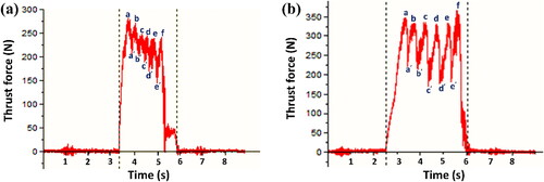
As indicated in , cryogenic drilling increased the thrust force magnitude when compared with dry drilling operations. The average thrust force in dry conditions is approximately 12–17% less when compared with thrust forces in cryogenic conditions. Typically, when subjected to cryogenic temperatures, there’s a notable rise in the modulus of elasticity, strength and hardness (Shokrani et al., Citation2013). Ahmed et al. (Citation2016) observed that when drilling titanium alloys, there was an upsurge in thrust force at extremely low temperatures. The increased thrust force in cryogenic conditions is attributed to the low temperature of the coolant, which increases the hardness of the material (Kumar et al., Citation2020). In contrast, the opposite pattern emerged for torque, indicating a decline in its magnitude in cryogenic conditions, as shown in . Dry conditions have, on average, 25–30% higher torque values than cryogenic conditions. This can be attributed to the significant influence of friction between the tool and chip interfaces and the entanglement of long, hot chips around the drill bit on torque generation, which diminishes with the application of cryogenic cooling. The utilization of liquid carbon dioxide (LCO2) results in the formation of a lubricating film at the tool-workpiece interface, thereby reducing the coefficient of friction and minimizing tool-chip adhesion, ultimately leading to a decrease in torque magnitude. These results agree with those obtained when drilling Ti/CFRP/Ti stacks under dry and cryogenic conditions by Kumar et al. (Citation2020). The primary cause of the thrust force surge during cryogenic drilling is the elevated material hardness. The effects of broken segmented chips and smooth chip evacuation were mainly on the torque values, which were reduced during cryogenic drilling. Conversely, the principal factors contributing to the surge in torque readings in dry drilling are the heightened resistance arising from the absence of external lubrication and the entanglement of chips around the drill bit, as shown in , resulting in a significant increase in torque values. However, the impact of material hardness on torque values was found to be negligible. In another investigation Agrawal et al. (Citation2022) observed analogous effects and identified corresponding causes in their study.
Figure 6. (a) Torque and (b) thrust force variation under dry and cryogenic machining conditions.
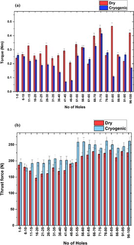
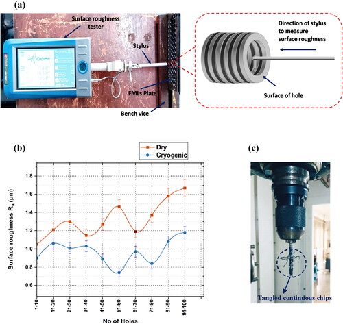
Figure 7. Surface roughness measurement for dry and cryogenic machining under same cutting parameters (a) surface roughness (μm) comparison for both machining conditions, (b) measurement of surface roughness of holes through surface roughness tester, and (c) tangled Ti chips around the drill bit during dry machining.
Surface roughness
Surface roughness is vital for determining hole quality, influencing friction, wear, corrosion resistance, etc (Pawar et al., Citation2015). It can significantly improve the functionality of the machined parts (Sridhar et al., Citation2022). displays the means and methods involved in measuring the surface roughness of holes drilled under dry and cryogenic machining conditions. The reported surface roughness values are an amalgamation of the roughness of titanium and carbon fiber layers. The recommended roughness values of CFRP/Ti stacks for their aerospace application are 3.2 μm for CFRP and 1.6 μm for Ti and Al alloys (Kumar et al., Citation2020). As indicated in , roughness values for drilling under dry and cryogenic machining for the same cutting parameters and same cutting tool are below 3.2 μm. However, on average, roughness values for dry drilling are 22–25% higher than those for cryogenic drilling. The higher roughness during dry drilling is mainly due to long continuous chips and built-up edges (BUEs) abrading the machined surface. On the other hand, cryogenic drilling enhanced the hole surface quality. The apparent reason behind this is the reduced temperature, which significantly reduces the chances of the BUEs and tangled chips forming. shows the tangled titanium chips around the drill bit during dry drilling, which is one of the major factors behind higher surface roughness under dry drilling. However, this problem was tackled by the embrittlement process at low temperatures in cryogenic drilling. clearly illustrates that dry drilling exhibits a higher variation in Ra (average mean surface roughness) compared to cryogenic drilling. This discrepancy can be attributed to the presence of more uncut fibers within the hole depth during dry drilling. Since surface roughness is directly measured on this continuously stacked composite, the interference of these uncut fibers with the stylus during measurement can result in sudden fluctuations in the values. Conversely, in cryogenic drilling, the presence of fewer uncut fibers, which is attributed to the brittle fracture due to the enhanced stiffness of CFRP at low temperatures (Kumar et al., Citation2020) can be the reason for lower fluctuation in surface roughness. Furthermore, no significant changes were observed based on the number of holes drilled; however, on average, dry drilling displayed higher surface roughness values compared to cryogenic drilling.
Tool wear
Tool wear is pivotal in determining the hole quality, power consumption and, ultimately, the machinability of any material (Xu et al., Citation2020). It is a significant factor in describing many attributes, such as manufacturing costs, environmental effects and tool efficiency (Wang et al., Citation2014). Drilling parameters, cooling and lubrication conditions and workpiece material mainly influence tool life for most of the materials (Wang et al., Citation2020). It is caused by many individuals and combinations of those individuals wearing mechanisms such as chipping, attrition, adhesion, abrasion, etc (Wang et al., Citation2020).
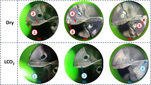
The progressive flank wear for drilling HTCL with CFRP as a fiber-reinforced epoxy constituent in cryogenic and dry machining conditions is shown in , respectively. The investigation showed an approximately 48.66% increment in tool life when drilling was performed in the cryogenic environment as compared to dry settings. The wear mechanism and their amalgamation, which led to the failure of the tool in both conditions, are displayed in . The main contributing wear mechanisms in dry settings are corner wear at one of the cutting edges, high chemical reactivity on both cutting edges by titanium due to its lower thermal conductivity, and high chemical affinity, which promotes adhesion on the drill bit. Abrasion wear is ascribed to the carbon particles in the carbon fiber layers, built-up edges in the absence of coolants and lubricants, and higher tool chip contact length during dry conditions. These are some of the significant factors that play a role in rapid tool wear during dry conditions from the initial stages when compared to cryogenic conditions, eventually leading to catastrophic failure at the 97th hole. On the other hand, cryogenic drilling exhibited a gradual and more uniform increase in tool wear as the drilling progressed. For most drilled holes between the 15th and 80th hole, tool wear remained reasonably constant in cryogenic conditions, unlike in dry conditions. In cryogenic conditions, heat dissipation from the cutting zone enhances tool life. The impact of hardened material on the increase in tool wear was minimal. Conversely, the decreased temperature during cryogenic drilling improved chip evacuation by facilitating smoother chip removal. Additionally, it reduced tool-chip contact due to the formation of short, brittle chips, thereby reducing built-up edge (BUE) formation. These combined effects resulted in an increased tool life compared to dry drilling. The wear occurred mainly due to abrasion wear, corner wear of the cutting edges and significantly less chemical reactivity on the cutting edges than dry drilling. Rodríguez et al. (Citation2021) made similar observations and identified corresponding causes, noting that LCO2 enhanced tool integrity while reducing adhesion and the occurrence of burnt phenomena.
Figure 8. Flank wear progression for (a) cryogenic machining, (b) dry machining, and (c) Dry vs. Cryogenic comparison with respect to the number of holes drilled.
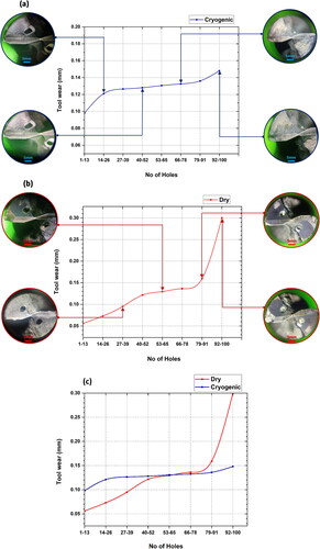
Figure 9. Flank wear images of drill bits for the dry and cryogenic environments, where (1) corner wear, (2) chemical reactivity due to Ti6Al4V on the tool, (3) BUE on the corner, (4) abrasion, and (5) catastrophic failure.
Chip analysis
Chip morphology during FMLs drilling is significant, as large-sized chips can abrade the machined surface and deteriorate the surface finish (Sridhar et al., Citation2022). Also, longer chips can entangle around the drill bit and increase friction and power consumption (Bolar et al., Citation2022). Moreover, with longer chips, the tool-workpiece contact area increases. This eventually creates an obstacle for heat transfer from the cutting zone and aids in adhesive wear when low-thermal conductivity materials like titanium and its alloys are machined (Ahmed et al., Citation2016). Therefore, the machining operation is expected to promote chip breakability. Only titanium chips are analyzed, considering the production of discontinuous powdery chips while drilling carbon fiber layers.
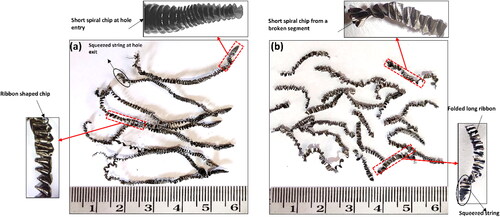
shows the macroscopic images of chips generated under dry and cryogenic conditions. As noticed, long combined spiral and ribbon-shaped chips are produced in dry conditions, whereas the short and broken segmented types of chips are produced in cryogenic settings. In dry conditions, spiral chips are generated at the hole entry. With an increase in hole depth, the cutting zone temperature increases, making it a ribbon-type shape, as shown in . This type of chips in dry drilling increases the surface roughness and tool wear compared to cryogenic drilling, as illustrated in Sections 3.2 and 3.3. Conversely, uniform and narrowly segmented chips produced during cryogenic machining with LCO2 presented lower friction and easier chip evacuation and ultimately produced smoother hole surfaces and low power consumption due to no entanglement around the drill bit, which eventually enhanced tool life. Similar observations were obtained by Qiu et al. (Citation2021).
Figure 10. Chips formed during drilling in (a) dry conditions and (b) cryogenic condition.
Power consumption analysis
Manufacturing process economics is significantly influenced by the power consumed during that process (Khanna et al., Citation2022). The machining process with tailored parameters and cutting conditions can consume less power, which is favorable for industries to achieve sustainable goals (Shah et al., Citation2021c).
The current study investigates the power consumed by machine tools during the drilling of HTCL using the cutting parameters under dry and cryogenic LCO2 machining conditions, as shown in . Further, specific cutting energy, which indicates the energy required to remove a unit volume of workpiece material during drilling, is also studied comparatively under both cutting environments, as illustrated in .
(1)
(1)
(2)
(2)
(3)
(3)
Figure 11. comparison of (a) power consumption and (b) specific cutting energy while drilling HTCL during dry and cryogenic environments.
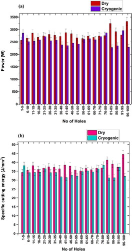
The average power consumption for each hole was calculated from data obtained through the power quality analyzer. In aggregate, around 13.37% lower power consumption and 10.26% lower SCE consumption were recorded for the same number of holes drilled using LCO2 when compared to dry conditions. The power consumed by the dry and cryogenic environments ranged between 2700–3000 W and 2400–2700 W, respectively. Reduced chip clogging tendency and friction developed at the tool-workpiece interface and effective cooling during a cryogenic environment aided in lowering the power consumption. In cryogenic machining, the power required to overcome the resistance offered by chips is reduced because of the formation of uniform and small-segmented chips. Also, torque measured during cryogenic conditions is lower than in dry drilling, and high torque values are attributed to consuming more power in general (Rodríguez et al., Citation2021). Similar observations were made by Khanna et al. (Citation2022) and Rodriguez et al. (Citation2023) during their study of comparison between dry and cryogenic cutting environments.
Life cycle assessment
The impacts of dry and cryogenic conditions on the environment are assessed using an Open Life cycle assessment (OpenLCA) platform. LCA is a scientific method that helps analyze a product or process’ impact on ecology throughout its life cycle. The assessment follows the procedure based on the ISO standards’ guidelines 14040 and 14044: 2006 for the investigation (Khanna et al., Citation2021).
The cradle-to-cradle principle focuses on recycling and reusing products within or outside their life cycle chain, while the cradle-to-grave process examines a product’s life cycle from raw material extraction to waste disposal. However, given the practicality and efficiency of using the gate-to-gate method for comparing the environmental impacts of various cutting fluids in machining, it is the chosen approach for this life cycle assessment. Accordingly, the LCA study is presented as goal and scope definition, life cycle inventory (LCI), life cycle impact assessment (LCIA) and result interpretation in the following subsections.
Goal and scope definition
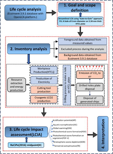
The investigation aims to assess the environmental performance of conventional drilling of HTCL – a titanium-based fiber metal laminates, under dry and cryogenic LCO2 machining conditions. Literature indicated the existence of studies on life cycle impact analysis of drilling of monolithic titanium and CFRP, although the ramifications on ecology and environment due to drilling of HTCL have not yet been explored. Therefore, the research aims to evaluate the impact of dry and cryogenic drilling operations on the environment using the “gate-to-gate” method, eradicating material mining, usage of the final product and disposal. In other words, this streamlined LCA simply evaluates environmental loads arising from energy consumption during the fabrication of HTCL and its machining process.
The functional unit (FU) is an apparent standard for comparing the alternative processes (machining environment used) in the streamlined LCA approach. In this investigation, a through-hole drilling of 6-mm diameter in a 5.34-mm thick HTCL plate is selected as a functional unit, and ReCiPe 2016 midpoint (H) is employed as the impact assessment tool. Here, 18 midpoint indicators were considered to categorize the results with higher accuracy. It also provides exhaustive information as compared to three endpoint indicators or a single overall score (Shah et al., Citation2021a).
During the analysis, the processes can be foreground or background. The foreground processes are those where primary data is gathered from job sites or experiments conducted, while in the background processes, data is obtained from life cycle inventory databases such as ecoinvent (Khanna et al., Citation2022). showcases the system boundaries and input-output flows of materials, considering dry and LCO2 cutting conditions. Foreground and background processes are shown in the colors, whereas the excluded processes in consideration of SLCA are shown in the grey color box.
Figure 12. An illustration showing the LCA steps and system boundaries with the processes involved.
The preliminary proposals and assumptions considered for overcoming the possible edges of LCA performed are mentioned below (Khanna et al., Citation2022):
Electricity usage was considered according to Gujarat, India, production mix.
The influence of leakage of cutting fluid is not considered.
Chip recycling and remelting are neglected.
The vertical machining center, air compressor and other apparatuses used during drilling are considered to have an insignificant impact.
Workpiece material transport and device depreciation are ignored, owing to their trivial impact.
Life cycle inventory analysis
The section defines the flow between the input and output components of the boundary system under consideration. The electricity and LCO2 consumption data are accumulated when drilling HTCL to produce a through hole of 6-mm diameter in a 5.34-mm thick plate. The values of inventory generated during drilling have been presented in . describes the database used in producing one drill bit unit, whereas showcases the databases used in fabricating HTCL specimens. depicts the Ecoinvent 3.9.1 database considered during the study.
Table 2. Details of Life cycle inventory.
Table 3. Database to produce 1 unit of solid carbide drill bit (Maheshwari et al., Citation2023).
Table 4. Database for production of one HTCL workpiece sample.
Table 5. Data sources for LCI.
Life cycle impact analysis
This facet of LCA showcases the association between the process under analysis and its possible impacts. Generally speaking, the assessment model for LCIA can be either a midpoint or endpoint, depending on the objectives and study scope as well as the information gathered from the inventory (Shah et al., Citation2021b). Among the many LCIA methods, such as CML 2002, Eco indicator 99, ReCiPe, TRACI, and ReCiPe 2016 are widely popular due to several advantages, such as comparatively fewer assumptions and fewer complications (Shah et al., Citation2021b). This promises more accurate and desirable results. In ReCiPe 2016 v1.03, midpoint (H) LCIA methodology was employed to ascertain their 18 impact categories using OpenLCA.
Life cycle result interpretation
Decoding the outcomes of LCA is vital for reducing the environmental impacts of cutting fluid techniques (Maheshwari et al., Citation2023). displays the absolute values of 18 impact categories based on the ReCiPe 2016 midpoint(H) for dry and cryogenic conditions.
Figure 13. Comparison of dry and cryogenic conditions based on their impacts on the environment.
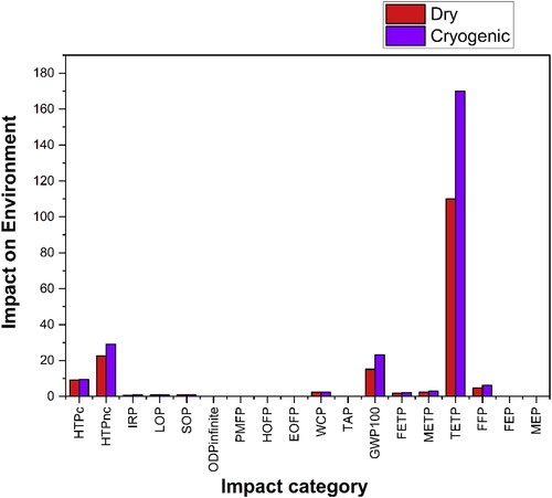
Since cutting fluid was excluded in dry drilling, environmental impacts that emerged due to cutting fluid are zero. However, higher machining temperatures generated during dry conditions resulted in deterioration of surface integrity and increased friction and resistance, which increased energy consumption. Additionally, high temperatures are not viable considering their adverse impact on tool life and productivity. Similar outcomes were observed when drilling GFRP under dry and cryogenic with LCO2 conditions (Khanna et al., Citation2022) and drilling VT-20, a titanium alloy, under dry, flood, and cryogenic conditions (Khanna et al., Citation2021).
It is evident that superior impact values have been found for LCO2, when compared to dry conditions, considering the impact of fluid and energy consumption. However, higher impact values have been observed for dry machining due to energy consumption as compared to LCO2 cutting conditions (Khanna et al., Citation2022). Therefore, it is realized that the contribution of environmental impacts is higher with the use of cryogenic cutting fluid in comparison with dry operation. The higher impacts originated in the TETP impact category, followed by HTPnc and GWP100. Cryogenic machining with LCO2 results in around 32–35% more impacts on ecology in the TETP impact category, whereas an average of 29.46% and 54.6% higher impacts were observed in the HTPnc and GWP100 categories.
exhibits the relative indicator results of respective project variants. For each indicator, the maximum result is set to 100%, and outcomes of other variants are indicated in relation to the maximum result. It is evident that cryogenic is, on average, 17.5–20% more impact generator during drilling than dry machining because of the LCO2 production and its direct emission in the machining environment. is the radar diagram showing the impacts generated by dry drilling in relation to cryogenic fluids by setting the impacts of a cryogenic fluid on a boundary level. shows the impact assessment results of various categories under dry and cryogenic machining.
Figure 14. Relative indicator results of the respective project variants for dry and cryogenic machining.
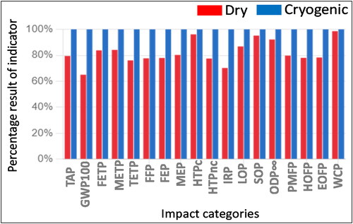
Figure 15. Radar diagram showing the impacts on the environment in various categories.
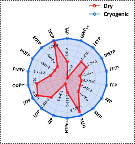
Table 6. Impact assessment results of various categories under both cutting conditions.
Consequently, LCO2 emerges as a “hotspot” in terms of generating environmental impact, in comparison to dry conditions, which is less impactful, considering the exclusion of cutting fluid during dry machining. While CO2 acquired is a byproduct of the chemical procedure, converting it into liquid form as LCO2 necessitates compressing gaseous CO2 to around 60 bars, resulting in increased electricity and natural resource consumption (Khanna et al., Citation2022). Consequently, the environmental impacts associated with LCO2 are greater when compared to dry machining.
Conclusions
In this work, conventional drilling of HTCL for the same cutting parameters and number of holes was done under dry and cryogenic machining environments. Various responses such as thrust force, torque, surface roughness (Ra), tool wear, chip analysis and power consumption were compared under the two machining settings. In addition, the ReCiPe 2016 midpoint (H) was applied to conduct LCA analysis. Based on the results and LCA, the following conclusive remarks are listed:
Dry conditions have, on average, 25–30% higher torque values when compared to the cryogenic state; however, average values of thrust force in dry conditions are approximately 12–17% less when compared with thrust forces in cryogenic conditions. Increased torque in dry conditions consumes more power, significantly impacting surface roughness and reducing tool life. However, higher thrust forces during cryogenic machining do not significantly affect tool wear and surface roughness.
The hole surface integrity improved under cryogenic machining due to reduced friction, easy chip evacuation, and lesser BUE formation. A substantial 22–25% reduction in surface roughness was achieved under cryogenic conditions as opposed to dry ones.
On the drill bit with a cryogenic environment, lower intensities and a combination of wear mechanisms such as abrasion, adhesion, chipping, corner wear and chemical affinity led to approximately 48.66% increment in tool life under cryogenic conditions, unlike dry conditions where catastrophic failure was observed.
From the analysis of chips generated during drilling, it is obvious that short, broken segmented chips generated during cryogenic conditions were the prominent factor behind reduced friction, hole surface integrity, and effective heat dissipation, thus reducing power consumption and improving tool life.
In aggregate, when compared to dry conditions, 13.37% lower power consumption and 10.26% lower SCE consumption were observed during LCO2 machining. This is due to the evident consequence of reduced friction, lower torque generation, and less resistance caused by easy chip removal in cryogenic conditions.
Considering all 18 life cycle impact categories, 17–20% higher impacts were generated for LCO2 machining conditions due to cutting fluid consumption in comparison with dry machining. Therefore, according to this perspective, LCO2 stands out as a significant contributor to environmental impact compared to dry machining. Dry condition is an eco-friendly option when compared to cryogenic cutting. However, in the analysis of various cutting parameters for drilling titanium-based fiber metal laminates, it is clear that cryogenic drilling comes out to be a more favorable, effective, and industry-beneficial approach by giving enhanced results for significant parameters such as tool life, surface finish, and power consumption. Examining the benefits of cryogenic treatment may reveal a tradeoff between the ability to enhance machinability under cryogenic conditions and reduced environmental impacts in dry conditions, leading to the consideration of cutting conditions that promote both environmental conservation and industrial progress.
Future scope of the work
Building upon the insights gained from this study, future research directions offer promising opportunities to delve deeper into another important pillar of sustainability evaluation, i.e., cost assessment, to choose a particular cutting condition to implement in industry. In addition, other machining conditions can be explored with different cutting parameters, and effects on various responses with different coated drill bits can be looked upon as they have been done in other Al-based FMLs and Ti/CFRP or CFRP/Ti hybrid stacked composites.
| Nomenclature | ||
| HTCL | = | Hybrid Titanium Composite Laminates |
| CFRP | = | Carbon Fiber-reinforced polymer |
| CARALL | = | Carbon Fiber Reinforced Aluminum Laminate |
| GLARE | = | Glass Laminate Aluminum Reinforced Epoxy |
| ARALL | = | Aramid Fiber-reinforced aluminum laminate |
| FMLs | = | Fiber Metal Laminates |
| Ra | = | Average surface roughness (μm) |
| rpm | = | Revolution per minute |
| SCE | = | Specific cutting energy (J/mm3) |
| MRR | = | Material removal rate |
| Pcut | = | Actual power used in drilling |
| LCO2 | = | Liquid carbon dioxide |
| Ti | = | Titanium |
| vc | = | Cutting speed (m/min) |
| D | = | Drill diameter (mm) |
| N | = | Spindle speed (rev/min) |
| fr | = | Feed rate (mm/min) |
| Fz | = | Thrust force (N) |
| T | = | Torque (N•m) |
| Pm | = | Power consumed during operation |
| Pair | = | Power consumed during Idle state |
| LCA | = | Life cycle assessment |
| LCIA | = | Life cycle impact analysis |
| GFRP | = | Glass fiber-reinforced polymer |
| TAP | = | Terrestrial acidification potential |
| GWP100 | = | Global warming potential |
| FETP | = | Freshwater ecotoxicity potential |
| METP | = | Marine ecotoxicity potential |
| TETP | = | Terrestrial ecotoxicity potential |
| FFP | = | Nonrenewable, fossil-fossil fuel potential |
| FEP | = | Freshwater - freshwater eutrophication potential |
| MEP | = | Marine eutrophication potential |
| HTPc | = | Carcinogenic - human toxicity potential |
| HTPnc | = | Non-carcinogenic - human toxicity potential |
| IRP | = | Ionizing radiation potential |
| LOP | = | Land use - agricultural land occupation |
| SOP | = | Material resources: metals/minerals - surplus ore potential |
| ODPinfinite | = | Ozone depletion potential |
| PMFP | = | Particulate matter formation potential |
| HOFP | = | Photochemical oxidant formation potential: humans |
| EOFP | = | Photochemical oxidant formation potential: ecosystems |
| WCP | = | Water consumption potential |
Disclosure statement
No potential conflict of interest was reported by the author(s).
Additional information
Funding
References
- Agrawal, C.; Khanna, N.; Pimenov, D.Y.; Wojciechowski, S.; Giasin, K.; Sarıkaya, M.; Yıldırım, Ç.V.; Jamil, M. (2022) Experimental investigation on the effect of dry and multi-jet cryogenic cooling on the machinability and hole accuracy of CFRP composites. Journal of Materials Research and Technology 18(May): 1772–1783. doi:10.1016/J.JMRT.2022.03.096.
- Ahmed, L.S.; Govindaraju, N.; Pradeep Kumar, M. (2016) Experimental investigations on cryogenic cooling in the drilling of titanium alloy. Materials and Manufacturing Processes 31(5): 603–607. doi:10.1080/10426914.2015.1019127.
- Alderliesten, R.; Rans, C.; Benedictus, R. (2008) The applicability of magnesium based fibre metal laminates in aerospace structures. Composites Science and Technology 68(14): 2983–2993. doi:10.1016/J.COMPSCITECH.2008.06.017.
- An, Q.; Dang, J.; Li, J.; Wang, C.; Chen, M. (2020) Investigation on the cutting responses of CFRP/Ti Stacks: with special emphasis on the effects of drilling sequences. Composite Structures 253(December): 112794. doi:10.1016/j.compstruct.2020.112794.
- Bolar, G.; Sridhar, A.K.; Ranjan, A. (2022) Drilling and helical milling for hole making in multi-material carbon reinforced aluminum laminates. International Journal of Lightweight Materials and Manufacture 5(1): 113–125. doi:10.1016/j.ijlmm.2021.11.004.
- Ekici, E.; Riza Motorcu, A.; Yıldırım, E. (2021) An experimental study on hole quality and different delamination approaches in the drilling of CARALL, a New FML composite. FME Transactions 49(4): 950–961. doi:10.5937/FME2104950E.
- Giasin, K.; Ayvar-Soberanis, S.; Hodzic, A. (2015) An experimental study on drilling of unidirectional GLARE fibre metal laminates. Composite Structures 133(December): 794–808. doi:10.1016/j.compstruct.2015.08.007.
- Impero, F.; Dix, M.; Squillace, A.; Prisco, U.; Palumbo, B.; Tagliaferri, F. (2018) A comparison between wet and cryogenic drilling of CFRP/Ti stacks. Materials and Manufacturing Processes 33(12): 1354–1360. doi:10.1080/10426914.2018.1453162.
- Ji, M.; Xu, J.; Chen, M.; Mansori, M.E.I. (2020) Effects of different cooling methods on the specific energy consumption when drilling CFRP/Ti6Al4V stacks. Procedia Manufacturing 43: 95–102. doi:10.1016/j.promfg.2020.02.118.
- Johnson, W.S.; Cobb, T.Q.; Lowther, S.; St Clair, TL. (1998) Laminates: A New Aerospace Material the Adhesive with an Adhesive That Could Withstand the Higher Operating Temperature for Extended Periods of Time.
- Kazemi, M.E.; Shanmugam, L.; Yang, L.; Yang, J. (2020) A review on the Hybrid Titanium Composite Laminates (HTCLs) with focuses on surface treatments, fabrications, and mechanical properties. Composites Part A: Applied Science and Manufacturing 128(January): 105679. doi:10.1016/J.COMPOSITESA.2019.105679.
- Khanna, N.; Pusavec, F.; Agrawal, C.; Krolczyk, G.M. (2020) Measurement and evaluation of hole attributes for drilling CFRP composites using an indigenously developed cryogenic machining facility. Measurement 154(March): 107504. doi:10.1016/j.measurement.2020.107504.
- Khanna, N.; Rodríguez, A.; Shah, P.; Pereira, O.; Rubio-Mateos, A.; Norberto López de Lacalle, L.; Ostra, T. (2022) Comparison of dry and liquid carbon dioxide cutting conditions based on machining performance and life cycle assessment for end milling GFRP. The International Journal of Advanced Manufacturing Technology122(2): 821–833. doi:10.1007/s00170-022-09843-4.
- Khanna, N.; Shah, P.; Wadhwa, J.; Pitroda, A.; Schoop, J.; Pusavec, F. (2021) Energy consumption and lifecycle assessment comparison of cutting fluids for drilling titanium alloy. Procedia CIRP 98: 175–180. doi:10.1016/j.procir.2021.01.026.
- Kim, D.; Ramulu, M. (2004) Drilling process optimization for graphite/bismaleimide–titanium alloy stacks. Composite Structures 63(1): 101–114. doi:10.1016/S0263-8223(03)00137-5.
- Kim, D.; Ramulu, M. (2007) Study on the drilling of titanium/graphite hybrid composites. Journal of Engineering Materials and Technology 129(3): 390–396. doi:10.1115/1.2744397.
- Kumar, D.; Gururaja, S.; Jawahir, I.S. (2020) Machinability and surface integrity of adhesively bonded Ti/CFRP/Ti hybrid composite laminates under dry and cryogenic conditions. Journal of Manufacturing Processes 58(October): 1075–1087. doi:10.1016/j.jmapro.2020.08.064.
- Li, X.; Zhang, X.; Guo, Y.; Shim, V.P.W.; Yang, J.; Chai, G.B. (2018) Influence of fiber type on the impact response of titanium-based fiber-metal laminates. International Journal of Impact Engineering 114(April): 32–42. doi:10.1016/j.ijimpeng.2017.12.011.
- Li, X.; Zhang, X.; Zhang, H.; Yang, J.; Bassiri Nia, A.; Boay Chai, G. (2017) Mechanical behaviors of Ti/CFRP/Ti laminates with different surface treatments of titanium sheets. Composite Structures 163(March): 21–31. doi:10.1016/j.compstruct.2016.12.033.
- Maheshwari, P.; Khanna, N.; Hegab, H.; Singh, G.; Sarıkaya, M. (2023) Comparative environmental impact assessment of additive-subtractive manufacturing processes for inconel 625: A life cycle analysis. Sustainable Materials and Technologies 37(September): e00682. doi:10.1016/j.susmat.2023.e00682.
- Pawar, O.A.; Gaikhe, Y.S.; Tewari, A.; Sundaram, R.; Joshi, S.S. (2015) Analysis of hole quality in drilling GLARE fiber metal laminates. Composite Structures 123(May): 350–365. doi:10.1016/j.compstruct.2014.12.056.
- Qiu, X.Y.; Yu, Z.; Li, C. p.; Niu, Q.L.; Li, S.J.; Li, P.N.; Ko, T.J. (2021) Influence of main cutting edge structure on hole defects in CFRP/Titanium alloy stacks drilling. Journal of Manufacturing Processes 69(September): 503–513. doi:10.1016/j.jmapro.2021.07.061.
- Rodríguez, A.; Calleja, A.; López de Lacalle, L.N.; Pereira, O.; Rubio-Mateos, A.; Rodríguez, G. (2021) Drilling of CFRP-Ti6Al4V stacks using CO2-cryogenic cooling. Journal of Manufacturing Processes 64(April): 58–66. doi:10.1016/j.jmapro.2021.01.018.
- Rodriguez, I.; Arrazola, P.J.; Cuesta, M.; Sterle, L.; Pušavec, F. (2023) Improving surface integrity when drilling CFRPs and Ti-6Al-4V using sustainable lubricated liquid carbon dioxide. Chinese Journal of Aeronautics 36(7): 129–146. doi:10.1016/j.cja.2022.09.004.
- Shah, P.; Bhat, P.; Khanna, N. (2021a) Life cycle assessment of drilling inconel 718 using cryogenic cutting fluids while considering sustainability parameters. Sustainable Energy Technologies and Assessments 43(February): 100950. doi:10.1016/j.seta.2020.100950.
- Shah, P.; Khanna, N.; Maruda, R.W.; Kumar Gupta, M.; Krolczyk, G.M. (2021b) Life cycle assessment to establish sustainable cutting fluid strategy for drilling Ti-6Al-4V. Sustainable Materials and Technologies 30(December): e00337. doi:10.1016/j.susmat.2021.e00337.
- Shah, P.; Khanna, N.; Singla, A.K.; Bansal, A. (2021c) Tool wear, hole quality, power consumption and chip morphology analysis for drilling Ti-6Al-4V Using LN2 and LCO2. Tribology International 163(November): 107190. doi:10.1016/j.triboint.2021.107190.
- Shokrani, A.; Dhokia, V.; Muñoz-Escalona, P.; Newman, S.T. (2013) State-of-the-art cryogenic machining and processing. International Journal of Computer Integrated Manufacturing 26(7): 616–648. doi:10.1080/0951192X.2012.749531.
- Shyha, I.S.; Soo, S.L.; Aspinwall, D.K.; Bradley, S.; Perry, R.; Harden, P.; Dawson, S. (2011) Hole quality assessment following drilling of metallic-composite stacks. International Journal of Machine Tools and Manufacture 51(7-8): 569–578. doi:10.1016/j.ijmachtools.2011.04.007.
- Sinmazçelik, T.; Avcu, E.; Bora, M.Ö.; Çoban, O. (2011) A review: fibre metal laminates, background, bonding types and applied test methods. Materials & Design 32(7): 3671–3685. doi:10.1016/j.matdes.2011.03.011.
- Sridhar, A.K.; Bolar, G.; Padmaraj, N.H. (2022) Comprehensive experimental investigation on drilling multi-material carbon fiber reinforced aluminum laminates. Journal of King Saud University - Engineering Sciences 34(7): 391–401. doi:10.1016/j.jksues.2021.11.004.
- Wang, Q.; Wang, F.; Zhang, C.; Chen, C. (2020) Combined effects of various materials on tool wear in drilling of Ti/CFRP stacks. Proceedings of the Institution of Mechanical Engineers, Part C: Journal of Mechanical Engineering Science 234(14): 2750–2759. doi:10.1177/0954406219868246.
- Wang, X.; Kwon, P.Y.; Sturtevant, C.; Dae Wook Kim, D.; Lantrip, J. (2014) Comparative tool wear study based on drilling experiments on CFRp/Ti stack and its individual layers. Wear 317(1-2): 265–276. doi:10.1016/j.wear.2014.05.007.
- Xu, J.; El Mansori, M. (2016) Experimental study on drilling mechanisms and strategies of hybrid CFRP/Ti stacks. Composite Structures 157: 461–482. doi:10.1016/j.compstruct.2016.07.025ï. 10.1016/j.compstruct.2016.07.025
- Xu, J.; Li, C.; Chen, M.; El Mansori, M.; Paulo Davim, J. (2020) On the analysis of temperatures, surface morphologies and tool wear in drilling CFRP/Ti6Al4V stacks under different cutting sequence strategies. Composite Structures 234(February): 111708. doi:10.1016/J.COMPSTRUCT.2019.111708.
- Xu, J.; Mkaddem, A.; El Mansori, M. (2016) Recent advances in drilling hybrid frp/ti composite: a state-of-the-art review. Composite Structures 135(January): 316–338. doi:10.1016/J.COMPSTRUCT.2015.09.028.