Abstract
In this work, impact resistance of whole pod peanuts was studied, depending on its descriptive physical properties. An apparatus was designed and fabricated to realize this goal experimentally. In the experiment, a sufficient number of peanuts from each type supported on different materials underneath were struck by various materials in different configurations. The conditions of kernel and peanut shell were then recorded. The raw experimental data were processed by means of a developed computer program to evaluate the shelling percentage versus dynamic pressure, energy at impact, dynamic load, impact velocity, and dynamic deformation. Results showed that use of an iron grate in a shelling machine provided the most suitable material condition for the effectiveness of the impact method.
INTRODUCTION
In the world market, peanut is generally consumed in the form of a processed product due to its high oil and protein content.Citation[1] For this reason, in developing countries like Turkey, trading peanut as kernel can increase the exports revenue. In order to design a processing machine, which causes minimum kernel damage, determination of the suitable shelling method is essential. Physical properties and behaviors of peanut under fatigue and static loads were investigated in previous studies within this context.Citation[2 − Citation4] In this work, shelling the peanut with the method of impact has been studied in detail.
There are many studies focusing on this subject for various biological materials in the literature. DursunCitation[5] reported that the compression position affected the amount of applied force to shell nuts. Braga et al. Citation[6] determined the force, deformation, and energy required for the macadamia nut under compression as a function of moisture content, nut size, and loading position. They reported that as far as the required force, deformation, and energy to initiate the rupture of the shell are concerned, the macadamia nuts had higher values when compressed perpendicular to split plane, depending on both moisture content and size. Gupta and DasCitation[7] investigated the fracture resistance of both sunflower seed and its kernel in terms of average compression force, deformation, and energy absorbed per unit volume at rupture. They found that the force required to break both shell and kernel rupture decreased as the moisture content increased. It is also reported that the required force, when the seeds were loaded in the horizontal orientation, was lower than that for those loaded in the vertical orientation, while the trend was opposite for the kernel. Energy absorbed per unit volume at rupture was higher in the vertical position and increased with increasing moisture content. Olaniyan and OjeCitation[8] made compression tests on shea nuts to study the effects of moisture contents, temperature, and loading position on rupture force, deformation, firmness, and toughness at the point of the failure. They determined that rupture force and firmness decreased while deformation and toughness increased with the increase in moisture content in both vertical and horizontal loading positions. Vursavuş and ÖzgüvenCitation[9] studied on determining rupture force, deformation, and toughness of apricot pit under compression load at different moisture contents. They emphasized that all dependent variables decreased with an increase in moisture content and all highest dependent variable values were determined while apricot pit was loaded along the longitudinal axis through the length.
In the literature, there are studies on the striking of the moving peanut to a fixed surfaceCitation[10] and on impact between the moving peanut and a moving surface.Citation[11] The aim of such studies was to determine the limiting values of impact forces so that damage to peanuts from free fall impact and its effects could be avoided. In this study, impact force was investigated in terms of shelling.
Table 1 Size classification of whole pod and kernel
MATERIALS AND METHODS
In the research, four peanut varieties, namely, Silifke, Antalya, Anamur, and Osmaniye, which are cultivated commonly in the Cukurova Region of Turkey, were used. Before the experiments, size classification of whole pod and kernel was determined, as shown in . In order to get the average values, medium size whole pods that represented approximately 70% of all varieties were used in the experiments. The samples used in the experiments had 5% moisture content in wet basis.
In general, when a freely falling mass or a moving body strikes a stationary object, a dynamic force (impact force) results on both of them. Hence, an impact force associated with peanuts can be generated in three ways:
| • | Striking of a moving peanut to a fixed surface; | ||||
| • | Striking of a moving body to a peanut on a fixed surface; | ||||
| • | Impact between a moving peanut and a moving surface. | ||||
In the case of striking the peanut to a moving or fixed surface, controlling the test conditions becomes difficult and requires expensive experimental devices. In addition, there is a possibility of kernel damage before impact effect due to the possible relative motion between the kernel and shell, which is almost impossible to control. For these reasons, the method of applying a sudden load on the peanut by dropping freely a mass with a known magnitude and drop height was preferred in this study. In order to secure simplifications in this method, it was assumed that there was a linear relationship between applied force and peanut deformation and, also, inertia force of peanut was not to be taken into consideration. Under these conditions, the dynamic force, F max, in N was expressed as a function of maximum deformation, δmax, in mm, weight dropped freely, w, in N, drop height, h, in mm and stiffness of whole pod in the striking direction, k, in Nmm−1 assuming that the kinetic energy of mass completely transformed into internal elastic energy of peanut as given in EquationEqs. (1) and Equation(2):Citation[12, Citation13]
If the projected area of peanut, A, in mm2, is known, assuming uniform pressure distribution, applied average dynamic pressure, Pdyn , in Nmm−2 can be determined as follows:
Under dynamic pressure, three situations may occur:
| 1. | The peanut shell may not be broken completely and the kernel may not be released. | ||||
| 2. | The peanut shell may be broken completely and the kernel may be released easily. | ||||
| 3. | The peanut shell may be broken completely but the kernel may be damaged. | ||||
In order to investigate the effect of pressure on hulled peanut, the term “breakage percentage,” which is the ratio of the number of released peanut (including damaged kernels) to the total number of peanuts, was used. Hence, the energy requirement, e, in Nmm and working speed, v, in mms−1, of the shelling machine to be designed can be calculated by using the following equations:
Gap was calculated by ubtracting kernel diameter and two times the hull thickness from the whole pod diameter based on the data displayed in .Citation[14] If the maximum deformation in EquationEq. (2) is larger than the gap between the hull and the kernel, the kernel will be damaged.
Table 2 Internal (d i )–external (d k ) diameter relationships and shell thickness for peanut types
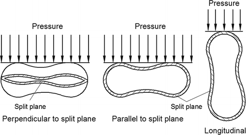
If the peanut stiffness is known, by releasing a mass from a known height, it will be possible to obtain the load to be applied on hulled peanut, maximum deformation, and pressure. Thus, in order to get force versus deformation curves, the whole pods were compressed in loading positions in three directions, longitudinal, parallel, and perpendicular to split plane () by using compression apparatus shown in .
Figure 2 Free compression test apparatus. 1, main body; 2, handle; 3, moving platform; 4, fixed platform; 5, deformation indicator; 6, precision deformation indicator; 7, specimen.
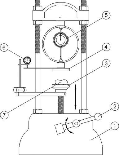
With the rotation of the handle (2), the platform (3) moved upwards and the peanut on the moving platform was subjected to compression between the moving platform and the fixed one. At this point, the deformation of peanut was read by the indicator (6) with an accuracy of 0.01 mm. By means of the indicator (5), amount of deformation, x, in mm together with a knowledge of spring constant of the loading ring, k′ (7) (k′ = 490.5 Nmm−1), the force, F, in N applied on the peanut was computed by EquationEq. (6):
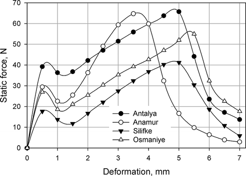
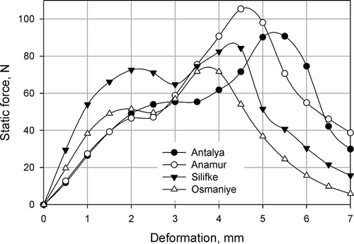
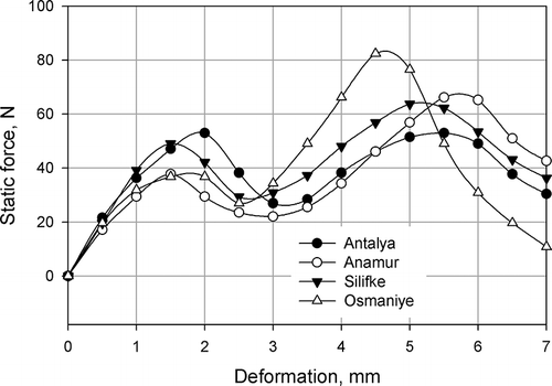
During the tests, readings of the deformation indicator (5) corresponding to every 0.5 mm deformation of a second indicator (6) were recorded. Hence, the force applied on peanut and the relevant deformation was determined. These data were used to plot force versus deformation curves (Figs. ). As observed in figures, the curves have some linearly elastic parts up until a bio-yield point and go into the nonlinear plastic region. These curves are similar to those given by Mohsenin.Citation[15] Thus, the slope of linear parts of curves that continued until bio-yield point was assumed as stiffness of the peanut, which is needed in the impact tests. The purpose here was to calculate the stiffness values as presented in .
For impact tests, an experimental set-up in which the drop height and the magnitude of weight could be varied was designed. It was a closed system to guide the drop weight vertically, however, it had a small opening through which the peanut specimen could be easily placed and observed during the test (). For the longitudinal direction test, adhesive was used to hold the samples vertically.
Table 3 Stiffness (Nmm− 1) of the whole pod
Figure 6 Impact test mechanism. 1, body; 2, top cover; 3, metal bar; 4, hammer; 5, fix plate; 6, nut; 7, specimen.
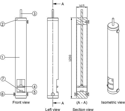
Wood, rubber, and steel were chosen as material of a moving surface, which applied force on the peanut. As a fixed surface, steel and iron grates (solid part 10 mm, void part 10 mm) were used. From each peanut variety, 285 peanuts were marked with a pen and placed on a cardboard for determining their geometric data, including projected areas and other dimensions. The dimension measurements were done by taking the scaled photocopies of the marked samples of cardboards on milimetric papers. After obtaining suitable drop height, the marked peanuts were tested and their final conditions were recorded at the end of the tests.
RESULTS AND DISCUSSION
In the impact tests, peanuts were broken by different masses that were made out of different materials. Different drop heights and two loading positions, namely, parallel and perpendicular to split plane, were used. The tests were repeated five times for each variety. The impacting surface-fixed material pairs causing breakage steel-steel, wood-steel, rubber-steel, wood-iron grate, and rubber-iron grate combinations were used. Here, the first one indicates the moving mass material while the second one stands for the fixed surface material. In addition, during the tests, peanuts were placed on the iron grate at two positions, namely, parallel and perpendicular to grates. It was thought that at longitudinal position, due to the physical contact conditions only steel-steel combination could express the material effect, so the number of tests was limited to 15 for each variety.
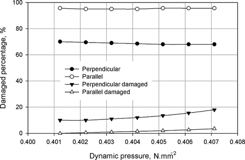
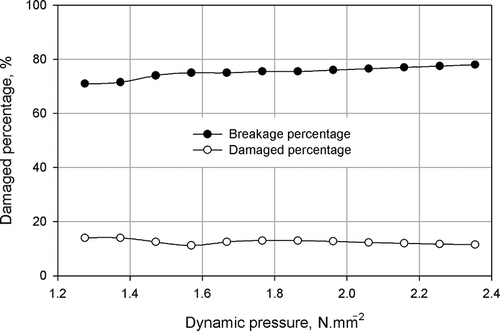
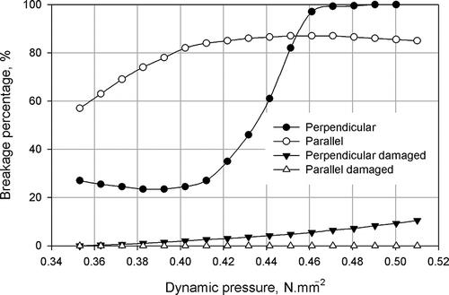
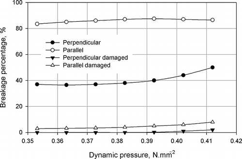
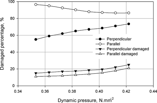
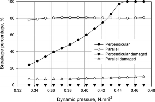
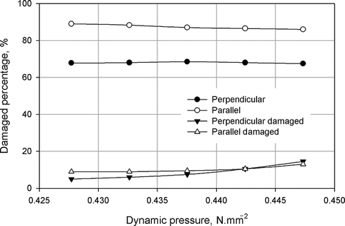
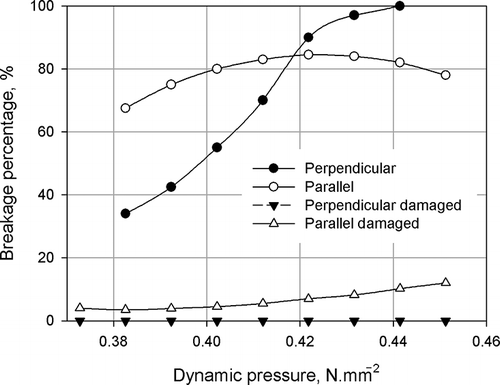
In order to evaluate these data, a computer program was written based on FORTRAN programming language. The inputs of the program were projected areas, initial length along loading direction, loading position, surface pairs, peanut varieties, stiffness, drop heights, mass values, and test observations of hulled peanut and kernel (released, not released and damaged) concerning 1140 marked peanuts samples. The outputs of the program were average dynamic pressure, breakage percentage, damaged percentage, speed at impact, dynamic force, magnitude of gap, and maximum deformation and energy at impact. From these outputs, the graphs according to surface material and loading positions were plotted in Figs. by taking the average of breakage and damaged percentage values of four varieties corresponding to dynamic pressure.
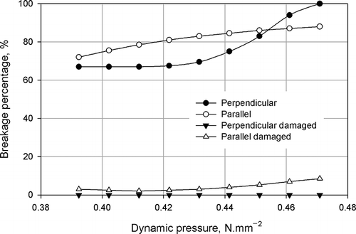
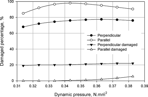
As seen in the figures, the breakage and damaged percentages increase with increasing dynamic pressures. However, it was observed that low dynamic pressures (i.e., 0.4 Nmm−2), for rubber-iron grate ( and ) and steel-iron grate ( and ) caused greater breakage percentage at impact parallel to split plane than those of perpendicular to split plane. Furthermore, in the case of steel-steel (), wood-steel (), wood-iron grate ( and ), and rubber-steel () combinations, impact at parallel to split plane also led to greater breakage percentage than that of perpendicular position. The effective dynamic pressure at longitudinal position (1.2–2.4 Nmm−2) () turned out to be noticeably larger than that for the other two loading positions. It is interesting to note that if the dynamic load causes breakage before the maximum deformation reaches gap dimension, the damage to the kernel becomes zero. When the curves are evaluated together, it can be said that less than 10% kernel damage was determined in the test whereby the iron grate was used. This result shows that use of an iron grate in a shelling machine is the most suitable decision, as far as the method of impact is concerned.
For the broken peanut under impact, larger energy and speed at impact, dynamic force, and deformation are necessary at a longitudinal loading position when compared with the other two loading positions (). The quantities in the first two rows look very similar possibly due to the geometric shape of the pod whereby peanut cross section perpendicular to long axis is approximately circular.
Table 4 Maximum and minimum values causing damage for shelling of peanut by impact
The quantities of gap and deformation values given in are suitable for checking damaged percentage. If the maximum deformation is greater than the internal gap, damage to the kernel will occur. Also, the speed and energy at impact are essential quantities for determining power requirements and working conditions of the shelling machine.
CONCLUSIONS
The major findings of the study can be summarized as follows:
| 1. | The stiffness of peanut pods for all varieties has been determined in the range of 2.560–4.060, 3.180–4.150, and 3.167–7.500 Nmm−2 for loading positions of perpendicular to split plane, parallel to split plane, and longitudinal, respectively. | ||||
| 2. | The minimum and maximum energy requirement values have been changed in the intervals 32.8–79.6 Nmm for perpendicular and parallel to split plane, 0.26–0.72 and 72.1–80.2 Nmm for longitudinal. | ||||
| 3. | The highest working speed for shelling has been determined at longitudinal position. The working speed values ranged between 1085 and 1980 mms−1. | ||||
| 4. | The maximum deformation value has been observed at loading position of perpendicular to split plane. These values have been found to vary from 4.07 to 8.05 mm. | ||||
| 5. | The gap values have been observed in the intervals 4.05–8.15 mm for perpendicular to split plane and 4.11–8.15 mm for parallel to split plane. | ||||
| 6. | The dynamic force has been determined between 13.37–25.84, 14.85–26.12, and 21.78–35.08 N for perpendicular to split plane, parallel to split plane, and longitudinal, respectively. | ||||
| 7. | The dynamic pressure variations have been observed in the range of 0.23–0.82 Nmm−2 for perpendicular to split plane, 0.26–0.72 Nmm−2 for parallel to split plane, and 1.00–2.40 Nmm−2 for longitudinal. | ||||
With these data, the design of machinery processing peanut can be carried out fully on quantitative rather than qualitative grounds and the optimum operating conditions could be estimated as well. However, further studies on impact resistance of peanut can be realized by taking into account the moisture content at different levels. Moreover, more varieties of peanut samples and more material pairs can be considered in further experiments.
REFERENCES
- Woodroof , J.G. 1983 . Peanuts Production, Processing and Products , 3rd , 139 – 151 . Avi Publishing Co. Inc.: Westport, CT .
- Güzel , E. , Akçalı , İ. D. , Mutlu , H. and İnce , A. 2005 . Research on the fatigue behaviour for peanut shelling . Journal of Food Engineering , 67 : 373 – 378 .
- Güzel , E. , Akçalı , İ. D. and İnce , A. 2007 . Behaviour of peanut bulk under static loads . Journal of Food Engineering , 80 ( 2 ) : 385 – 390 .
- Akçalı , İ.D , İnce , A. and Güzel , E. 2006 . Selected physical properties of peanuts . International Journal of Food Properties , 9 : 25 – 37 .
- Dursun , İ.G . 1997 . “ Determination of the shelling resistance of some products under the point load ” . In Proceedings of National Symposium on Mechanization in Agriculture, 17--19 September , 950 – 957 . Tokat , , Turkey : in Turkish .
- Braga , G.C. , Couto , S.M. , Hara , T. and Neto , J.T.P.A. 1999 . Mechanical behaviour of macadamia nut under compression loading . Journal of Agricultural Engineering Research , 72 : 239 – 245 .
- Gupta , R.K. and Das , S.K. 2000 . Fracture resistance of sunflower seed and kernel to compressive loading . Journal of Food Engineering , 46 : 1 – 8 .
- Olaniyan , A.O. and Oje , K. 2002 . Some aspects of the mechanical properties of sheanut . Biosystems Engineering , 81 : 413 – 420 .
- Vursavuş , K. and Özgüven , F. 2004 . Mechanical behaviour of apricot pit under compression loading . Journal of Food Engineering , 65 : 255 – 261 .
- Slay , W.O. 1976 . “ Damage to peanuts from free fall impact ” . In Agr. Res. Ser , USDA, National Agricultural Library, USA .
- Turner , W.K. , Suggs , C.W. and Dickens , J.W. Damage to peanuts and its effects on germination, seedling development and milling quality . Transactions of the ASAE 1967, 10(2) , 248 – 251 .
- Shigley , J.E. 1963 . Mechanical Engineering Design , 631 NewYork : McGraw-Hill Book Co .
- Shigley , J.E. and Mischke , C.R. 1989 . Mechanical Engineering Design , 5th , 779 NewYork : McGraw-Hill Book Co .
- Akçalı , İ.D . 1989 . Yerfıstığının Sınıflandırılması ve İç Fıstığın Çıkarılması (Classification and Decortication of Peanuts) , 93 Adana : Final Report, Tübitak Project No: TOAG-580 . in Turkish
- Mohsenin , N.N. 1970 . Physical Properties of Plant and Animal Materials , Vol. 2 , 734 New York : Gordon and Breach Publishers Inc .
