
Abstract
Biological material is exposed to different type loads during the harvesting, sorting, and transport. The contact with the hard element of the box or the harvester causes damage to the internal structure. Long-term static loads and hitting by another carrot root are the most common type of mechanical damage occurring in the post-harvest process. Because of the characteristic shape of agricultural products, compression force focused on a small area. The main purpose of this study was to determine the discrete model of carrot root as well as to verify it based on the displacement distribution. For determining an experimental model, the collected data were statistically processed. To verify the obtained model, the COSMOS/M software was applied. As a result of this study, a calculation model was presented, which allowed the assessment of surface pressures on the carrot root area, which occurred during the contact with different shaped elements in selected phases of technology process.
Introduction
Biological materials, such as vegetables and fruits, are being exposed to dynamic and static loads during harvest, transport, and sorting. Long-term static force concentrated on a small area of apple surface, as well as hit against another fruit or element, results mostly in permanent deformation of the apples[Citation1,Citation2]. Hyde[Citation3], Kabas[Citation4], Komarnicki, et al.[Citation5], and Thompson[Citation6] conducted studies, consisting in assessing of mechanical damage including agricultural products, especially apples, tomatoes, and peaches. Based on the experimental model, they described and classified the most common types of the fruit damages in relation to the acting force[Citation7–Citation11]. Studman[Citation12,Citation13] and Pang, et al.[Citation14], besides the static load, assessed the bruise resistance of fruit during storage.
Many researchers[Citation15–Citation18] set a critical load and established proper conditions to determine it. Review of the scientific literature confirms that earlier studies were not allowed to implement them into practice. Very often, exceeding the permissible threshold of resistance caused a mechanical damage of fruit and led to the first phase of the fermentation process. Holt and Schoorl[Citation19], Kitthawee et al.[Citation20], Rodriguez et al.[Citation21], and Wenian, et al.[Citation22] conducted a study aimed at the assessment of biochemical enzymes which cause the fermentation process. According to Sojak[Citation23], for determining a method which allows the assessment of the mechanical damage during storage, at first the mechanical properties as well as the size of zone should be described, on which the maximum force was focused. Until now, a problem of the mechanical damage on contact surface in fruit was analysed only for apples.
Nowadays, most researchers focus on assessment of changes in the contact area between apples and testing sensor under external force[Citation24–Citation28]. They confirmed that for determining the mechanical damage of fruit, the shape and characteristic parameters of the test object should be defined. Usually, a modelling phase includes the collection of reliable data and identification a process which will be described by experimental model. Dintwa et al.[Citation29], Kobyłka and Molenda[Citation30], Li et al.[Citation31], Petrů et al.[Citation32], Van Zeebroeck et al.[Citation33–Citation35], and Yousefi et al.[Citation36] applied a computer model to analyse the boundary values of the compression force concentrated in a small area.
Biological material is made of characteristic anatomic forms of the cells which reduce the relationships between forces acting on contact plane. The first implementation of the finite element method including apples was conducted by Lu and Abbott[Citation37] and Puri and Anantheswaran[Citation38]. The authors analysed a transfer of vibrations by the fruit tissue while the apple impacts against another element or fruit. They described the force impulses on the basis of acoustic parameters of tested objects[Citation39,Citation40]. Based on the brevity of the apple tissue, the phase of fruit maturity was determined. Lewis et al.[Citation27] have built the discrete model of ‘Golden Delicious’ apple using the laser scanner. Because of the complex structure of the fruit, the tetrahedral finite element model with four nodes was applied. For comparison, the authors of previous studies [Citation37,Citation39] have determined an experimental model on the basis of isotropic properties of biological material. Abbott and Lu[Citation41] emphasised that often the difficulty in modelling is resulted from differences in mechanical properties of the tested elements (skin, flesh, core).
Dintwa et al.[Citation42] studied apple bruise area, which appears during the contact against a fixed plate as well as another apple. They applied the MSC.Marc®/Mentat® system for model determining which enabled to calculate the geometrical nonlinearity (large deformations) and material properties (plasticity) including contact stresses and open or closed slots, based on the finite element method. Van Zeebroeck et al.[Citation43] and Celik et al.[Citation44] conducted a study on the halved apple because of the symmetry of the tested object and in order to reduce a calculation time. The model of the biological material, determined on the basis of the finite element method, was presented by Wu and Pitts[Citation45]. The authors assumed that the mechanical properties of the plant tissue depend on structure and properties of the single cell. For comparison, Wu[Citation46], Grotte et al.[Citation9], and Manjunatha and Das Gupta[Citation47] emphasised that the measurement of the tissue properties and verifying analysis of them were primarily difficult.
Materials and methods
The assumptions for determining the carrot root discrete model
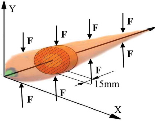
The aim of this research was the determination of the discrete model of carrot root and conducting a verifying analysis which is based on displacement distributions. The studies included harvest, sorting, and transport processes. For determining surface pressure of the tested object, the following loading elements were applied: the flats; l1 = 3 mm, l3 = 7 mm in width, and the cylinder with R = 28 mm in diameter. The tested carrot was ‘Karotan’. Generally, this variety is harvested in October. The vegetables were purchased in Poland in Lower Silesia district. The root length ranged from 137 to 156 mm, and the diameter of the tested object was between 30 mm and 40 mm and has met the UE standards for carrots introduced by the European Commission Regulation (EC) No 730/1999 on April 7, 1999, and the changes to the standard imposed by Regulation (EC) No. 46/2003. The tested sample used in the study was disk shaped and cut between two perpendicular planes in the direction of longitudinal axis as shown in . The distance between the determined planes was 15 mm and comprised approx. 10% of the carrot root total length.
Figure 1. Method of taking a sample for the study.
For determining the carrot root discrete model, a membrane state of stress in cross-section plane () was applied. Tangential and normal stresses acting in the perpendicular direction to the flat plane were ignored. The authors assumed that the force acts through a cross-section plane. Based on the analysis of the geometrical characteristic of the test material, the following assumptions were adopted: the core diameter - φr = 15 mm, outer diameter of the carrot root - φk = 30 mm, and the thickness (h) of cambium was 1 mm.
Figure 2. Geometrical disc-type model – the load and the boundary conditions.
After an analysis of the carrot strength properties, the authors decided to implement the anisotropy of biological material to the experimental model and adopted the parameters listed in .[Citation48] They took into consideration the mechanism of large deformation occurrence and the problem of surface pressure which causes a damage in the internal structure of carrot root. This issue was solved by the use of one-node contact elements in a form of nodal line.
Table 1. Parameters used to the FEM model building - COSMOS/M.
shows mean values as well as the standard deviation (SD) of stresses which ranged from 0.17 to 0.59 MPa for the modulus of elasticity E and 0.006 to 0.012 for Poisson’s ratio ν. The maximum value of the stress in the tested sample was 0–0.8 MPa. The value of the elastic modulus E on the basis of tangential method was determined and presented on the graph of stress expressed as deformation function obtained from compression test. For the studies, the cylindrical cross-section samples with a diameter of 8 mm and the length of 7 mm were taken and compressed by the INSTRON 5566th testing machine. The Poisson’s ratio was calculated on the basis of the Videoekstensometer ME-46, which allowed for non-contact measurement of sample’s deformation characterised by similar size. The loading elements were made of steel (E = 2.1 E5 MPa, ν = 0.3) in disc form. The stiffness of the tested material ensured a deformation at a low level in comparison with deformation of the carrot root. The experimental model was loaded under force acting in the radial direction through the top loading element ().
Figure 3. Geometrical disc-type model – the load and the boundary conditions.
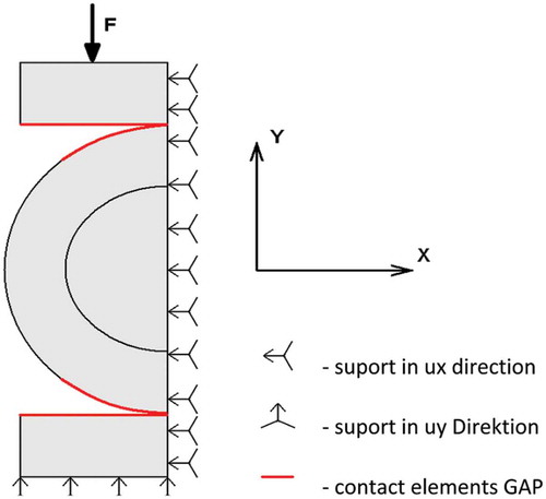
The authors conducted a study on the halved carrot root due to the symmetry of the tested object and in order to shorten the calculation time. It was assumed that the bottom loading element was fixed by reducing all the degrees of freedom. The half of the cross-section carrot root and the top loading element were supported in the X direction to enable the movement of these elements in the direction of the Y axis.
The discrete model
For determining the discrete model, the flat and triangular finite elements were characterised by three nodes, called TRIANG 2D – for the core layer and the flat rectangular elements called 2D PLANE – for a layer of bark and cambium. The problem issue of contact pressures, which have not included the friction between the contact elements, was solved by the use of special instrument called GAP[Citation49]. As a result, a three-layer discrete model was built, which included: 576 PLANE 2D elements of core layer, 72 PLANE 2D elements of cambium layer, 1098 TRIANG elements of the core layer, 1456 nodes and elements having 2912 degrees of freedom. The conducted nonlinear analysis was performed on the basis of: boundary conditions, contours of displacement ux in the direction of the X axis and uy in the direction of the Y axis on the whole plane of the tested model. The COSMOS/M program was applied to determine distributions of displacement in two mutually perpendicular cross-sections. For determining displacements, the Electronic Speckle Pattern Interferometry (ESPI) programme was used by Gerhard and Busse[Citation50]. This system allows to determine the contours of displacement on the whole surface of the tested sample as well as distributions of displacements along the selected sections.
This study was aimed at determining the distributions of displacements using speckle pattern interferometry and was carried out in the Department of Biomedical Engineering and Experimental in the Mechanics Institute of Design and Operation in Wroclaw University of Technology. The test instrument enabled the measurement of displacements with high precision and in non-contact way including three directions on the whole cross-section area. This instrument was equipped with the head, which allowed for the assessment of displacement by speckle pattern interferometry (ESPI 3D system). Such a head consisted of coherent light source (two laser diodes of 50 mW) and the optical system which enabled the separation of the optical beam into objective and reference beams ().
Figure 4. Optical system for measurement of displacement using ESPI.
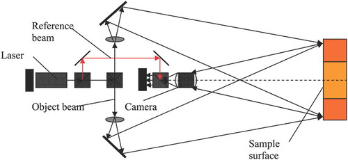
The objective beam, due to the system of prisms, was divided into four mutually perpendicular to each other beams, which after the reflection against the mirror surface, was directed to the test object, then scattered on its surface, and put on the lens of a digital camera with high resolution. The loading element was equipped with an extension arm on which a measuring head was placed. This instrument was put on the table used for the holographic test, which enabled the insulation of the test object against outside disturbance. The tested carrot root was pre-loaded under force of F ‘= 2.5 Nmm−1, which constituted about 10% of the critical load. It was noted that during storage the load was evenly put along the entire length of the root and corresponded to the real values of the load on the whole root and amounted approx. 400 N. After the constant phase, the holographic image has been recorded, and as a consequence, the authors have increased the load by ΔF ‘= 0.02 Nmm−1. The presented method allows for performance of the maximum force, above which the displacement values exceed the measuring range of the ESPI system. After 30 s needed to regulate a new image of speckle pattern, a renewed record was conducted. Because of the interference of holographic images, the system of fringes was obtained. Firstly, the obtained results were converted into digital signals and processed by a computer equipped with testing system. As a result of the electronic processing, an optical holographic image was obtained, on which the displacement contours in three perpendicular directions were presented: in direction of the vertical Y axis, in direction of the horizontal X axis, and Z direction which was perpendicular to the plane of the tested section. Based on these results, the verifying analysis of the discrete model was conducted.
Results and discussion
During the harvest, sorting, and transport, the carrot roots are exposed to contact with the various shaped elements. The most popular include flat surface, flats in various widths, and cylindrical elements. Hence, the authors decided to carry out the verification test on the basis of displacement distributions, which concerned a working part of the flat or cylindrical shaped loading head characterised by a width of l1 = 3 mm (), 3 = 7 mm () for flats, and the radius R = 28 mm () for cylindrical shape.
Figure 5. (a) Real object – measurement of ESPI (b) Disc model – MES. Contours of uy displacement obtained during the contact with the flat l1 = 3 mm.
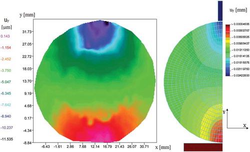
Figure 6. The uy displacement distributions in the Y direction obtained during the contact with a flat l1 = 3 mm.
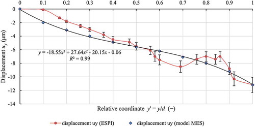
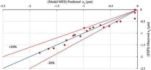
Figure 7. Dispersion of the obtained results of the displacement uy (ESPI) in comparison to the predicted FEM values, during the contact with the flat l1 = 3 mm in width.
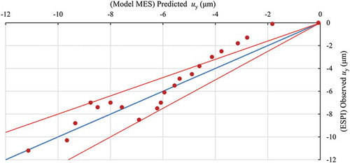
Figure 8. (a) Real object – measurement of ESPI (b) Membrane model – FEM Contours of uy displacements obtained during the contact with the flat l2 = 7 mm in width being under load.
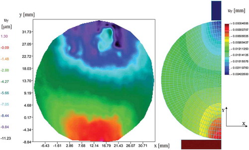
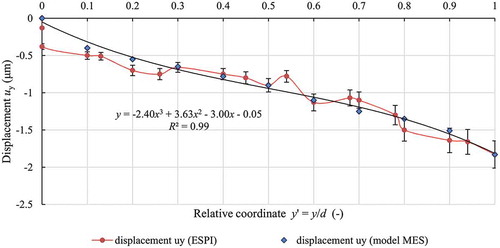
Figure 9. Distributions of displacements uy in the Y direction obtained during contact with a flat (l2 = 7 mm in width).
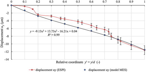
Figure 10. Dispersion of the measured values of the displacement uy (ESPI) compared to the predicted values FEM during contact with a flat (l1 = 7 mm in width).
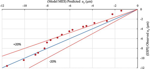
Figure 11. Contours of uy displacements obtained during the contact with the flat l2 = 7 mm in width being under load.
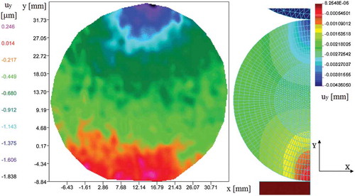
shows the contours of displacements uy obtained from the experimental studies () and on the basis of the discrete model () during acting of the flat element (thickness g = 3 mm) against surface of the examined object. At the point of impacting force, the uy displacement in the Y direction reached the maximum value. The zone of clear visible local influence ended at the contact point of the core and the bark. On the total section plane, a displacement was zero It was confirmed by the contours of displacement performed along the vertical axis of the tested object (). The determination of the relative coordinate was performed in order to compare the experimental results with the model. For this purpose, the centre of the coordinate system into the left bottom corner (on the images of the ESPI) was displaced, and results by the real diameter of the tested sample (y’ = y/d)- were divided. The studies were conducted in five repetitions.
Matching the model to results obtained in the experimental studies in was presented. This image clearly shows that experimental results of displacements above 4 µm correspond with the model in the range of ± 20%. The poor compatibility was observed only for less than 4 µm deformation values, put especially on the bottom support and resulted from friction phenomenon occurrence between the support arm and tested sample as well as impact of flat’s sharp edges.
The relative error ranged from 0 to 13.18%, and mean value of displacement was 8.19%. In analysed section, the cambium layer has not influenced the displacement uy. The average difference between the real values in comparison obtained from model was 0.92 μm and constituted about 9% of the maximum displacement values ().
Table 2. Comparison of displacement distributions uy in the direction of the Y axis ().
A slight difference in displacement distribution on tested section plane under impact flat element (thickness g = 7 mm) was observed (). A displacement was visible on the whole section plane (lack of displacement was shown only at the bottom fixed jaw). On symmetrical section plane, which was cut through the horizontal axis, the displacements were characterised as constant. Sharp edges of test element clearly influenced the displacements by narrowing their zones towards the point impacting force. shows a perturbation on the graph of course especially in the contact area between the core and the bark.
Matched model to the experimental data was in range of ± 20%, whereas the test object was under load of the flat element, characterised by 7 mm in width (). The conducted analysis showed a greater match in the area of support arm due to the occurrence of friction without influence of flat sharp edges on test sample. The relative error was constant for the whole section plane and ranged from 0 to 13.09%, whereas the mean value was 3.31%. The average difference between real and obtained from the model values was 0.39 μm and constituted about 3% of the maximum displacement (). The results of the above studies confirm that matching this model to the experimental data was more accurate than in other tests.
Table 3. The comparison of displacement distributions uy in the direction of Y axis ().
shows the contours and distribution of uy displacement for the carrot root cross-section plane at the contact point between tested sample and the cylindrical shaped plane for R = 28 mm. Because of the round shape of contact surface, a line course for constant value has been changed. These lines were located in perpendicular directions to the acting force. The conducted analysis indicated that at the contact point between the core and the bark, disturbances in course of displacement were observed. Such a phenomenon was observed on the graphs describing displacement uy formed along the axis covered by acting force ().
Figure 12. Displacement distributions uy in the direction of Y axis obtained during the contact with cylindrical element of R = 28 mm.
The most effective match model to experimental data was obtained for the interaction of tested object with the cylindrical surface of R = 28 (). In this case, a clear compatibility was observed only in the area of support arm (deformation level was 0.1 μm), whereas on the rest surface exceeded ± 20%. The analysis of displacement for the obtained sample has not been conducted due to the shape of the flats impacting surface. For obtained load range (up to 2 μm), the error was relatively constant on the whole section and ranged from 0 to 17.7%, whereas the average value was 4.8%. The mean difference between the real values and obtained on the basis of the model was 0.09 μm and constituted 4.5% of the maximum displacement values ().
Table 4. The comparison of displacement distributions uy in the direction of Y axis ().
Figure 13. Dispersion of measured displacement uy values (ESPI) in the comparison to the predicted MES model values during the contact with cylindrical loading element of R = 28 mm.
The authors compared the obtained results to the experimental studies conducted by other researchers. The elasticity modulus for a single cell corresponded to the parameter determined by Steudle and Wieneke[Citation51]. Wu and Pitts[Citation45] showed a 3D model of the finite element method, allowed for maintaining a real shape of the flesh cells, which was determined by microscopic measurements and then tested. The discrete model of the cell’s peel was performed with the use of the 224 thin and parabolic shell shaped elements. The applied MARC™ (MARC Analysis Research Corporation) system enabled a non-linear analysis and assessed a reaction of single cell subjected to various types of loads.
Lewis et al.[Citation27] determined the surface pressure on the basis of the ultrasonic waves. Based on these studies, it was found that the distribution of pressures created along the contact plane was significantly different from that obtained through the use of other methods. For determining the surface pressures, on the whole length of contact zone, the Hertz formula was proposed, which caused significant differences between the experimental data and the real values[Citation52]. The finite element method is recognised as one of the most popular programmes used in determining an experimental models including various type of tested materials. The use of the finite element method in assessing the biological material properties develops some problems due to the delicate structure of flesh and tissue. Generally, the biological material has an anisotropic structure and is characterised by a low elasticity modulus and high level of Poisson constant. In addition, the layered structure and the strength of the test material depend clearly on a place from which the sample was taken. Other authors confirmed that properties of the biological material changed over time and the mechanical parameters of the plant tissue strongly depended on the water content[Citation53–Citation55].
Conclusion
The problem of contact pressure including fruit as well as vegetables occurred generally during harvesting, sorting, and transport. The force concentrated in a small area may cause serious damages, even though the total value of the acting force is low. A computer analysis, conducted on the basis of elasticity and plasticity theory, has not provided reliable data and developed often many errors. The use of the Hertz formulas in determining the allowable limit of surface pressures for biological materials negated the assumptions on which they were formulated. From a theoretical viewpoint, the analyses of friction which occurred in the contact zone as well as mechanical deformation between agricultural products appeared impossible. The effective calculation process, required to meet some basic procedures, joined with technical capability of the tested programme.
First of all, it was necessary to conduct an analysis of the tested materials on the basis of reliable data which concerned their mechanical properties and phenomena including a modelling process. For this purpose, the authors evaluated the density, the modulus of elasticity E, and Poisson’s ratio ν in three mutually perpendicular directions. Secondly, the verifying analysis of the discrete model was carried out using a few parameters that have not been considered as aim of this study. The test was performed based on the displacement of selected points, placed on the cross-section plane and determined by ESPI system. Because of the applied testing method, the load range for carrot root was reduced to 2.5 Nmm−1. Thirdly, the determination of contours, distributions, and parameters is described as a purpose of this study, for example, the contours of stresses σx, σy, σz, the contours of displacements ux, uy, uz, and surface pressures. The verification of the finite element model using the COSMOS/M system, based on the displacement distribution, corresponds to the absolute values, obtained from the study. The relative error resulting from the comparison between the experimental data of the uy displacement and that obtained during modelling has not exceeded 20%. The presented model can be practically applied in the assessment of damages in biological material caused by various types of loads on which the carrot is exposed during harvesting, transport, sorting, and storage.
Acknowledgements
The authors gratefully acknowledge the financial support provided by the Wrocław University of Environmental and Life Sciences. The authors thank kindly the Wrocław University of Science and Technology for help in collecting experimental data.
Related Research Data
References
- Li, Z.; Colin, T. Quantitative Evaluation of Mechanical Damage to Fresh Fruits. Trends in Food Science & Technology 2014, 35, 138–150.
- Sadrnia, H.; Rajabipour, A.; Jafari, A.; Javadi, A.; Mostofi, Y.; Kafashan, J.; Dintwa, E.; De Baerdemaeker, J. Internal Bruising Prediction in Watermelon Compression Using Nonlinear Models. Journal of Food Engineering 2008, 86(2), 272–280.
- Hyde, G.M. Bruising-impacts, Why Apples Bruise, and What You Can do to Minimize Bruising. Tree Fruit Postharvest Journal 1997, 8(4), 9–12.
- Kabas, O. Methods of Measuring Bruise Volume of Pear (Pyrus communis L.). International Journal of Food Properties 2010, 13(5), 1178–1186.
- Komarnicki, P.; Stopa, R.; Szyjewicz, D.; Młotek, M. Evaluation of Bruise Resistance of Pears to Impact Load. Postharvest Biology and Technology 2016, 114, 36–44.
- Thompson, A.K. Fruit and Vegetables: Harvesting, Handling and Storage. Wiley 2007, ISBN: 9781405106191.
- Chen, P.; Yazdani, R. Prediction of Apple Bruising Due to Impact on Different Surfaces. Transactions of the ASAE 1991, 34, 956–961.
- Garcia, J.L.; Ruiz-Altisent, M.; Barreiro, P. Factors Influencing Mechanical Properties and Bruise Susceptibility of Apples and Pears. Journal of Agricultural Engineering Research 1995, 61, 11–18.
- Grotte, M.; Duprat, F.; Loonis, D.; Piétri, E. Mechanical Properties of the Skin and the Flesh of Apples. International Journal of Food Properties 2001, 4(1), 149–161.
- Roudot, A.C.; Duprat, F.; Wenian, C. Modelling the Response of Apples to Loads. Journal of Agricultural Engineering Research 1991, 4, 249–259.
- Yuwana, Y.; Duprat, F. Prediction of Apple Bruising Based on the Instantaneous Impact Shear Stress and Energy Absorbed. International Agrophysics 1998, 12, 133–140.
- Studman, C.J. Model of Fruit Bruising. In: Proceedings of the 2nd Australasian Postharvest Conference, Science and Technology for the Fresh Food Revolution, 1996, Monash University, Melbourne. Institute for Horticultural Development, Department of Natural Resources and the Environment, 241–246.
- Studman, C.J. Handling Systems and Packaging. In: CIGR Agricultural Engineering Handbook IV.3; F.W. Bakker-Arkema, Ed.; American Society of Agricultural Engineers: St. Joseph, MI, 1999, 291–340, Chapter 3.
- Pang, D.W.; Studman, C.L.; Banks, N.H. Apple Bruising Thresholds for an Instrumented Sphere. Transactions of the ASAE 1994, 37(3), 893–897.
- Gołacki, K. A Quick Method to Determine the Mechanical Condition of Carrot Roots. Acta Horticulturae 1998, 421, 259–263.
- Stropek, Z.; Gołacki, K. A New Method for Measuring Impact Related Bruises in Fruits. Postharvest Biology and Technology 2015, 110, 131–139.
- Stropek, Z.; Gołacki K. Methodological Aspects of Determining Apple Mechanical Properties During Impact, International Journal of Food Properties 2016, 19(6), 1325–1334.
- Umeda, M.; Namikawa, K. Modeling the Deformation of Cell to Loads Using Model Cell of Rubber Balk Fitted with Water. International Agrophysics 1994, 8, 597–601.
- Holt, J.E.; Schoorl, D. Package Protection and Energy Dissipation in Apple Packs. Scientia Horticulturae 1984, 24, 165–176.
- Kitthawee, U.; Pathaveerat, S.; Srirungruang, T.; Slaughter, D. Mechanical Bruising of Young Coconut. Biosystems Engineering 2011, 109, 211–219.
- Rodriguez, L.; Ruiz, M.; De Felipe, M.R. Differences in the Structural Response of ‘Granny-Smith’ Apples Under Mechanical Impact and Compression. Journal of Texture Studies 1990, 21, 155–164.
- Wenian, C.; Duprat, F.; Roudot, A.C. Evaluation of the Importance of the Cellular Tissue Geometry on the Strains Observed on Apples after a Compression or an Impact. Sciences des Aliments 1991, 11, 99–110.
- Sojak, M.; Głowacki, S. Klasyfikacja Marchwi Z Wykorzystaniem Systemu Ekspertowego. Inżynieria Rolnicza 2008, 7(105), 201–206.
- Herold, B.; Geyer, M.; Studman, C.J. Fruit Contact Pressure Distributions Equipment. Computers and Electronics in Agriculture 2001, 32, 167–179.
- Lu, F.; Ishikawa, Y.; Kitazawa, H.; Satake, T. Measurement of Impact Pressure and Bruising of Apple Fruit Using Pressure-Sensitive Film Technique. Journal of Food Engineering 2010, 96(4), 614–620.
- Rabelo, G.F.; Dal Fabbro, I.M.; Linares, A.W. Contact Stress area Measurement of Spherical Fruit. Acta Horticulturae 2001, 562, 195–200.
- Lewis, R.; Yoxall, A.; Marshall, M.B.; Canty, L.A. Characterising Pressure and Bruising in Apple Fruit. Wear 2008, 264, 37–46.
- Opara, U.L.; Pathare, P.B. Bruise Damage Measurement and Analysis of Fresh Horticultural Produce–A Review. Postharvest Biology and Technology 2014, 91, 9–24.
- Dintwa, E.; Jancsók, P.; Mebatsion, H.K.; Verlinden, B.; Verboven, P.; Wang, C.X.; Thomas, C.R.; Tijskens, E.; Ramon, H.; Nicolaï, B. A Finite Element Model for Mechanical Deformation of Single Tomato Suspension Cells. Journal of Food Engineering 2011 103(3), 265–272.
- Kobyłka, R.; Molenda, M. DEM Simulations of Loads on Obstruction Attached to the Wall of a Model Grain Silo and of Flow Disturbance Around the Obstruction. Powder Technology 2014, 256, 210–216.
- Li, Z.; Li, P.; Yang, H.; Liu, J. Internal Mechanical Damage Prediction in Tomato Compression Using Multiscale Finite Element Models. Journal of Food Engineering 2013, 116(3), 639–647.
- Petrů, M.; Novák, O.; Herák, D.; Simanjuntak S. Finite Element Method Model of the Mechanical Behaviour of Jatropha curcas L. Seed Under Compression Loading. Biosystems Engineering 2012, 111, 412–421.
- Van Zeebroeck, M.; Tijskens, E.; Dintwa, E.; Kafashan, J.; Loodts, J.; De Baerdemaeker, J.; Ramon, H. The Discrete Element Method (DEM) to Simulate Fruit Impact Damage During Transport and Handling: Case Study of Vibration Damage During Apple Bulk Transport. Postharvest Biology Technology 2006a, 41, 92–100.
- Van Zeebroeck, M.; Tijskens, E.; Dintwa, E.; Kafashan, J.; Loodts, J.; De Baerdemaeker, J.; Ramon, H. The Discrete Element Method (DEM) to Simulate Fruit Impact Damage During Transport and Handling: Model Building and Validation of DEM to Predict Bruise Damage of Apples. Postharvest Biology Technology 2006b, 41, 85–91.
- Van Zeebroeck, M.; Lombaert, G.; Dintwa, E.; Ramon, H.; Degrande, G.; Tijskens, E. The Simulation of the Impact Damage to Fruit During the Passage of a Truck over a Speed Bump by Means of the Discrete Element Method. Biosystems Engineering 2008, 101, 58–68.
- Yousefi, S.; Farsi, H.; Kheiralipour, K. Drop Test of Pear Fruit: Experimental Measurement and Finite Element Modelling. Biosystems Engineering 2016, 147, 17–25.
- Lu, R.; Abbott, J.A. Finite Element Analysis of Modes of Vibration in Apples. Journal of Texture Studies 1996, 27, 265–286.
- Puri, V.M.; Anantheswaran, R.C. The Finite-Element Method in Food Processing: A Review. Journal of Food Engineering 1993, 19(3), 247–274.
- Lu, R.; Abbott, J.A. Finite Element Modelling of Transient Responses of Apples to Impulse Excitation. Transactions of the ASAE 1997, 40(5), 1395–1409.
- Song, H.; Wang, J.; Li, Y. Studies on Vibrations Characteristics of the Pear Using Finite Element Method. Journal of Zhejiang University Science B 2006, 7(6), 491–496.
- Abbott, J.A.; Lu, R. Anisotropic Mechanical Properties of Apples. Transactions of the ASAE 1996 39(4), 1451–1459.
- Dintwa, E.; Van Zeebroeck, M.; Ramon, H.; Tijskens, E. Finite Element Analysis of the Dynamic Collision of Apple Fruit. Postharvest Biology and Technology 2008, 49, 260–276.
- Van Zeebroeck, M.; Tijskens, E.; Van Liedekerke, P.; Deli, V.; De Baerdemaeker, J.; Ramon, H. Determination of the Dynamical Behaviour of Biological Materials during Impact Using a Pendulum Device. Journal of Sound and Vibration 2003, 266, 465–480.
- Celik, H.K.; Rennie, A.E.W.; Akinci, I. Deformation Behaviour Simulation of an Apple Under Drop Case by Finite Element Method. Journal of Food Engineering 2011, 104(2), 293–298.
- Wu, N.; Pitts, M.J. Development and Validation of a Finite Element Model of an Apple Fruit Cell. Postharvest Biology Technology 1999, 16, 1–8.
- Wu, N. Modeling Apple Firmness Sensors with Finite Element Method. M.S. Thesis. Washington State University, Pullman, WA 1993.
- Manjunatha S.S.; Das Gupta D.K. Instrumental Textural Characteristics of Restructured Carrot Cubes. International Journal of Food Properties 2006, 9(3), 453–462.
- Stopa, R.; Smolnicki, T. Modelowanie Rozkładów Przemieszczeń Walcowej Próbki Bulwy Ziemniaka Przy Obciążeniu Osiowym Metodą Elementów Skończonych. Inżynieria Rolnicza 2011, 9(134), 223–230.
- Smolnicki, T.; Rusiński, E. Superelement-Based Modeling of Load Distribution in Large-Size Slewing Bearings. Journal of Mechanical Design 2007, 129(4), 459–463.
- Gerhard, H.; Busse, G. Lockin-ESPI interferometric imaging for remote non-destructive testing. Vth International Workshop, Advances in Signal Processing for Non Destructive Evaluation of Materials, Québec City, Canada, 2005.
- Steudle, E.; Wieneke, J. Changes in Water Relations and Elastic Properties of Apple Fruit Cells during Growth And Development. Journal of the American Society for Horticultural Science 1985, 110, 824–829.
- Dyląg, Z.; Jakubowicz, A.; Orłoś, Z.; Wytrzymałość Materiałów. WNT. Warszawa. 2003 ISBN: 8320428165.
- McGarry, A. Cellular Basis of Tissue Toughness in Carrot (Daucus carota L.) Storage Roots. Annals of Botany 1995, 75(2), 157–163.
- Tibäck, E.; Langton, M.; Oliveira, J.; Ahrné, L. Mathematical Modeling of the Viscosity of Tomato, Broccoli and Carrot Purees Under Dynamic Conditions. Journal of Food Engineering 2014, 124, 35–42.
- Jones, C.S.; Holt, J.E.; Schoorl, D. A Model to Predict Damage to Horticultural Produce During Transport. Journal of Agricultural Engineering Research 1991, 4, 259–272.