
ABSTRACT
To reveal the formation mechanism of a pulse-jet airflow’s cleaning effect in a filter bag, a theoretical model is built by using the theory of the gas jet and unitary adiabatic flow according to given specifications and dimensions of the bags and resistance characteristics of the cloth and dust layer. It is about the relationship between cleaning system structure and operating parameters. The model follows the principle that the flow and kinetic energy of jet flow injected into a filter bag should be consistent with the flow of cleaning airflow in the bag and the pressure drop flowing through the filter cloth and dust layer. The purpose of the model is to achieve the peak pressure of cleaning airflow, which dominates the effect of the pulse-jet cleaning process. The cleaning system structure includes air pressure in the nozzle, structure and size of nozzle, exit velocity of nozzle, jet distance, and diameter of jet cross section. Based on the condition of the cleaning system structure and operating parameters established by using the theoretical model, Fluent software is applied to carry out a numerical simulation of the jet airflow field at the nozzle’s outlet, jet airflow field between nozzle and bag top, and cleaning airflow field in the filter bag. Experimental results are used to verify the reliability of the theoretical model. They are obtained in a pilot-scale test filter with a single bag, with length 2 m and in general full-scale dimensions of the cleaning system. The results show that when any rectification measure is not installed at the bag opening, the cross-sectional area covered by the jet gas is hardly sufficient to cover the entire area of the bag opening. A large portion of the gases injected into the filter bag will overflow reversely upward from the edge due to pressure differences between the upper area and lower area inside the bag opening. This led to a serious shortage of the cleaning airflow and ar limited increase in static pressure. When a venturi-type rectifier tube is installed at the bag opening, the jet flow is converted to funnel flow for which the cross-section velocity distribution is more uniform at the throat of the rectifier tube due to the guided effects of the upper tapered pipe. Then it is transited to stressful flow below the bag opening via rectified effects of the lower dilated pipe. The results show that the gap between the static pressure of gas in the bag and the expected value is significantly reduced. The theoretical value of the nozzle diameter is enlarged to compensate for two aspects of adverse effects of cleaning airflow and energy. This is because the flow is not a purely free-form jet from the nozzle to the entrance of the rectifier tube and because the gas suffers from local resistance while flowing through the rectifier tube. The numerical simulation and experiment show that the peak pressure of cleaning airflow in the filter bag is able to reach the expected value. The results confirm that the mechanism of the pulse-jet cleaning airflow and the calculation method of the pulse-jet cleaning system structure and operating parameters offered in this study are correct. The study results provide a scientific basis for designing the system of pulse-jet fabric filters.
Implications: Pulse-jet cleaned fabric filters are commonly used for air pollution control in many industries. Pulse-jet cleaning is widely used for this purpose as it enables frequent cleaning while the filter is operating. However, the theoretical system of the forming mechanism of the pulse-jet cleaning has not formed so far. This indicates the theoretical model plays an important role in designing effective pulse-jet cleaned fabric filters.
Introduction
A bag filter plays an important role in the purification of flue gas dust because of its high collection efficiency for fine dust (Yang, Citation2000; Wilanowicz et al. 2013). To keep a bag filter’s smooth and efficient operation, appropriate material properties of the filter cloth should be chosen according to the flue gas first, and then a cleaning system that has a good cleaning effect should be designed. The pulse jet is most widely used as a mode of cleaning. Scholars from home and abroad are conducting extensive research around the dominant motivation and influencing factors of dust-layer exfoliation. The pulse-jet cleaning process is very complex; the dominant motivation may be a single indicator or a combination of index peak pressure, pressure impulse, reverse air speed at which the pulse-jet airflow is formed in the bag, and surface acceleration of the filter cloth (Humphries and Madden, Citation1983; Sievert and Löffler, Citation1989; Piekaar and Clarenburg, Citation1967; Lo et al., Citation2010; Kanaoka and Kishima, Citation1999). Moreover, there are many factors that can influence the motivations. They are air pressure, nozzle diameter, jet distance, the form of bag opening, specifications and dimensions of the bags, mechanical properties of the cloth, resistance characteristics of the cloth and dust layer, cleaning offline or online, and many other factors such as the structure characteristic of the bag cage (Schiller and Schmid, Citation2015; Choudhary and Mukhopadhyay, Citation2013; Pham et al., Citation2012; Lu and Tsai, Citation1999; Saleem et al., Citation2011). A clear definition of the dominant motivation causing dust layer stripping in the process of pulse-jet cleaning dust and a clear understanding of the intrinsic relationships between the structure and operation parameters involved in the loaded bag are poor. Currently, existing research mostly focuses on examining one of the various factors acting on the cleaning effect or certain related motives (Hemerka et al., Citation2001; Kurose et al., Citation2003; Yan et al., Citation2013; Tsai and Lu, Citation1998; Chen, Citation2001; Leubner and Riebel, Citation2004; Schildermans et al., Citation2004). So far, a theoretical system for the formation mechanism of pulse-jet cleaning has not yet been formed, resulting in the lack of a mature design method for the cleaning system, which has a decisive effect on the efficiency of the fabric filters.
Peak pressure of the cleaning airflow is regarded as a representative index of intensity of the cleaning effect. Depending on the given specifications and dimensions of the bags and resistance characteristics of the cloth and dust layer and the expected peak pressure (2500 Pa or 4500 Pa), a theoretical model of a relationship between the maximum peak pressure of pulse-jet cleaning airflow formed in the filter bag and the system structure and operating parameters of the pulse-jet cleaning airflow is established by using the theory of gas jet and unitary adiabatic flow. It follows the principle that the flow and kinetic energy of jet flow injected into a filter bag should be consistent with the flow of the cleaning airflow in the bag and the pressure drop of the dust layer flowing through the filter cloth and attaching to the surface. Finally, taking the achievement of the setup efficiency of removing the dust layer from the bags as the target and the peak pulse pressure obtained within the bags as the leading cause plays an important role in designing effective pulse-jet cleaned fabric filters.
Theoretical model
Formation mechanism of the peak pressure of pulse-jet cleaning airflow in the filter bag
According to the Darcy formula, the peak pulse-jet pressure obtained within the bag and radial reverse flow speed for online pulse-jet cleaning conditions should be
where is the flow of cleaning airflow in the bag corresponding to the peak pressure, m3 s−1;
is the diameter of the filter bag, m;
is the length of the filter bag, m;
is the peak pressure of cleaning airflow within the bag, Pa;
is the velocity peak of radical reverse flow speed of cleaning flow in the bag, m s−1; and
is maximum velocity peak of reverse flow over the average value of flow velocity over the cleaning bag length,
. If the cleaning airflow has the maximum peak pressure and the distribution of reverse flow speed is uniform over the bag length, it can be approximated that β = 1;
is the axis mean of radial reverse flow speed of cleaning airflow in the bag at the time of peak pressure formation, m s−1;
;
and
are the permeability of the filter cloth and that of the dust layer, respectively, m2;
and
are the thickness of the filter cloth and that of the dust layer, respectively, m;
is the equivalent permeability of negative dust cloth, m2;
is the equivalent thickness of negative dust cloth, m;
is the dynamic coefficient of viscosity of cleaning airflow, Pa-s; and
is the resistance coefficient of cloth and dust layer, Pa s m−1, which mainly depends on the filter bag dust load and resistance characteristics of dust layers.
Because the space size of a nozzle on the purge tube is much smaller than the space size of an upper box, the compressed air expands through the nozzle, forming a pulse jet of primary air. In the near-field region around the pulse jet, the secondary air entrains the pulse jet as it travels toward the venturi. Consequently, the airflow in this process can be regarded as a quasi-free jet for online pulse-jet cleaning.
The flow and average kinetic energy of the jet at the critical section
According to the jet-flow theory, a general rule among the jet distance S, nozzle diameter , and the opening diameter D of filter bag can be obtained. As shown in , converting the jet distance into jet angle, the geometric relationship between jet angle
and jet distance S can be expressed by the following equation:
Figure 1. A schematic diagram of the jet angle.
where is the jet angle, D is the opening diameter of filter bag,
is the nozzle diameter, S is the jet distance,
is the coefficient of experiment, and
is the coefficient of turbulence,
= 0.076.
According to eqs 4 and 5, it is easy to establish the relationship among the jet distance S, nozzle diameter, and opening diameter D of the filter bag:
In addition, when the jet reaches into the critical section of bag opening, the formula for the airflow Q can be deduced according to the jet-flow theory. The process is as follows:
where is the flow of nozzle outlet,
.
According to eqs 6 and 7, it is easy to establish the equation for the airflow:
The formula of average kinetic energy of the critical section can also be obtained according to the jet-flow theory:
where is the average kinetic energy of the critical section, R is the radius of the jet critical section, v is the velocity of the y point in the boundary layer of the same section,
is the axial velocity, and
is the flow velocity at the nozzle exit.
According to eqs 9 and 10, the average kinetic energy of the critical section can be expressed by the following equation:
Because the axial wind speed of cleaning airflow is small in the filter bag, the flow resistance of cleaning airflow will be ignored. If effective measures can be taken to introduce the jet flow into the filter bag completely, the energy of jet gases entering the bag can make up for the losses of gas resistance formed due to its own filtration. However, the energy is also sufficient to overcome the resistance losses of the radial cleaning airflow through the bag. According to the relationship between radial reverse flow speed of cleaning airflow passing through a loaded filter bag and static pressure, which is characterized by the Darcy formula, in order to achieve the proposed peak pressure of cleaning airflow in the bag for a particular size of filter bag and resistance characteristics, the flow injected into the filter bag and the average kinetic energy must satisfy
where is the gas filtration velocity of filter bag and
is the energy difference of the gas at upper box of filter bag relative to the gas at the middle box.
According to eqs 1 to 14, between the structure and operating parameters of the injection system exists a mutual restraint link as shown here:
Based on the preceding analysis, a theoretical model of a relationship between the maximum peak pressure of pulse-jet cleaning airflow formed in the filter bag and the system structure and operating parameters of the pulse-jet cleaning airflow is established by using the theory of gas jet and unitary adiabatic flow according to given specifications and dimensions of the bag and resistance characteristics of the cloth and dust layer and the expected peak pressures (2500 Pa or 4500 Pa).
Air pressure and type of nozzle
Due to the size of the injection nozzle being much smaller than that of the purge tube, the compressed gas inside the nozzle is considered to be in a state of stagnation. According to the unitary theory of adiabatic gas flow, the relationship between the velocity of the airflow at the exit and static pressure of the compressed gas inside the nozzle should be
If the gas velocity at the exit of the nozzle is at supersonic speed, then the structure size of a Laval tapered tube is designed. If not, the structure size of a reducing pipe is designed (see ), and the length is taken as 30 mm. According to eqs 15 to 18,
can be calculated, which is the theoretical value of the nozzle.
Figure 2. The geometric model of the nozzle: (a) structure size of Laval tapered tube; (b) structure size of reducing pipe.
The throat section size of the Laval tapered tube should satisfy eq 20; the contraction angle of the tapered tube is taken as 30°, the length is taken as
, the opening angle of the expansion section
is taken as 10°, and the expansion section
is determined according to formula 21:
The effect and structure of a rectifier tube at the entrance of a filter bag
The kinetic energy of the jet cross-section attenuates from the center to the edge largely, and the diameter of the critical section through which the airflow jet enters is typically much smaller than the diameter of the bag opening, which is calculated by using eq 16. If rectification measures are not taken, the jet flow must form a local vortex at the bag opening. The unnecessary losses of energy flow lead to a considerable part of the gas at the edge of the jet cross section losing the ability to enter the interior of the bag and the pressure of the cleaning airflow in the bag being reduced. There are three benefits for adding a venturi-type rectifier tube in the bag opening. The first is that the upper exit size of the venturi is close to the size of the jet cross section, which contributes to accepting the jet-pulsed air. The second is that the pulsed air in the jet flow state, which has huge axial velocity and small edge velocity, has a more uniform cross-section velocity distribution due to the venturi. The third is the rectification measure fully converting the kinetic energy of the jet airflow into pressure energy of the cleaning airflow in the bag. The shape of the rectifier tube is shown in , where D is the diameter of the jet critical section, calculated using formula 16. The distance from the nozzle to the critical section is calculated using formula 17. To prevent the loss of jet airflow due to deviation between the jet axis and the center of the bag opening, the diameter of the rectifier’s upper exit D’ is made 1.3 times that of D. A principle is followed in which the kinetic energy corresponding to average flow at the throat is equal to the average kinetic energy of the jet flow at the critical section, as shown in formula 22:
Figure 3. Rectifier in venturi shape.
Numerical method
Geometric model and working conditions
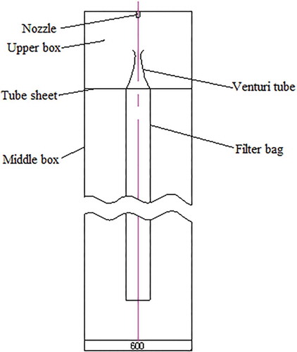
Since experimental validation is of the utmost importance, the geometry of the numerical model must closely resemble the experimental setup. Therefore, the specification and dimension of the bag are . A single bag is held in place by an internal middle box with a diameter of 600 mm as shown in . The height of an upper box and that of a middle box are 260 mm and 2600 mm, respectively. The inlet of an upper box and the outlet of a middle box are the opening state. The bags are simulated as a porous interface applied on the cell faces acting as a membrane allowing fluid to pass while experiencing a pressure loss defined by
Figure 4. Single bag cleaning geometric model.
where denotes are the pressure, and
is the resistance coefficient in Pa-s m−1. The flow across the filter is dominated by viscous forces due to the very low velocity
. The pressure drop across the filter is approximately 1000 Pa. According to eq 24, the permeability of the porous interface is 6 × 10⁻¹³ m2.
The relevant parameters of four working conditions selected by the numerical simulation and the subsequent experiment are shown in . Given the bag peak pressure of 2000–5000 Pa during cleaning, the equivalent increase in radial reverse flow speed is considered sufficiently low to still assume viscous dominance. Therefore, the bag peak pressure of 2500 and 4500 Pa is chosen as an expected value. Low-pressure filters operate at a tank pressure of 2–3 MPa; nevertheless, traditional high-pressure filters operate at much higher pressure, typically 4–7 MPa. Because the flow during pulse-jet cleaning is characterized as being both supersonic and subsonic, the pressures of 0.18 MPa and 0.2 MPa are chosen as the air pressure. Based on four working conditions, a venturi shaped rectifier tube is installed at the entrance of the filter bag. The corresponding venturi tube structure sizes under the four conditions are listed in .
Table 1. Four working conditions used in numerical simulation.
Table 2. Size of the venturi-type rectifier tube.
Due to the variation characteristic of air pressure in the purge tube in the process of the pulse valve being open and closed, the exit airflow is difficult to ensure, especially when air pressure in the purge tube is smaller than the critical pressure. Thus, numerical simulation is only carried out with exit airflow when the air pressure in the purge tube reaches the maximum value. The dynamic procedure of the pulse-jet cleaning process is predigested to study the procedure when the air pressure reaches the maximum value.
Boundary conditions and mesh
A pressure inlet with gas pressure is applied in the inlet of the nozzle model, and a pressure outlet with a total pressure equal to 0 Pa (relative to the reference pressure) is applied in the outlet of the nozzle model as the boundary condition. Further, the boundary condition of the single-bag model’s upper exit is to use the pressure inlet. The nozzle’s exit velocity, which is numerically simulated, is regarded as the single bag model’s nozzle entry velocity. The values of turbulence intensity at the inlet and outlet are set based on the hydraulic radius and Reynolds number.
The temperature of the compressed air at the nozzle and on the dust remover is 300 K. The gas inside the nozzle and in the jet airflow from the nozzle exit is regarded as compressed gas. However, the gas in the upper box and middle box is regarded as incompressible gas. The standard wall functions are selected as boundary conditions of the nozzle and all solid walls in the single bag model.
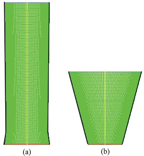
The mesh of a filter bag is established as shown in . The shapes of tapered and Laval nozzles are regular. A structured grid is adopted and appropriately compacted near the grid. The flow field in the jet and nozzle, including the near-field region, is found to be sensitive, due to the larger gradient present there. A more adaptive unstructured grid is adopted and compacted (see )., Further, a structured grid is adopted for the space inside and outside of the middle box and compacted at the bag opening and the space inside and outside of the filter bag.
Figure 5. The mesh of a single bag.
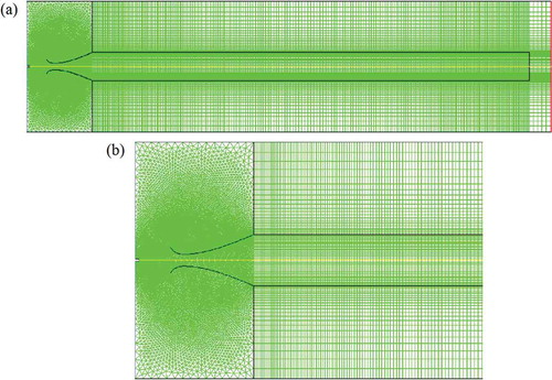
Figure 6. The mesh of the nozzle: (a) the mesh of Laval nozzle model; (b) the mesh of the tapered nozzle model.
Governing equation
While the airflow’s condition is simulated by using Fluent software for filtering and cleaning the bag, the gas inside the nozzle and in the airflow at the outlet is considered as compressible ideal gas; the gas in the upper box and inside and outside of the bag is considered as incompressible ideal gas. The gas flowing process followed the airflow’s mass conservation, momentum conservation, energy conservation, and κ-ε equation in the turbulent current state. In the κ-ε equation, the constants are as follows: empirical constant , empirical constant
, empirical constant
, turbulent kinetic energy κ corresponding to the Prandtl number
, and dissipation rating corresponding to the Prandtl number
; for compressible gases there are pulse expansion items
, in which
is gas density,
is turbulent dissipation rate,
is turbulent Mach number,
,
is turbulent kinetic energy, and
is the speed of sound.
Initial conditions
The computational domain needs to be initialized before solving the flow field. In the nozzle model, the computational domain is initialized by the boundary condition of the nozzle’s inlet. In the single bag model, the computational domain is initialized by applying a velocity of the nozzle’s outlet, which is the result of numerical simulation. A temperature of 300 K is applied throughout the domain.
Results and discussion of numerical simulation
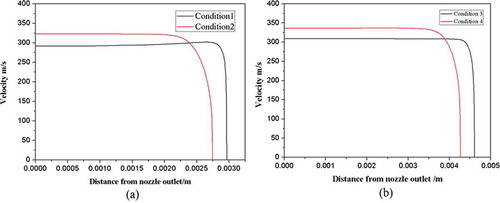
Simulated results show that when the pressure at the inlet of the nozzle is increased by 1%, the flow velocity at the nozzle exit is the same as the theoretical calculation value. This is because increasing pressure of compressed air can be used to compensate the resistance loss of airflow through the nozzle’s inner wall. The flow velocity at the nozzle exit as illustrated in is exported in the form of a profile, and this is used as an inlet condition at the nozzle of the single bag geometric model.
Figure 7. Distributions of jet airflow field in four working conditions.
On the basis of four working conditions, numerical results of the pulse pressure obtained within the bag and axial distribution of radial reverse flow speed are shown in and . As seen from the figure, the peak pressure in working conditions 1 and 2 reaches approximately 2100 Pa, which is 84% of the theoretical value. The peaking pressure in working conditions 3 and 4 reaches approximately 3700 Pa, which is 82% of the theoretical value. Moreover, the pulse pressure distribution obtained within the bag and axial distribution of radial wind velocity are relatively uniform. It should be noted that the pressure of the cleaning airflow in the bag is smaller than the target value. That is because the process of jet flow in the upper box is not an ideal free jet. Also, the accumulative effects of the local loss of pressure due to the process of jet flow into the filter bag through the rectifier tube influence the result. The pressure of the cleaning airflow in the filter bag is well distributed. That is because of the rectifier tube installed, which rapidly turns the energy of gas jet into the static pressure of cleaning airflow. It not only avoids forming the negative pressure region because of high speed of cleaning airflow in the upper exit of the filter bag, but also prevents resistance loss caused by high-speed cleaning airflow leading to lower static pressure of cleaning airflow at the bottom of the filter bag.
Figure 8. The bag axial pressure distribution in four conditions.
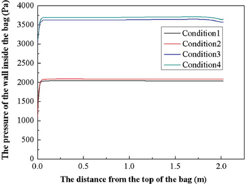
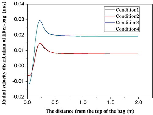
Figure 9. The distribution of radial reverse flow velocity in four conditions.
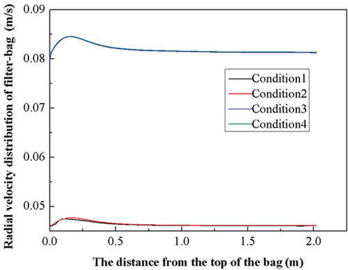
The diameter at the nozzle exit and the flow velocity should be appropriately modified to achieve the target of the peak pressure of cleaning system in the bag. Generally, increasing the nozzle diameter is used as a way to adjust the flow during the pulse-jet cleaning in engineering practice. The pulse pressure distribution obtained within the bag and axial distribution of radial wind speed after modifying the diameter of nozzle outlet are shown in and . gives the specific values of the diameter of the nozzle outlet after being corrected.
Table 3. The value of nozzle diameter before and after the modification in numerical simulation.
Figure 10. Axial pressure distribution in filter bag after the modification.
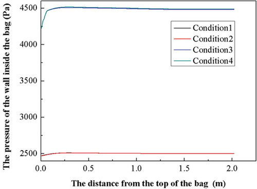
Figure 11. Radial velocity distribution of filter bag after the modification.
When the nozzle diameter is enlarged by approximately 1.13 times, the peak pressure of cleaning airflow in the bag could reach the target value (2500 Pa or 4500 Pa). In addition, the pressure of cleaning airflow in the bag and axial distribution of radial wind velocity are relatively uniform. After the diameter of the nozzle outlet is enlarged, although the flow velocity of nozzle outlet is not improved, the flow of the nozzle is increased to a considerable extent. The increase in the kinetic energy compensates various losses of pulse-jet airflow from the nozzle to the filter bag.
To validate the fact that the role of the venturi is to make the pulse travel easily into the bag, while restricting its escape and thereby increasing the pressure within the bag, the method of numerical simulation is used. This is mainly aimed at the working conditions such that the rectifier tube above the bag opening has been removed and the distance between the nozzle and bag opening has been adjusted to S (see eq 17). The results of numerical simulation are shown in –.
Figure 12. Axial pressure distribution in the filter bag without rectifier tube.
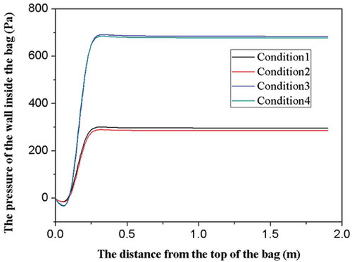
Figure 13. Radical velocity distribution of the filter bag without rectifier tube.
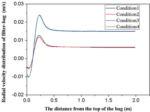
Figure 14. Axial pressure distribution in the filter bag after the modification without rectifier tube.
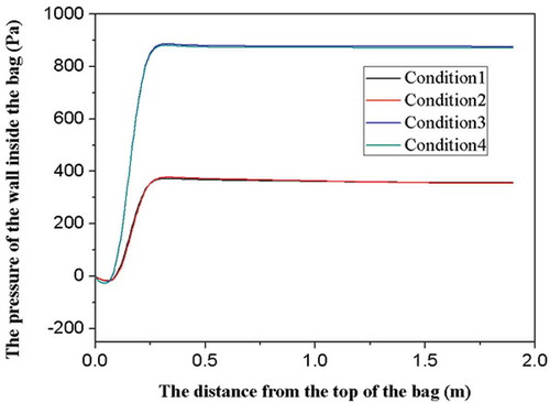
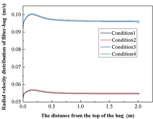
Figure 15. Radial velocity distribution of the filter bag after the modification without rectifier tube.
As shown in and , the pressure obtained within the bag is 300.189, 289.038, 691.006, and 684.296 Pa before the modification, respectively. The pressure after the modification has been improved 24–30%, but it still has a significant gap compared with the target value (2500 Pa or 4500 Pa). It can be seen from that the jet at the center location travels into the filter bag with rapid speed. However, the reverse airflow from the bottom of the bag to the top of it obviously exits at the edge region, and this causes the formation of a vortex ring with the airflow at the center location. Further, the formation of a vortex ring consumes a part of the kinetic energy of airflow at the center location; the airflow at the edge region cannot enter the bag due to its lower kinetic energy. The decrease in the mass flow causes the pulse pressure obtained within the bag to decrease.
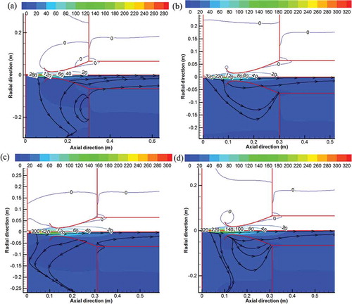
Figure 16. Velocity vector field from nozzle to the central portion of bag opening in four working conditions: (a) in working condition 1; (b) in working condition 2; (c) in working condition 3; (d) in working condition 4.
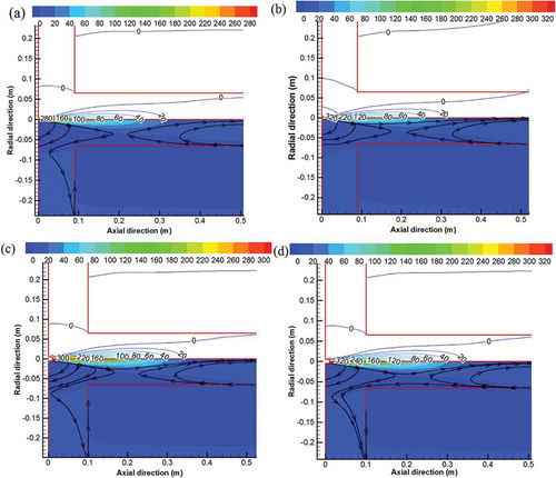
shows the velocity vector field between the pulse nozzle and the bag opening with rectifier tube in four working conditions after the diameter of the nozzle is modified. As seen in the picture, the pulse jet at the throat travels into the bag at a more uniform speed. Further, there does not exist an obvious vortex ring at the bag opening. This comparison of the velocity vector field and magnitude in two conditions confirms the result that the rectifier tube plays an important role in pulse-jet cleaning.
Figure 17. Distributions of jet airflow field from nozzle to the central portion of bag opening with rectifier tube in four working conditions: (a) in working condition 1; (b) in working condition 2; (c) in working condition 3; (d) in working condition 4.
Experimental measurement
Although the result of numerical simulation of the theoretical model is satisfying, the further research on cleaning performance of pulse-jet bag filters is also significant, especially for peak pressure of cleaning airflow. That is to say, the further research is helpful to complete comprehensive validation as an indispensable part of the theoretical model.
Experimental device and test methods
The composition of the experimental device is shown in . The specification of filter bag is mm, and the material of filter cloth is PPS needle felting, which is 500 g/m2. To keep the stability of filter and resistance characteristics of dust layer, the methods of brushing resin coating with pore-forming performance on the surface of filter bag is adopted. When the average wind velocity is 2 m/min, the pressure drop between the bag’s inside and outside is kept at 1500 Pa by adjusting the thickness of the coating. The pressure drop can be converted into the filter’s resistance coefficient, which is 45252 Pa-s m−1 (see Geometric model and working conditions section). The upper box and middle box of the single bag geometric model are made of polyvinyl chloride (PVC) pipe of
mm. Five groups of pressure sensors are installed on the surface of the filter bag along the axis. The model of the pressure sensor is E612 (country, France; range, 100 mbar; reaction time, 1 msec; voltage, 24 V) The locations of five pressure sensors in the system are 0.1 m, 0.5 m, 0.9 m, 1.4 m, and 1.8 m away from the bag opening. The right-angle solenoid valve DMF-Z-50S is used in the experiment (type, DN50; material, aluminum alloy; current, 0.8 A). In addition, the type of pressure sensor installed on the upper part of tghe nozzle is OA21 (country, Germany; range, 4 bar; reaction time, 1 msec; voltage, 24 V). Finally, the specification of storage is
mm, and the storage is equipped with pressure sensor type OA21. All pressure sensors are connected to the computer through a model UDAQ-20016 channel dynamic analyzer (country, China; standard USB interface; frequency, 200 Ksps; A/D resolution, 16 bit).
Figure 18. The experimental study of pulse-jet cleaning in fabric filters:
1, air compressor; 2, pulse air tank; 3, pulse valves; 4, nozzle; 5, venturi; 6, filter bags; 7, pressure sensor; 8, kinetic analyzer; 9, computor; 10, centrifugal fan; 11, filter housing; 12, air inlet; 13, air outlet; 14, dust collector.
The proper pressure valve for compressed air in the storage is selected to make the pulse pressure at the nozzle consistent with the setup pressure in the working conditions, according to the corresponding relationship of two pressure sensors’ values on the nozzle and storage in the process of tentative injection. In addition, the opening time of the valve is set to 0.1 sec. The measured values of five pressure sensors installed on the surface of filter bag are recorded by using a dynamic data acquisition system during pulse-jet cleaning.
Testing results and discussion
The pressure of cleaning airflow in the bag above the bag without rectifier tube
To test the effect of the peak pulse pressure in the process of pulse-jet cleaning, the nozzle diameter, pressure at the nozzle, and jet distance need to be determined according to the requirement of each working condition. As seen in , it is recorded that gas static pressure, which is respectively measured by five sensors located on the bags from top to bottom, changes with time in the five curves from curve 1 to curve 5. From the figure, the peak pressures of cleaning airflow at five locations are lower than the theoretical value. The peak pressure, which is recorded by using sensor 1 installed at the bag opening, is obviously lower than for the other sensors. As is discussed in the theoretical research, the diameter of the jet cross section is smaller than the diameter of the critical section at the bag opening. That means that the loss of the rectifier tube leads to the gas jet into the bag not being able to convert its own kinetic energy into static pressure in a timely fashion, and the air vortex formed below the bag consumes the energy of the gas jet substantially, which leads to the pressure of cleaning airflow in the bag being lower than the theoretical value. That is to say, the proportion of kinetic energy of cleaning airflow below the bag is larger, which leads to the gas static pressure being lower near the bag opening. It can be seen in and that cleaning time is longer, which may be ascribed to two reasons: that the switching time of pulse valve is difficult to control, and that the diameter is larger than that of the single bag and purge tube.
Figure 19. The pressure obtained within the bag as a function of time without rectifier tube, showing experimental results.
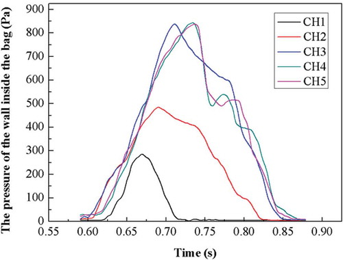
Figure 20. The pressure obtained within the bag as a function of time with rectifier tube, showing experimental results (the pressure sensor E612 is used; country, France; range, 100 mbar; reaction time, 1 msec; voltage, 24 V).
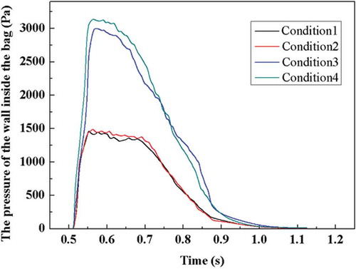
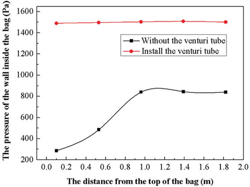
Figure 21. The comparison of axial distribution of pressure with venturi tube or without it.
The pressure of cleaning airflow in the bag and the bag with a rectifier tube
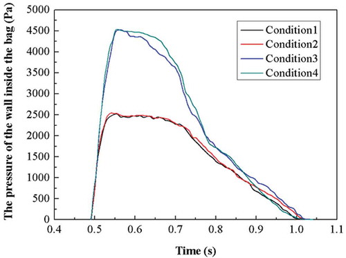
A venturi shaped rectifier tube designed by the theoretical model is installed above the bag, and the jet distance needs to be adjusted. The change of static pressure of cleaning airflow in the bag, which is measured by pressure sensor 3, is shown in . When the expected peak pressure of cleaning airflow in working conditions 1 and 2 is 2500 Pa, the peak pressure measured by pressure sensor 3 is approximately 1500 Pa. When the expected peak pressure of cleaning airflow in working conditions 3 and 4 is 4500 Pa, the measured peak pressure is approximately 3100 Pa. Furthermore, there is a gap between the measured peak value and the calculated target value of the theoretical model because of some negative factors discussed in the section on numerical simulation.
shows the axial distribution’s characteristics of the peak pressure of cleaning airflow obtained within the bag for the condition of whether the rectifier tube is installed, which aims at working condition 2. From the results of comparative analysis, it can be found that rectifier tube installed is not only helpful for improving the pressure of cleaning airflow, but also for the distribution of peak pressure along the axis. In addition, these two phenomena are ascribed to the following reason. Through the rectifier tube, the kinetic energy of the high-speed jet has been rapidly converted to the static pressure energy of cleaning airflow, and the intensity of vortex that the gas jet formed in the bag has been effectively reduced.
The pressure of cleaning airflow in the bag after modifying diameter at the bag opening
The peak pressure of the cleaning airflow in the bag is improved gradually by using the method of increasing the diameter of the nozzle’s outlet, under the premise of keeping the structure and operating parameters of other cleaning system. The test results show that when the diameter of the nozzle’s outlet can be adjusted to the value obtained by repeated experiments as shown in , the peak pressure can reach the expected value of theoretical model.
Table 4. The value of nozzle diameter before and after the modification in experiment.
On the location of pressure sensor 3, the change of cleaning airflow’s static pressure in the bag with time is as shown in .
Figure 22. The pressure obtained within the bag as a function of time with rectifier tube after the modification.
Conclusion
The matching relation between the flow of cleaning airflow injected into a filter bag and its own energy should follow Darcy’s law, according to the filter bag’s specifications and resistance properties, in order to achieve peak pressure of the cleaning airflow, which dominates the effects of the pulse-jet cleaning process in the bag. The peak pressure is regarded as a strength index of the pulse cleaning effect. A theoretical model of the pulse-jet cleaning system structure and operating parameters is established by using the theory of gas jet unitary adiabatic flow. The formation mechanism of pulse-jet cleaning effects of compressed air is expounded systematically. Scientific guidance is offered for the numerical simulation and experimental study of pulse-jet cleaning effects.
To examine the validity of the theoretical model, numerical simulation is carried out for the development process, in which the pulse-jet airflow flowed from nozzle to bag opening. It is also carried out for the conversion process, in which the jet flowing to the rectifier based on kinetic energy is converted into cleaning airflow in the bag based on the static pressure. Also, numerical simulation is carried out for the interaction process of cleaning airflow acting on a loaded dust filter cloth along the length of the filter bag. It is carried out on the basis of the cleaning system structure built by using the theoretical model and typical working conditions of operating parameters for two states: one such that the bag opening had no rectification measure installed, and one with a venturi-type rectifier tube installed above the bag opening. The numerical simulation shows that installing the rectifier above the bag opening of the filter bag can effectively convert jet flow near the bag opening to funnel flow at the throat of the rectifier. Although a gap existed between the peak pressure of cleaning airflow in the bag and the expected value calculated by using the theoretical model, the gap is not great. This confirms that the effects consume parts of the energy due to local resistance that the rectifier and the vortex produce at the connection area of the rectifier and bag opening, which leads to the flow of the effective cleaning airflow being reduced by analyzing the airflow field in the rectifier and bag opening.
The theoretical value of the nozzle’s diameter is enlarged by approximately 1.13 times, and the rectifier tube is installed at the bag opening again; the results of numerical simulation of the cleaning pulse-jet airflow flowing process indicate that the increases of airflow through the nozzle and average kinetic energy of the gas entering the entrance of the rectifier tube are caused by the expansion of the nozzle’s diameter. The increase in the kinetic energy is sufficient to compensate for the resistance losses of gas flowing through the rectifier and vortex area above the bag opening. The flow and static pressure of cleaning air entering the filter bag are fully able to reach the expected value of the theoretical model.
The result of an experimental device shows that the rectifier tube located above the bag opening has a great impact on increasing pressure of cleaning airflow in the bag. It has been confirmed that if nozzle diameter is enlarged by approximately 1.4 times compared to the theoretical diameter, the pressure of cleaning airflow in the bag can reach the expected value of the theoretical model.
In summary, the theoretical model has been verified through numerical simulation and experimental measurements, respectively. This shows that the theoretical model is suitable for optimising the pulse-jet cleaning system design in fabric filters.
Nomenclature
| = | flow of the cleaning airflow in the bag corresponding to the peak pressure, m3 s−1 | |
| = | diameter of filter bag, m | |
| = | length of filter bag, m | |
| = | peak pressure of cleaning airflow within the bag, Pa | |
| = | velocity peak of radical reverse flow speed of cleaning flow in the bag, m s−1 | |
| = | maximum velocity peak of reverse flow over the average value of flow velocity over the cleaning bag length, | |
| = | axis mean of radial reverse flow speed of cleaning airflow in the bag at the time of peak pressure formation, m s−1; | |
| = | permeability of the filter cloth and the dust layer, respectively, m2 | |
| = | thickness of the filter cloth and the dust layer, respectively, m | |
| = | is equivalent thickness of negative dust cloth, m | |
| = | dynamic coefficient of viscosity of cleaning airflow, Pa-s | |
| = | resistance coefficient of cloth and dust layer, Pa-s m−1; mainly depends on the filter bag dust load and resistance characteristics of dust layers | |
| = | jet angle D opening diameter of filter bag, m | |
| = | nozzle diameter, m S jet distance, m | |
| = | coefficient of experiment | |
| = | coefficient of turbulence, | |
| = | flow of nozzle outlet, m3 s−1; | |
| = | average kinetic energy of the critical section, Pa R radius of the jet critical section, m v velocity of the y point in the boundary layer of the same section, m s−1 | |
| = | axial velocity, m s−1 v0 flow velocity at the nozzle exit, m s−1 | |
| = | gas filtration velocity of filter bag | |
| = | density of the gas jet, kg m−3 | |
| = | adiabatic index (for air, k = 1.4) | |
| = | gas constant, J kg−1 K−1 | |
| = | gas temperature in stagnation state, K | |
| = | gas pressure in stagnation state, Pa | |
| = | gas pressure at the nozzle exit, Pa | |
| = | permeability of the filter cloth and the dust layer, m2 | |
| = | thickness of the filter cloth and the dust layer, m | |
| = | dynamic coefficient of viscosity of cleaning airflow, Pa s |
Funding
This study is financially supported by the National Natural Science Foundation of China (51078064).
Additional information
Funding
Notes on contributors
Jiying Cai
Jiying Cai is a graduate student in the College of Resources and Civil Engineering, Northeastern University, in Shenyang, People's Republic of China.
Wenge Hao
Wenge Hao is a professor in the College of Resources and Civil Engineering, Northeastern University, in Shenyang, People's Republic of China.
Cong Zhang
Cong Zhang is a graduate student in the College of Resources and Civil Engineering, Northeastern University, in Shenyang, People's Republic of China.
Jiaqi Yu
Jiaqi Yu is a graduate student in the College of Resources and Civil Engineering, Northeastern University, in Shenyang, People's Republic of China.
Ting Wang
Ting Wang is a graduate student in the College of Resources and Civil Engineering, Northeastern University, in Shenyang, People's Republic of China.
References
- Chen, C.J. 2001. Reducing pressure drop in a baghouse using flow distributors. J. Air Waste Manage. Assoc. 51(10):1471–5. doi: 10.1080/10473289.2001.10464364
- Choudhary, A.K., and A. Mukhopadhyay. 2013. Particulates: Selection of cleaning pulse pressure for pulse jet fabric filtration. Filtration Separation 50(4):20–30. doi: 10.1016/S0015-1882(13)70166-6
- Hemerka, O., P. Kosina, V. Adámek, and P. Hofmann. 2001. Contribution to improvement of pulse jet cleaning of industrial filters. J. Aerosol Sci. 32:847–80. doi: 10.1016/S0021-8502(01)00127-6
- Humphries, W., and J. Madden. 1983. Fabric filtration for coal-fired boilers: Dust dislodgement in pulse jet filters. Filtration Separation 20(1):40–4.
- Kanaoka, C., and T. Kishima. 1999. Observation of the process of dust accumulation on a rigid ceramic filter surface and the mechanism of cleaning dust from the filter surface. Adv. Powder Technol. 10(4):417–26. doi: 10.1163/156855299X00253
- Kurose, R., H. Makino, M. Hata, and C. Kanaoka. 2003. Numerical analysis of a flow passing through a ceramic candle filter on pulse jet cleaning. Adv. Powder Technol. 14(6):735–48. doi: 10.1163/15685520360732016
- Leubner, H., and U. Riebel. 2004. Pulse jet cleaning of textile and rigid filter media—Characteristic parameters. Chem. Eng. Technol. 27(6):652–61. doi: 10.1002/(ISSN)1521-4125
- Lo, L.-M., S.-C. Hu, D.-R. Chen, and D.Y.H. Pui. 2010. Numerical study of pleated fabric cartridges during pulse-jet cleaning. Powder Technol. 198:75–81. doi: 10.1016/j.powtec.2009.10.017
- Lu, H.-C., and C.-J. Tsai. 1999. Influence of design and operation parameters on bag-cleaning performance of pulse-jet baghouse. J. Environ. Eng. 125(6):583–91. doi: 10.1061/(ASCE)0733-9372(1999)125:6(583)
- Pham, M., C. Clark, and J. Mckenna. 2012. The evolution and impact of testing baghouse filter performance. J. Air Waste Manage. Assoc. 62(8):916–23. doi: 10.1080/10962247.2012.687360
- Piekaar, H. W., and L.A. Clarenburg. 1967. Aerosol filters—The tortuosity factors in fibrous filters. Chem. Eng. Sci. 22(12):1817–27. doi: 10.1016/0009-2509(67)80212-4
- Saleem, M., R.U. Khan, M.S. Tahir, and G. Krammer. 2011. Experimental study of cake formation on heat treated and membrane coated needle felts in a pilot scale pulse jet bag filter using optical in-situ cake height measurement. Powder Technol. 214(3):388–99. doi: 10.1016/j.powtec.2011.08.037
- Schiller, S., and H.-J. Schmid. 2015. Highly efficient filtration of ultrafine dust in baghouse filters using precoat materials. Powder Technol. 279:96–105. doi: 10.1016/j.powtec.2015.03.048
- Schildermans, I., J. Baeyens,and K. Smolders. 2004. Pulse jet cleaning of rigid filters: A literature review and introduction to process modelling. Filtration Separation 41(5):26–33. doi: 10.1016/S0015-1882(04)00234-4
- Sievert, J., and F. Löffler. 1989. Fabric cleaning in pulse-jet filters. Chem. Eng. Process. 26(2):179–83. doi: 10.1016/0255-2701(89)90010-X
- Tsai, C.-J.,and H.-C. Lu. 1998. Design and operation of a pilot-scale pulse-jet baghouse. J. Aerosol Sci. 29:S1079–80. doi: 10.1016/S0021-8502(98)90722-4
- Wilanowicz, J., W. Grabowski, M. Andrzejczak, and A. Chromiec. 2013. Assessment of the suitability of baghouse dusts from a dust extractor as fillers for hot-mix asphalt. Proc. Eng. 57:1269–77. doi: 10.1016/j.proeng.2013.04.160
- Yan, C., G, Liu, and H. Chen. 2013. Effect of induced airflow on the surface static pressure of pleated fabric filter cartridges during pulse jet cleaning. Powder Technol. 249:424–30. doi: 10.1016/j.powtec.2013.09.017
- Yang, Z. 2000. The effects on baghouse filter bags during the incineration of high-fluoride sites. Powder Technol. 108(2–3):160–3. doi: 10.1016/S0032-5910(99)00215-6