
ABSTRACT
The aim of this study was to examine the stress distributions with three different loads in two different geometric and threaded types of dental implants by finite element analysis. For this purpose, two different implant models, Nobel Replace and Nobel Active (Nobel Biocare, Zurich, Switzerland), which are currently used in clinical cases, were constructed by using ANSYS Workbench 12.1. The stress distributions on components of the implant system under three different static loadings were analysed for the two models. The maximum stress values that occurred in all components were observed in FIII (300 N). The maximum stress values occurred in FIII (300 N) when the Nobel Replace implant is used, whereas the lowest ones, in the case of FI (150 N) loading in the Nobel Active implant. In all models, the maximum tensions were observed to be in the neck region of the implants. Increasing the connection between the implant and the bone surface may allow more uniform distribution of the forces of the dental implant and may protect the bone around the implant. Thus, the implant could remain in the mouth for longer periods. Variable-thread tapered implants can increase the implant and bone contact.
Introduction
Osseointegration is a direct structural and functional connection between living bone tissues and a biocompatible titanium alloy surface without any fibrotic tissues. Dental implant-supported prosthesis have been widely used as a common treatment method to restore edentulousness in recent years.[Citation1] The main reason for implant loss after bone–implant connection is the loss of bone tissue which happens at the implant neck region. Peri-implant bone loss after occlusal loading arises from destructive forces along the long axis of the implant and/or a wrong loading direction. Load transfer from a titanium alloy dental implant to the surrounding bone tissues is believed to be one of the vital factors that determine the health of bone. Load transfer in dental implants is affected by the loading type, the material properties of the prosthesis and implant alloy, the geometric features of the implant, surface features and structure of the implant, the quality and quantity of the surrounding bone tissues and the natural features of the surrounding bone/implant interface.[Citation2–4]
Currently, there are many dental implant designs available for use.[Citation1–5] The level of loading induced in the bone due to occlusal forces has a vital effect for the maintenance of dental implants in function. Bone is maintained if the occlusal forces are distributed homogeneously. To avoid dental implant loss and produce a perfect implant system, it is vital to understand the biomechanics between the bone tissue and the dental implant.[Citation3] Finite element analysis (FEA) has been widely referenced in the dental implant technology to evaluate and analyse the stress distribution at the bone/implant interface for different dental implant designs, prosthetic designs and for different clinical options.[Citation1–6] Preferable dental implant system design should collect stress in areas remote to the marginal bone tissues. For this purpose, many studies have attempted to increase the contact area between the bone tissue and the dental implant and to reduce the crestal bone loss by reducing the stress on peri-implant bone.[Citation1–5] These studies, however, focus mainly on the implant size, geometry and length.[Citation1,Citation3–5,Citation7–9] In our previous study, we reported that implant length and diameter are the two key factors for stress distributions in implant systems. In our previous study,[Citation1] we reported that more stress accumulates in the peri-implant neck bone region in implants with a small diameter and short length, than in others. Hence, in our previous study, we suggested that the transmission of stress between the bone and the implant could be affected by the implant length and diameter.[Citation1] Based on length and diameter, dental implant-thread design has an important role in terms of the biomechanics of dental implants.[Citation7,Citation8] Therefore, this study, unlike our previous work, investigated the effect of implant-thread geometry on the stress distributions in two different threaded dental implant systems that have the same diameter and length.
Materials and methods
In this study, solid models of the implant and mandible were constructed using SolidWorks software and then transferred to ANSYS Workbench for FEA. The mandible was modelled in Solid Works using computed tomography, images shown in [Citation1]. The three-dimensional model of the mandible was as previously described in our previous study.[Citation1]
The Nobel Replace and Nobel Active (Nobel Biocare, Zurich, Switzerland) implants are used widely clinically and were modelled using the manufacturers’ data ().[Citation1] These implants were chosen because they are frequently used. The implants are both designed to be placed at bone level and both have the same length and diameter.[Citation1]
Figure 1. Implant models used in this study: Nobel Replace and Nobel Active (Nobel Biocare, Zurich, Switzerland).
The Nobel Active implant has variable-thread geometry. The grooves are designed to increase the bone contact with the body of the Nobel Active implant. The Nobel Active implant has a gradually expanding tapered implant body with a gradually increasing thread width. The implant has two reverse cutting flutes and sharp apical threads. The reverse-cutting action of the threads expands gradually. The coronal portion of the implant has a back taper.[Citation10] There is 1.2 mm between adjacent threads and 2.4 mm between contiguous threads. The threaded part in the neck region was 1.3 mm ().
Table 1. Quantitative characteristics of implants.
The Nobel Replace implant has a tapered implant body with reverse buttress grooves and uniform grooves over the entire implant. The thread steps and lengths are also uniform over the entire implant body. The thread is shorter than on the Nobel Active implant. The thread step is 0.71 mm and the threaded part of the neck region measures 1.5 mm ().[Citation11]
The constructed mandible models were divided into finite elements and boundary conditions and then a porcelain prosthesis, implant models, abutments, metal supports and an adhesive layer were mounted on the models.The mechanical features of the materials used were as previously described.[Citation1]
In this study, the implants were inserted in the region of the first molar. In order to define osseointegration between the implant surface and bone tissue, an area of inactive contact was defined between the implant and bone tissue.[Citation1,Citation4]
Three different loads were applied to the models to examine their effects on the tension distribution. In this study, the loads applied to the models were as in our previous study,[Citation1] where θ is the angle of the load in degrees and F is the magnitude of the load. When the applied load is vertical, FI = 150 N; when F at an angle of 15° to the vertical axis, FII = 200 N; and when F at an angle of 30° to the vertical axis, FIII = 300 N.[Citation1,Citation3,Citation5,Citation9,Citation12,Citation13]
Results and discussion
FEA is a powerful approach to analyse the stress and deformation occurring in the structure of geometrical models in implant technology. It is commonly used to determine the forces that affect the bone/implant interface or to evaluate different clinical and prosthetic options.[Citation1–5,Citation14]
In this study, FEA was used to examine the bone stress distributions in two different threaded commercial osseointegrated implants. All of the implants were implanted in the mandible in the first molar region. The stress distributions in the implant and surrounding bone tissues were evaluated on the basis of the von Misses stresses, similar to the approach employed in other previous studies.[Citation15,Citation16]
The greatest stress values were observed in the case of FIII loading for both implant types, while the lowest stresses occurred during FI loading in all loading conditions. The lowest stress was obtained with the Nobel Active implant at FI and the maximum stress, with the Nobel Replace implant at FIII.
The stress was greater in the cortical bone than in the cancellous bone and the stress increased with the diameter of the vertical load. For both dental implants, the stress in the bone decreased the larger the distance from the implant was. This shows that increasing the diameter of the vertical load increases the stress distributions for both implant types in bone tissues ().
Table 2. Stress distributions of peri-implant bone tissues.
The differences observed in the biomechanical behaviours in this study could be attributed to the fact that the implant systems were of different shapes, since the transmission of stress between the bone and the implant is thought to be affected by the implant geometry.[Citation17,Citation18] For example, some FEA studies of titanium implants show that the greatest stress intensity occurs in the implant neck region.[Citation1,Citation3,Citation9] This may be explained by uneven stress distribution in the bone socket and exposure of the bone tissue at the implant neck to the maximum stress.[Citation1,Citation3,Citation19] In our study, the stresses on the implants were concentrated in the neck region of the implant and the maximum von Misses stresses were within this region for both implant types. For both implants and all three load types, the greatest stress was in the cortical bone at the implant neck region (–).
Figure 2. Stress distributions in cortical and trabecular bone at FI load.
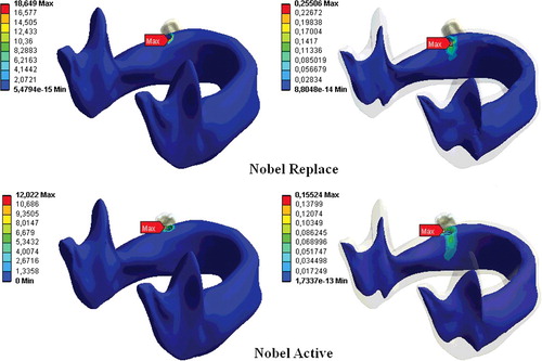
Figure 3. Stress distributions in cortical and trabecular bone at FII load.
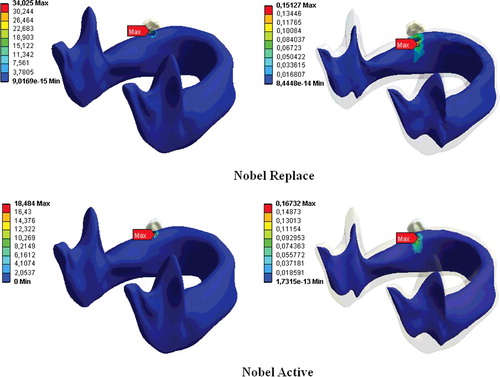
Figure 4. Stress distributions in cortical and trabecular bone at FIII load.
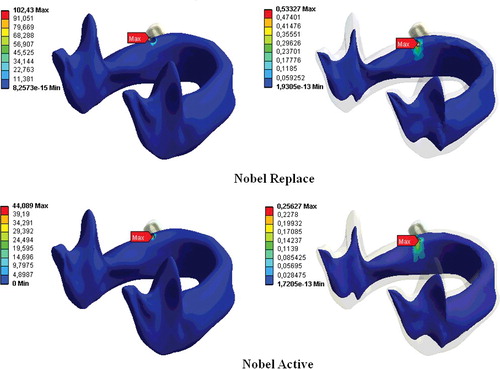
The bone loss that occurs in the implant neck region is an important factor in implant loss in the long run.[Citation7,Citation18] Reported three-dimensional FEA of dental implants indicate that oblique forces are more destructive than axial forces, and they cause greater stress accumulation in the peri-implant bone than do axial forces.[Citation20,Citation21] Our study clearly showed that an increase in the loading force at an angle to the vertical axis increased the stress distribution in both the implant systems (), which is in agreement with previous reports.[Citation1,Citation3,Citation18,Citation22]
For most single-molar implant-supported prostheses, bone loss occurs as a result of excessive occlusal loading.[Citation23] As the increased occlusal forces can cause implant losses by leading to crestal bone destruction, in addition to this, they can also cause abutment and implant loss by causing loosening of the abutment screw.[Citation24]
In our previous study,[Citation1] we showed that implant length and diameter are the important factors for stress distributions in implant system. In addition to this, thread design has an important role in terms of the biomechanics of dental implants.[Citation7,Citation8,Citation25–28] The different thread shapes include square, V-shape, buttress and reverse buttress threads, which are described using the thread thickness and angle.[Citation28] Threads are used in implant design to increase stability, increase the implant surface area and distribute the stress at the implant/bone interface.[Citation29,Citation30] The variables determining the functional surface area of an implant are the thread step, shape and depth.[Citation31] The smaller the thread step, i.e., the greater the number of threads, the greater the functional surface area of the implant keeping all other variables constant.[Citation31,Citation32] When other variables are fixed, the functional surface area increases with the depth of the implant threads.[Citation31] In a two-dimensional FEA, Chun et al. [Citation4] compared implants with V-shaped, square and reverse-buttress grooves. They found that square-thread implants were superior, especially in terms of the shear-shaped forces. An animal study compared three implant-thread forms with the same screw step and depth and measured the extraction torque that of the square-thread form was highest in three types of implants.[Citation8] Geng et al. [Citation16] reported that triangular and large square-thread implant forms could be used in cancellous bone, while thin-square-grooved implants should be avoided. Chang et al. [Citation33] examined the micro-movement of implants and peri-implant bone with different types of thread under immediate axial loading with 300 N, using FEA. They found that all micro-movement was located near the interface of cortical and trabecular bone and the square-thread profile was the best in terms of micro-movement. Other researchers have reported that implants with square threads best conduct stress, and data from FEA studies have demonstrated that the square thread has a more suitable stress distribution.[Citation8,Citation28,Citation31,Citation34] In this study, changes in implant geometry resulted in considerable differences in the stresses in the bone surrounding the implant (, –). In our study, in accordance with previous ones, the Nobel Active implant resulted in less stress accumulation with all loadings and this was thought to result from the surface-thread design, which had more threads, a larger groove diameter and a greater surface area than the Nobel Replace implant, resulting in more bone/implant contact.[Citation4,Citation9] Our results are in agreement with those of Arnhart et al. [Citation35] and Kielbassa et al. [Citation36] in clinical studies on Nobel Replace and Nobel Active implants. These two multi-centre clinical studies found that variable-thread tapered implants gave better clinical results for the peri-implant bone and soft tissues than standard implants.
Nevertheless, however powerful mathematical models may be, there are also some drawbacks: they cannot simulate oral tissues one-to-one and they can be used only to explain experimental results; their predictive power is used for comparisons.[Citation37–39]
Conclusions
Within the limitations of this study, dental implant geometry can be considered an important parameter to increase bone/implant connection. The increasing connection surface between the implant and bone tissue enables more homogeneous dispersion of forces acting on dental implants. Thus, it may help protection of the peri-implant bone tissue and may ensure a longer period of the implant in the mouth. Modified-thread tapered dental implants can increase bone/implant contact compared with tapered standard-thread implants. However, further studies are needed towards increasing the connection between the peri-implant bone tissue and the dental implant.
Acknowledgements
Serkan Dundar, Tolga Topkaya and Murat Yavuz Solmaz contributed equally to this work.
Disclosure statement
No potential conflict of interest was reported by the authors.
References
- Topkaya T, Solmaz MY, Dündar S, et al. Numerical analysis of the effect of implant geometry to stress distributions of three different commercial dental implant system. Cumhuriyet Dent J. 2015;18(1):17–44.
- Bozkaya D, Muftu S, Muftu A. Evaluation of load transfer characteristics of five different implants in compact bone at different load levels by finite elements analysis. J Prosthet Dent. 2004;92:523–530.
- Petrie CS, Williams JL. Comparative evaluation of implant designs: influence of diameter, length, and taper on strains in the alveolar crest. A three-dimensional finite-element analysis. Clin Oral Implants Res. 2005;16:486–494.
- Chun HJ, Cheong SY, Han JH, et al. Evaluation of design parameters of osseointegrated dental implants using finite element analysis. J Oral Rehabil. 2002;29:565–574.
- Tada S, Stegaroiu R, Kitamura E, et al. Influence of implant design and bone quality on stress/strain distribution in bone around implants: a 3-dimensional finite element analysis. Int J Oral Maxillofac Implants. 2003;18:357–368.
- Guven S, Atalay Y, Asutay F, et al. Comparison of the effects of different loading locations on stresses transferred to straight and angled implant-supported zirconia frameworks: a finite element method study. Biotechnol Biotechnol Equip. 2015; 29(4):766–772.
- Rieger MR, Mayberry M, Brose MO. Finite element analysis of six endosseous implants. J Prosthet Dent. 1990;63(6):671–676.
- Steigenga JT, al-Shammari KF, Nociti FH, et al. Dental implant design and its relationship to long-term implant success. Implant Dent. 2003;12(4):306–317.
- Geng JP, Tan KB, Liu GR. Application of finite element analysis in implant dentistry: a review of the literature. J Prosthet Dent. 2001;85:585–598.
- Orentlicher G, Teich M. Evolving implant design. The Nobel Active implant: discussion and case presentations. Compendium Continuing in Dentistry. 2010;31(1):67–77.
- NobelReplace® and Replace Select™ Tapered. Procedures manual [ Internet]. Zürich: Nobel Biocare Services AG; c2015 [cited 2015 Aug 6]. Available from: https://www.nobelbiocare.com/ca/en/home/products-and-solutions/library/manuals.html
- İplikçioğlu H, Akça K. Comperative evaluation of the effect of diameter, length and number of implants supporting three unit fixed partial protheses on stress distribution in the bone. J Dentistry. 2002;30:41–46.
- Chou I-C, Lee S-Y, Wu M-C, et al. Finite element modelling of implant designs and cortical bone thickness on stress distribution in maxillary type IV bone. Comput Methods Biomech Biomed Eng. 2014;17(5):516–526.
- Guven S, Eratilla V, Beydemir K, et al. The evaluation of stres distributions in 3 and 5 unit dental and implant supported fixed zirconia restorations: finite element analysis. Cumhuriyet Dent J. 2015;18(2):128–140.
- Teixeira ER, Sato Y, Akagawa Y, et al. A comparative evaluation of mandibular finite element models with different lengths and elements for implant biomechanics. J Oral Rehabil. 1998;25:299–303.
- Geng JP, Ma QS, Xu W, et al. Finite element analysis of four thread-form configurations in a stepped screw implant. J Oral Rehabil. 2004;31:233–239.
- Akpinar I, Demirel F, Parnas L, et al. A comparison of stress and strain distribution characteristics of two different rigid implant designs for distal-extension fixed prostheses. Quintessence Int. 1996;27:11–17.
- Holmgren EP, Seckinger RJ, Kilgren LM, et al. Evaluating parameters of osseointegrated dental implants using finite element analysis – a two-dimensional comparative study examining the effects of implant diameter, implant shape, and load direction. J Oral Implantol. 1998;24:80–88.
- Himmlova L, Dostalova T, Kacovsky A, et al. Influence of implant length and diameter on stress distribution: a finite element analysis. J Prosthet Dent. 2004;91:20–25.
- Papavasiliou G, Kamposiora P, Bayne SC, et al. Three-dimensional finite element analysis of stress-distribution around single tooth implants as a function of bony support, prosthesis type, and loading during function. J Prosthet Dent. 1996;76:633–640.
- Kitamura E, Stegaroiu R, Nomura S, et al. Influence of marginal bone resorption on stress around an implant – a three-dimensional finite element analysis. J Oral Rehabil. 2005;32:279–286.
- Van Staden RC, Guan H, Loo YC. Application of the finite element method in dental implant research. Comput Methods Biomech Biomed Eng. 2006;9:257–270.
- Rangert B, Krogh PH, Langer B, et al. Bending overload and implant fracture: a retrospective clinical analysis. Int J Oral Maxillofac Implants. 1995;10:326–334.
- Misch CE. Contemporaray implant dentistry. 3rd ed. St. Louis (MO): Mosby Elsevier; 2008. p. 337.
- Lee JH, Frias V, Lee KW, et al. Effect of implant size and shape on implant success rates: a literature review. J Prosthet Dent. 2005;94(4):377–381.
- Valen M. The relationship between endosteal implant design and function: maximum stress distribution with computer-formed, three dimensional Flexi-Cup blades. J Oral Implantol. 1983;11(1):49–71.
- Valen M, Locante WM. LaminOss immediate-load implants: I. Introducing osteocompression in dentistry. J Oral Implantol. 2000;6(3):177–184.
- Hyo-Sook R, Namgung C, Lee J-H, et al. The influence of thread geometry on implant osseointegration under immediate loading: a literature review. J Adv Prosthodont. 2014;6:547–554.
- Ivanoff CJ, Grondahl K, Sennerby L, et al. Influence of variations in implant diameters: a 3- to 5-year retrospective clinical report. Int J Oral Maxillofac Implants. 1999;14(2):173–180.
- Brunski JB. Biomechanical considerations in dental implant design. Int J Oral Implantol. 1988;5(1):31–44.
- Misch CE. Contemporaray implant dentistry. 3rd ed. St. Louis (MO): Mosby Elsevier; 2008. p. 810–811.
- Binon PP. Implants and components: entering the new millennium. Int J Oral Maxillofac Implants. 2000;15(1):76–94.
- Chang PK, Chen YC, Huang CC, et al. Distribution of micromotion in implants and alveolar bone with different thread profiles in immediate loading: a finite element study. Int J Oral Maxillofac Implants. 2012;27:96–101.
- Albrektsson T, Branemark PI, Hansson HA, et al. Osseointegrated titanium implants. Requirements for ensuring a long-lasting, direct bone-to-implant anchorage in man. Acta Orthopaedica. 1981;52(2):155–170.
- Arnhart C, Kielbassa AM, Martinez-de Fuentes R, et al. Comparison of variable-thread tapered implant designs to a standard tapered implant design after immediate loading. A 3-year multicentre randomised controlled trial. Eur J Oral Implantol. 2012;5:123–136.
- Kielbassa AM, Martinez-de Fuentes R, Goldstein M, et al. Randomized controlled trial comparing a variable-thread novel tapered and a standard tapered implant: interim one-year results. J Prosthet Dent. 2009;101(5):293–305.
- Adams MA. Spine update mechanical testing of the spine an appraisal of methodology, results, and conclusions. Spine. 1995;20(19):2151–2156.
- Arkın H, Xu LX, Holmes KR. Recent developments in modeling heat transfer in blood perfused tissues. Biomed Eng. 1994;41(2):97–107.
- Guven S, Aguloglu S, Beydemir K, et al. Examination of stress distribution and fracture resistance in five-unit tooth- and implant-supported partial fixed zirconia prosthesis. Biotechnol Biotechnol Equip. Forthcoming 2015. doi:10.1080/13102818.2015.1073122.