
ABSTRACT
Hardness mapping permits quantification of the properties of materials over microstructurally significant lengths. A technique has been developed whereby hardness maps can be generated to account for specific weld geometry and further refined using an adaptive approach. Once a preliminary map is produced, subsequent indents are placed in high hardness gradient locations to decrease interpolation distances between indentation sites. The method is demonstrated with three test cases: an Al-7010 friction stir weld, an Alloy 600/82 (NeT TG6) weld and an SA508–4N/Alloy 82/316LN dissimilar metal weld. The results show that the method has identified and resolved high regions with elevated hardness gradients. This provides the ability to resolve weld regions rapidly across large areas minimising indent counts.
Introduction
Indentation hardness analysis is a well-established technique employed to characterise the resistance of materials to plastic deformation via indenting the surface of a workpiece with an indentor of known geometry under a specific load and measuring the resultant geometrical footprint of the indent. The footprint is usually in the sub-millimetre range and therefore it is necessary to inspect the indent using optical magnification [Citation1,Citation2]. Indentation hardness is not considered a fundamental material property; it is a more arbitrary quantity that may be used to infer properties and to make material to material comparisons [Citation3]. It has been used to correlate with local yield strength [Citation4], tribological factors and local microstructural variations, both as bulk and local values. Many structural integrity codes make use of indentation hardness as one of the basic measurements for the cases, for example; ISO15156-1 [Citation5] and ASME BPVC Sec IX [Citation6]. Each test differs by the geometry and size of the indenter, but tests based on pyramidal indenters are the most prevalent since the same hardness scale can be used independent of the size of indent, applied load and material. Here, the focus is on the use of micro (<1 kg) and macro (>1 kg
) hardness measurements using the Vickers indenter geometry.
The hardness measurement provides a fast, reliable means to investigate mechanical properties, therefore allowing in-service structural integrity assessments to be undertaken in the absence of tensile test data [Citation7], such as weld integrity testing on pipe joints. However, this necessitates a relationship between hardness measurements and tensile properties. There are many theoretical analyses relating hardness to yield or flow stress [Citation8–10]. For example, Tabor [Citation4] devised an empirical formula, , describing a linear relation between Vickers hardness (HV) and yield strength
, with A being a material-specific constant.
For work-hardening materials, Tabor suggested that the yield strength should be replaced by the uni-axial flow stress (defined as the average of the yield and ultimate tensile stress) at a specified value of plastic strain [Citation7]. Others, such as Hart [Citation11] and Pargeter [Citation12] have developed approaches to utilise the hardness measurement as a technique for inferring flow properties within welded regions, including parent, heat-affected zone (HAZ) and weld metal (WM). These studies involved correlations between yield and hardness values in a variety of welding zones. Relationships with tensile strength have also been investigated by the same means of correlation [Citation13]. These types of empirical relations linking hardness and yield/ultimate tensile strength are used in relevant standards, such as ISO TC 164/SC4 and BS/ISO 7448. Recently, Hamelin et al. [Citation14] employed microhardness measurements to measure the post-weld phase distributions in weldments of SA508–3 ferritic steel. Cooper et al. [Citation15] investigated the extent of plasticity in the vicinity of notch roots in tested Charpy specimens of hot isostatically pressed (HIPed) and forged 304L stainless steel at ambient and C. Ghazanfari et al. [Citation16] used hardness mapping to investigate the mechanical properties of spot-welded AISI 4130 high-strength steel weldments, reinforcing that hardness mapping provides an effective method to provide insights into the mechanical behaviour of heterogeneous steel microstructure. Kavousi Sisi et al. [Citation17] investigated hardness variations in X52 micro-alloyed steel joints before and after post-weld heat treatment. Correlations in the results were then used to define empirical equations to link yield behaviour and grain-size to the hardness results observed. There are many other studies that describe where Vickers hardness has been used [Citation18–21] to infer local changes in material properties.
When performing hardness indents in close proximity to other indents, steps must be taken to ensure that the plastically affected zone around each indent does not overlap with neighbouring indents and hence influence the measured hardness value. Both BS EN ISO 6507-1 and ASTM E384-10 outline procedures that define the minimum spacing between indents and distance from the edge of the workpiece; typically 2.5–7 times the largest indent diagonal for a given loading rate (8–15 s). These standards are based on empirical data suggesting that the plastically affected zone associated with diamond pyramidal hardness measurements is essentially circular, being at minimum ranges of 1.25 times the indent diagonal for materials which do not present large amounts of plasticity/work hardening (the so-called ‘hard materials’) to 3.5 times for soft. Following this guidance, hardness maps can be generated which use multiple indents arranged in a coordinate pattern to reveal hardness distributions over a specimen. These maps can be then correlated with microstructural regions such as welding zones. However, the geometry of most hardness maps is generally basic and based on simple shapes, most commonly an array of points in a rectangular arrangement.
This paper presents an adaptive hardness mapping technique which is capable of
Evenly distributing an array of hardness measurement sites for non-rectangular regions of interest (ROIs) in an initial map.
Identifying sites with high hardness gradients either to reinforce a trend or eliminate spurious measurements in this initial map.
Iteratively performing further measurements in these regions while adhering to international standards regarding measurement placements and their proximity while updating the map.
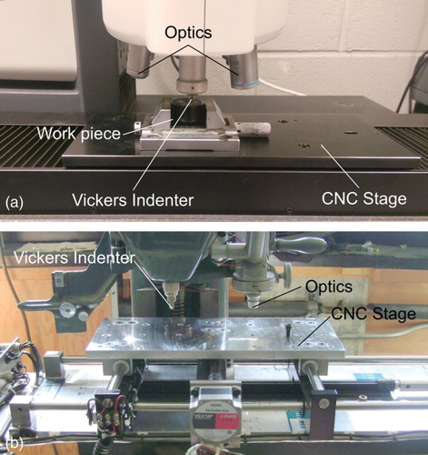
Adhering to ISO 6507-1 and ASTM E384-10, the method is applicable for any type of pyramidal indentation technique, material and domain. The article is structured as follows. First an overview of the method is presented, followed by three detailed hardness analyses performed on a friction stir weld (FSW), a similar metal weld (SMW, NeT TG6) and a dissimilar metal weld (DMW). These analyses, presented as hardness maps, highlight the methods functionality and applicability to different types of welds. This work has been completed using a Struers DuraScan 80 automatic hardness testing system shown in Figure employing customised computer code [Citation22]. While the method is best realised using a modern hardness tester with an addressable computer numerical control (CNC) stage, it can applied to a manual machine as long as indent locations can be controlled and tracked with accuracy.
Figure 1. Automatic hardness testing equipment: (a) automatic hardness testing machine (Struers DuraScan 80) used in the present work; (b) large-scale Vickers Hardness tester with CNC stage.
Method overview
The decision of how to distribute discrete hardness measurement points across a non-regular domain is non-trivial, which is why standard hardness mapping often considers only a rectangular array of measurement locations. This can lead to an imprecise balance between the number of measurements and their distribution relative to the local variations in hardness. As a result, the tracking of hardness variations over small microstructural distances can be rather coarse; a finer array of indents can be needed to accurately resolve steep gradients in local hardness properties. This is analogous to the issue faced by those practising finite element analysis (FEA), whereby the refinement of elements in areas of large gradients ensures sufficient resolution. In this case, adaptive meshing can be employed to ensure that an accurate solution is attained using the most computationally economical mesh. It is this ‘adaptive’ approach which has been applied to hardness mapping as described subsequently.
As using FEA terminology for the present application may be imprecise, measured hardness values will be referred to as indents, the predicted/anticipated locations of indents will be referred to as points, and the area available for indentation will be referred to as the ROI. An array of points generated at any iteration will be referred to as the mesh, with the usual meanings for ‘element’ and ‘seeding’ as used in FEA.
The technique consists in first acquiring the outline of the ROI to be mapped and subsequently indenting the workpiece in specific locations with reference indents which can later be identified as shown in Figure (a). These reference indents are usually performed at a different load and hence the variation in indent geometry is distinguishable from the mapping indents. These reference points not only allow removal of the workpiece between mapping iterations, but also provide reference values for hardness and indent size used in the generation of the initial mesh.
Figure 2. A simple example of workpiece set-up and refinement process. Light graphics indicate estimated indentation region, while dark show the actual measurement. (a) Example workpiece/ROI outline with reference indents prior (i) to meshing and after (ii). (b) Initial triangular array and estimated plastically affected zones (i), after first hardness assessment (ii), updated map (iii), subsequent map with overlap of plastic zones identified (iv).
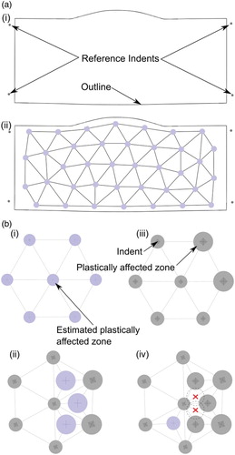
The ROI outline is then offset to move the seeding points away from the edge of the workpiece and points are spread around the new outline by the seeding parameters (either distance between points or by the number of points distributed around the outline) and a triangular mesh of indents is generated based on the Distmesh MATLAB code developed by Persson et al. [Citation23] The minimum distance between points is decided by a distance factor, 2.5–7 times the largest diagonal found in the array of reference indents, as per ISO 6507 or ASTM 384. If a hardness value significantly lower than that observed with reference indents is expected, then this factor versus the seeding parameter can be verified/adjusted accordingly.
Each element in the generated mesh is of a triangular shape as three points are needed to satisfy the Delaunay condition. The Distmesh code is used an iterative technique based on the analogy of a two-dimensional truss structure and Delaunay triangulation. It assumes a force–displacement function for the bars connecting points and solves towards equilibrium with an iterative, penalty-based technique. The result is that the ROI is populated with near-equilateral triangular elements conforming to the workpiece shape. This is particularly important as dissimilar triangle sizes would necessitate parsing the mesh to find potential sites where estimated plastically affected zones, calculated from known indent geometry would overlap, such as with the reference indents. If point locations do interfere with plastically affected zones, the offending points are removed, and the mesh is recalculated. At this particular stage in the analysis, the user can employ different seed spacings along with an uncertainty to ensure that plastically affected zones do not intersect in the initial mesh.
Initial mesh generation and the refinement process is shown schematically in Figure (a), where light colour indicates estimated plastically affected zone, grey indicates actual plastically affected zone from measured indents.
Once the initial hardness map has been performed as described, it may be iterated upon to find areas where the hardness gradient is the highest. This gradient is identified as the overall change in hardness over any given element. A programmed subroutine then verifies that an additional measurement can be placed on the centroid of this element based on the estimated plastically affected zone of the new points as shown in Figure (b). All experimental test cases presented have adhered to the relevant standards, where the plastically affected zone is assumed less than three times the average diagonal of the indent. The algorithm verifies that the estimated plastically affected zone of the new indent will not overlap with existing indents, using the largest indent in the element as the basis for estimation. If an overlap is found, this candidate site is then passed over and the next element is considered. The mesh is then updated with new points and triangular elements. Further hardness measurements then take place at each new point. This cycle repeats until either a pre-determined target hardness gradient is reached, i.e. the majority of new indentation sites appear in parent metal in the case of welds, or subsequent points cannot be placed due to overlap of estimated plastic zones. Therefore, beyond the initial map, the resolution of this method is not explicitly defined. Figure displays the typical work flow for initial hardness mesh generation using the Distmesh MATLAB code and subsequent refinement of results using additional point locations in high hardness gradient areas.
Figure 3. A flow diagram describing the initial mesh generation, indentation and further refinement of hardness maps from workpieces using the technique described.
This method necessitates a stage with numerical controlled stage installed for use with a hardness tester, or other means of tracking indent locations and geometry across a workpiece. All hardness maps presented in the current work were performed with a Struers/EmcoTest DuraScan 80 automated hardness tester.
Representative results
Dissimilar metal weld
The DMW was a mock-up pipe weld, joining Inconel Alloy 82-clad SA508–4N low-alloy steel to 316LN stainless steel via a filler of Inconel Alloy 82 WM. This workpiece was indented with 1937 indents, 1337 initial indents and 2 refinements of 300 indents each using a load of 1 kg. The macrograph of general microstructure and welding zones is shown in Figure , followed by the results provided at three levels of refinement in the analysis. This is compared to the results obtained by re-preparing the sample and generating a hardness map distributing 1937 points evenly with a rectangular, square distribution (RSD). Even though there are significantly more points employed in this latter case, the map appears to identify the same level of detail as the initial map comprises 1337 indents.
Figure 4. DMW macrograph and hardness maps. Manufactured from Alloy 82 Clad SA508–4N low-alloy steel to 316LN Stainless Steel via a filler of Alloy 82. This workpiece was indented with 1937 indents; 1337 initial indents and 2 refinements of 300 indents each using a load of 1 kg. Showing the first (top), second and third maps (middle), black dots show indent locations. Also shown is a map generated without refinement, approximating an RSD comprising 1937 indents (bottom).
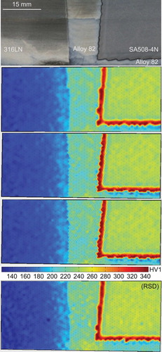
The subject weld contains a variety of complex microstructures due to the differences in compositions of the parent metals, heat treatments and thermal cycling from the welding and cladding processes, shown in Figure . The highest hardened areas are apparent within the DMW adjacent to the interface between the WM and the SA508–4N in both the weld and clad areas as a result of the heat flux and thermal cycling during the weld process altering the local response to plastic deformation. Hardening can also be seen in the 316LN stainless steel adjacent to the WM interface; however, the affected area is much deeper into the parent metal. There is significant variation within the WM globally as a result of grain orientation, but locally due to microstructural features such as hard semi-metallic inclusions and carbide formation.
The iterative hardness mapping technique was able to provide a refined result along the main boundary zones. For example, some depletion and softening of the SA508–4N at the Alloy 82 interface is not observable on the first iteration, and can be readily observed in subsequent iterations.
NeT TG6 Inconel similar metal weld
The SMW (NeT-TG6 [Citation24]) was fabricated from 12-mm thick Alloy 600 plate containing three superimposed Alloy 82 weld passes deposited via a tungsten inert gas (TIG) process. This specimen was indented with 928 indents (253 initial indents and 9 subsequent indents of 75 indents each) using a load of 0.5 kg. The macrograph of general microstructure and welding zones is shown in Figure .
Figure 5. NeT TG6 SMW macrograph and hardness maps. This cross-section was extracted from 12-mm thick Alloy 600 plate containing three superimposed Alloy 82 weld passes deposited via a TIG process. Map shows a total 928 indents (253 initial indents and 9 refinements of 75 indents each) using a load of 0.5 kg. The first, fifth and ninth maps are shown, black dots indicate indent locations. Subplots on the right show line scans comprising indents between the lines shown on the left, with symbols showing indents, and lines showing an interpolated spline.
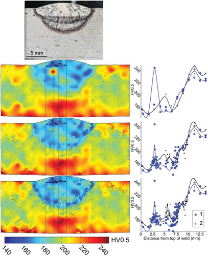
The NeT TG6 similar weldment was monitored with thermocouple arrays on both top and bottom surfaces during welding which revealed the high heat input generated a peak temperature that exceeded 900C on the bottom face directly beneath the weld bead. The workpiece used for hardness mapping was sectioned at weld mid-length to reveal the fusion boundaries within the NeT-TG6 SMW. The material combination proved to result in an under-matched weld as the WM and HAZ are significantly softer than the parent metal (plate). There is also evidence of cyclic hardening in the parent metal beneath the weld and to lesser extent in the WM and a thin zone near the surface of the plate. The latter is most likely a result of the plate forming process as both the upper and lower surfaces of the plate were left un-machined before welding.
The technique was able to determine the extent of the HAZ within ∼80 µm, as well as the condition of the parent material well outside the weld region. Two line scans have been imposed on the acquired hardness maps, centred on the peak hardness locations to demonstrate the competition between refinement of gradient levels. The first one, line scan 1 in Figure , was centred on an inclusion site an inclusion which was identified by subsequent refinement. The second one, line scan 2, passed through a region of relatively high hardness, but the overall gradient, i.e. how fast the hardness changed in that area, was relatively low and did not receive additional measurement sites as the HAZ featured more prominent areas. These two line scans demonstrate that subsequent measurements were placed in regions where the local hardness was highest.
Aluminium friction stir weld (FSW)
Autogenous, stationary shoulder friction stir welding (FSW) was used to join 6-mm thick rolled plates of AA7010–T7651 aluminium alloy. The procedure utilised a pin rotation speed of 1500 rev min−1 and a travel speed of 200 mm min−1. This specimen was then sectioned and polished, followed by hardness mapping involving 1436 indents (236 initial indents and 8 subsequent refinements of 150 indents each) using a load of 0.5 kg. A macrograph showing the general microstructure and welding zones is shown in Figure .
Figure 6. Aluminium FSW macrograph and hardness maps. A 6-mm thick AA7010-T7651 aluminium alloy workpiece was processed via autogenous FSW with a pin rotation speed of 1500 rev min−1 and a travel speed of 200 mm−1. This workpiece was indented with 1436 indents (236 initial indents and 8 refinements of 150 indents each) using a load of 0.5 kg. The first, third, fifth, seventh and ninth levels of refinement are shown. Black dots show indent locations.
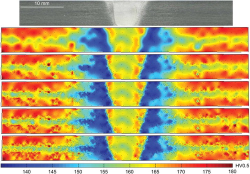
The hardness results show that the parent material has a hardness of 170–175 HV near the surfaces and a slightly lower value in the middle of the plate. This difference may be induced by the non-uniform in thickness quenching and rolling effects (rolling bands) during the production of the aluminium plates [Citation25]. It can be seen that there is a drop in the hardness from the parent metal towards the HAZ and a recovering trend in the weld nugget (WN). This type of hardness distribution is related to the precipitate evolution in AA7010 as a response to the thermal cycle during the welding process. It is believed that for heat treatable aluminium alloys, a drop in hardness in the HAZ is due to coarsening of precipitates. In the WN, the peak temperature exceeds the solvus of the strengthening phase, bringing strengthening precipitates back into solution and leading to strength recovery following periods of natural ageing [Citation26].
The iterative hardness mapping procedure employed was able to very clearly identify the various weld zones, but also the extent of the rolling bands in the parent material and their interaction with the weld region.
Discussion
Each test case (FSW, SMW and DMW) shows that the majority of indents are placed around weld areas, accurately refining the areas of highest gradient. As these areas of interest become populated, the highest gradient left for investigation becomes lower until the gradients observed are due to microstructural features within parent metals. As the main areas of interest had been sufficiently indented, no further addition indents were added in the test cases. This can also be achieved by setting a target hardness gradient based on the hardness values expected within the parent metals used in the weldment.
The process of indenting and refining a hardness map via the refinement method has provided a time-effective technique for increasing density of data in areas of high hardness gradient. In all test cases, the results have shown that the method accurately tracks the point locations, estimates the plastically affected zones and the orientation of workpiece. This was conducted while deriving new points with knowledge derived from implemented indentations in areas with high hardness gradients, thus the method updates on each iteration with actual indent-specific location, specific geometry and plastically affected zone size. As greater loads and softer material will create larger indents for a given material or given load, the resolution limit is therefore inherently tied to the variables used in the test and the specimen material, i.e. a larger indent will produce a lower resolution limit. Therefore, it is imperative, much like in a ‘normal’ hardness map, to know the expected lower bound hardness measurement for the initial map. If a higher resolution is required at the highest indent density possible, then the machine operator must use a lower load to increase the resolution limit.
In all three test cases, the method has accurately placed more indents in the locations where the highest gradients are situated and throughout various iterations, has found weld boundaries and refined them alongside weld zones. This shows that there is potential for disambiguation between a variety of welding zones within the HAZ (coarse grained, fine grained) as the technique would refine the mesh around the borders of these zones. This would take refinement of the hardness measurements in the regions along with correlation with microstructural observations, material history and empirical data. This method could compliment other techniques [Citation14,Citation16,Citation17] where microstructural analysis has taken place and gradients are expected over workpieces. The present work has focused on using metal welds to display the technique but it is not limited to this. This method could be used for refining measurements over various other workpieces where there is rapid changes in hardness, such as microstructural features, grain boundaries, inclusions, phase distributions and plastically affect zones [Citation15]. Further refinement is possible via indenting with a lower load, creating smaller plastically affected zone and increasing indentation density.
The implications of not refining are significant when iterations are compared. As indents are added in high-gradient areas, macro-level (weld beads, welding zones) and microstructural features can be identified, and in areas of high-indent density distances can be inferred, thus reducing error in final measurements. As a result of these additional indents, the map plotting tools interpolate over shorter lengths and display a more reliable representation of the local response to plastic deformation. This is shown in the SMW (Figure , NeT TG6 SMW) where one point within the WM is refined throughout the process. After the first iteration, there is a high hardness area, but after subsequent iterations, this area is refined and is shown to be a small area.
Within this body of work, the Distmesh code has been applied to the hardness measurement, but it is not restricted to this. The most obvious future application is nano-indentation mapping as this is another point-based indentation technique. In reality, this technique could be implemented wherever a point array is used as an investigation tool.
Summary
A new method for hardness mapping has been developed where hardness gradients are actively tracked by adding further indents to an initial hardness map and thus increasing data density in a time conservative manner. The method tracks hardness values and indent locations such that new indents can be placed within an already tested array of indents with high accuracy. The technique has been realised on a friction stir weld, a similar metal weld and a DMW. The main points of this work are as follows:
The hardness mapping method can be applied to any shape and size of workpiece within limits of sample preparation and tester.
The technique actively tracks local hardness gradients, updating the hardness map with additional indents in areas of high hardness gradient where possible according to the plastically affected zones.
Three test cases (autogenous friction stir weld, similar metal weld and DMW) have been mapped and refined using the technique and results shown. All three test cases validate the method showing that hardness gradients are actively tracked and weld ROIs are refined well.
Acknowledgements
W. J. Brayshaw and M. J. Roy acknowledge the financial support from the EPSRC (EP/L01680X/1) through the Materials for Demanding Environments Centre for Doctoral Training. The authors also acknowledge the contribution made by the members of NeT Task Group 6 and Amec Foster Wheeler, Warrington, UK.
Disclosure statement
No potential conflict of interest was reported by the authors.
Related Research Data
References
- Maier A, Uhl A. Areamap and Gabor filter based Vickers hardness indentation measurement. European Signal Processing Conference; 2013. p. 1–5. ISSN 22195491
- Maier A, Uhl A. Robust automatic indentation localisation and size approximation for vickers microindentation hardness indentations. 7th International Symposium on Image and Signal Processing and Analysis (ISPA 2011); 2011. p. 295–300.
- Meyers MA, Chawla KK. Mechanical behavior of materials; 2009. ISBN 9780521866750
- Tabor D. A simple theory of static and dynamic hardness; 1948. ISSN 1364–5021
- NACE. Petroleum and natural gas industries Materials for use in H2S-containing environments in oil and gas production. Part 1: General principles for selection of cracking-resistant materials. ANSI/NACE MR0175/ISO 15156-1; 2009.
- ASME. 2010 ASME boiler & pressure vessel code: IX qualification standard for welding and brazing procedures, welders, brazers, and welding and brazing operators; 2011.
- Zhang P, Li SX, Zhang ZF. General relationship between strength and hardness. Mater Sci Eng A. 2011;529(1):62–73. ISSN 09215093 doi: 10.1016/j.msea.2011.08.061
- Bishop RF, Hill R, Mott NF. The theory of indentation and hardness tests. Proc Phys Soc. 1945;57(3):147–159. ISSN 0959-5309 doi: 10.1088/0959-5309/57/3/301
- Cheng Y-T, Cheng C-M. Scaling, dimensional analysis, and indentation measurements. Mater Sci Eng R: Rep. 2004;44(4–5):91–149. ISSN 0927796X doi: 10.1016/j.mser.2004.05.001
- Johnson KL. The correlation of indentation experiments. J Mech Phys Solids. 1970;18(2):115–126. ISSN 002250963 doi: 10.1016/0022-5096(70)90029-3
- Hart PHM. Yield strength from hardness data. The Welding Institute Research Bulletin; 1975. p. 176.
- Pargeter RJ. Yield strength from hardness – a reappraisal for weld metal. The Welding Institute Research Bulletin; 1978. p. 325–326.
- Pavlina EJ, Van Tyne CJ. Correlation of yield strength and tensile strength with hardness for steels. J Mater Eng Perform. 2008;17(6):888–893. ISSN 10599495 doi: 10.1007/s11665-008-9225-5
- Hamelin CJ, Muránsky O, Smith MC, et al. Validation of a numerical model used to predict phase distribution and residual stress in ferritic steel weldments. Acta Mater. 2014;75:1–19. ISSN 13596454 doi: 10.1016/j.actamat.2014.04.045
- Cooper AJ, Cooper NI, Bell A, et al. A microstructural study on the observed differences in Charpy impact behavior between hot isostatically pressed and forged 304L and 316L austenitic stainless steel. Metall Mater Trans A. 2015;46(11):5126–5138. ISSN 1073-5623 doi: 10.1007/s11661-015-3140-9
- Ghazanfari H, Naderi M. Influence of welding parameters on microstructure and mechanical performance of resistance spot welded high strength steels. Acta Metall Sin (English Lett). 2013;26(5):635–640. ISSN 10067191 doi: 10.1007/s40195-013-0076-1
- Kavousi Sisi A, Mirsalehi SE. Prediction of microstructure and mechanical properties of line pipe welded joints based on hardness map. Sci Technol Welding Joining. 2015;21(1):43–52. ISSN 1362-1718 doi: 10.1179/1362171815Y.0000000064
- Moon DW, Lambrakos SG, Wong RJ, et al. Temperature, macrostructure and hardness in high strength low alloy steel welds. Sci Technol Welding Joining. 2003;8(5):334–339. ISSN 1362-1718 doi: 10.1179/136217103225005561
- Moon DW, Lambrakos SG, Wong RJ, et al. Macrostructure, hardness, and temperature in HSLA100 steel weld. Sci Technol Welding Joining. 2003;8(2):95–101. ISSN 1362-1718 doi: 10.1179/136217103225010880
- Qiao D, Zhang W, Pan T-Y, et al. Evaluation of residual plastic strain distribution in dissimilar metal weld by hardness mapping. Sci Technol Welding Joining. 2013;18(7):624–630. ISSN 1362-1718 doi: 10.1179/1362171813Y.0000000144
- Metzbower EA, Denney PE, Moon DW, et al. Thermal analysis and microhardness mapping in hybrid laser welds in a structural steel. Mater Sci Forum. 2003;426–432:4147–4152. ISSN 1662-9752 doi: 10.4028/www.scientific.net/MSF.426-432.4147
- Roy MJ. HardnessMap, June 2016. Available from: http://dx.doi.org/10.5281/zenodo.54761
- Persson P-O, Strang G. A simple mesh generator in MATLAB. SIAM Rev. 2004;46(2):329–345. doi: 10.1137/S0036144503429121
- Smith MC, Smith AC, Wimpory R, et al. A review of the NeT task group 1 residual stress measurement and analysis round robin on a single weld bead-on-plate specimen. Int J Press Vessels Piping. 2014;120–121(1):93–140. ISSN 03080161 doi: 10.1016/j.ijpvp.2014.05.002
- Altenkirch J. Stress engineering of friction stir welding: measurement and control of welding residual stresses [PhD Thesis]. Manchester: University of Manchester; 2009.
- Threadgill PL, Leonard AJ, Shercliff HR, et al. Friction stir welding of aluminium alloys. Int Mater Rev. 2009;54(2):49–93. ISSN 0950-6608 doi: 10.1179/174328009X411136