Abstract
It is difficult to obtain the dynamic temperature field and the variation pattern with the experimental method as the temperature field changes very fast in the laser sintering process. In this study, a mathematical model for the dynamic temperature field was established during selective laser sintering (SLS) with nano-hydroxyapatite (HAP) ceramic powder. The dynamic loading of a moving laser heat source with a Gaussian distribution was realized with ANSYS Parameter Design Language. The variation pattern of a three-dimensional transient temperature field at different speeds of the moving laser heat source was analysed as the change of thermal physical parameters with temperature was taken into account in the developed model. The results show that the maximum temperature point on the sintered layer surface is slightly lagged from the laser spot centre with the moving laser heat source when the offset distance is 0.4 mm, laser power is 10 W, laser spot diameter is 2 mm and laser speed is 200 mm/min. The temperature decreases rapidly with the increase of sintering depth. The temperature field that the characteristic microstructure of the sintered parts represents coincides with that by the analysis with finite element calculation. This study may provide useful guidance for selecting the reasonable processing parameters during SLS.
1. Introduction
Selective laser sintering (SLS) is a solid freeform fabrication technique [Citation1]. It consists of building a three-dimensional (3D) object layer by layer selectively sintering or partial melting a powder by laser radiation [Citation2]. The technology can sinter powder materials into dense parts directly and mold is not required in this process. The research on SLS has become a hot topic at present due to itsadvantages of short manufacturing cycle [Citation3], wide range of materials [Citation4] and so on. Temperature is the most important factor that affects sintering quality in the process of SLS [Citation5]. The dynamic temperature field changes very fast in the laser sintering process. In fact, temperature field is influenced by many factors, especially the thermal physical parameters that change with temperature. So, it is difficult to obtain the dynamic temperature field and its change rule in the laser sintering process with the experimental method [Citation6].
With the development of computer technology and finite element theory, it has become a reasonable way to study the laser sintering temperature field with finite element method (FEM) [Citation6]. The previous researches mainly focus on the dynamic temperature field of metal materials or polymer material in the laser sintering process. Matsumoto et al. [Citation7] have proposed a method for simulating the forming process of a single metallic layer on the powder bed in SLS. The distribution of temperature within the solid layer is calculated with the heat conduction and the elastic FEMs. Ren et al. [Citation8] have set up a 3D transient finite element model of SLS on the two-component metal powder W/Ni. The loading of the laser heat source with Gaussian distribution and the changes of thermal physical parameters with temperature are taken into account in their model. The interrelation between the temperature field and the processing parameters had been analysed. Dong et al. [Citation9] have developed a 3D transient finite element model of polymer powder.While there is little research on the dynamic temperature field of ceramic powder in the laser sintering process, especially on nano-ceramic materials, the parameters that can increase the product qualities and decrease the cost of production of SLS were analysed.
In this study, a finite element model has been developed to simulate the dynamic temperature field for the laser sintering of nano-hydroxyapatite (HAP) powder. The movement of the laser heat source with Gaussian distribution and the changes of thermal physical parameters with temperature were taken into account in this model. Numerical simulation of the temperature distribution and the changing rule of temperature field have been carried out in the SLS process. At the same time, the test and analysis of the sintered parts are studied with scanning electron microscopy (SEM) and X-ray diffraction (XRD).
2. Model establishment
2.1. Constitutive equation
The heat input and heat conduction have an important influence on the structure and property of sintering material in the laser sintering process. Sintering is a process of heating the local powder to high temperature, and then cooling rapidly. The sintering temperature changes rapidly with time and space, and the physical parameters also dramatically change with temperature due to a moving laser heat source. Therefore, the sintering temperature field analysis belongs to a typical transient heat conduction problem. Its constitutive equation of 3D heat conduction can be expressed as follows:
The coefficients of thermal conductivity, density and specific heat capacity of nano-HAP powder change with temperature in the laser sintering process. The physical parameters are shown in The coefficients of thermal conductivity and specific heat capacity of nano-HAP powder were reported when temperature varies from 20°C to 500°C [Citation10]. The thermal physical parameters of nano-HAP powder were reported when temperature is equal to 1300°C [Citation11]. The density of nano-HAP powder was also reported [Citation12].
Table 1. Thermal physical parameters of nano-HAP powder at different temperatures
The process of shrinkage and densification occurs in the laser sintering process. However, the effect of shrinkage on the temperature field is confirmed to be negligible [Citation9,Citation13]. The effect of shrinkage on the temperature field was considered by Chang and Tsai [Citation13]. Their results indicated a negligible influence of shrinkage on temperature histories. The shrinkage of the powder piles on the temperature field was also neglected during the finite element analysis of the temperature field in the SLS process [Citation9].
Significant radiation heat losses would occur at temperature above 1000 K. The laser spot radius used in our experiments is 1 mm. Vasudevan Raghavan et al. Citation[14] reported that the effect of radiation heat loss is usually assumed to be negligible for the small droplet sizes (about <1.0 mm). The effect of radiation heat loss cannot be neglected when the size is 3–5 mm, and it will experience an excessive radiation heat loss at very large size (>6.0 mm) [Citation14]. Shunhong Liu et al. [Citation15] studied the temperature field of laser bending of sheet metal. The heat losses due to radiation are ignored even at temperatures of 1600°C (above 1000 K). Therefore, the radiation heat losses are neglected in our simulation at temperatures above 1000 K due to the small size (laser spot radius is 1 mm).
2.2. Finite element model
The 3D finite element model of the SLS is shown in The selected model dimension is 20 mm × 4 mm × 2 mm. A fine mesh has been carried out with Solid 70, which is a 3D eight-node hexahedral element in ANSYS element library to improve the calculating accuracy. The surface element ‘Surf 152’ was used to cover the surface of powder layer for the loading of heat convection and heat flux at the same time. The mesh grid size is 0.2 mm and the time of a load step on the element is 0.05 s. The number of nodes is 23,331 and the number of elements is 26,400.
2.3. Heat source model
In the process of laser sintering, laser energy enters the powder in the form of heat flux, which obeys the Gaussian distribution [Citation16]. It is assumed that the absorption rate of powder materials to laser is αR. The heat flux q(x, y) of Gaussian distribution heat source can be expressed as follows [Citation17]:
2.4. Initial conditions and boundary conditions
The schematic of the laser sintering process is shown in The laser spot lies at the left of this model (x 0 = 0 mm, y 0 = 2 mm, z 0 = 2 mm) at the beginning of sintering. When the laser spot moves at a constant speed v (mm/min) along the x-axis, the location (L) of the laser spot on the upper surface of powder layer can be expressed as L = vt − x 0, where t is the scanning time of the laser spot. The location of the laser spot centre on the upper surface of powder layer is L 1 after t 1. There is a circular region with centre L 1 and radius r 0; the heat flux can be loaded on this circular region, which can be expressed as follows:
The location of the laser spot centre is L
2 on the upper surface of powder layer when time reaches t
2 (t
2 = t
1 + Δt) after an interval of time Δt. There is a circular region with centre L
2 and radius r
0. The heat flux can be loaded on this circular region as given in Equation Equation(3)(3), and the movement of laser heat source can be achieved on the surface of powder layer with this method.
An adiabatic boundary condition is applied to the lower surface during the laser sintering process, that is, . Convection condition is loaded on the upper surface and the profile of the powder bed, that is,
, where h is the convection coefficient of air. The initial temperature and the ambient temperature of the powder layer are 20°C in this simulation. The convection coefficient of air is 20 W/m2 °C.
3. Results and discussion
The temperature field was studied at different laser scanning speeds during the laser sintering when the other parameters remain unchanged. In other words, the other parameters that remained unchanged are as follows: laser power, 10 W; the spot diameter, 2 mm; the absorption rate of nano-HAP powder to laser, 0.87; and the initial temperature, 20°C. The laser scans from one end to the other end along a straight line on the surface of powder layer.
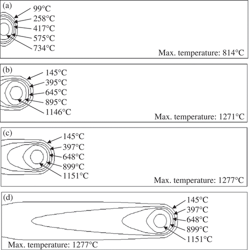
The temperature fields at different sintering times were analysed when the laser scanning speed is 200 mm/min. Isotherms on the upper surface of the sintered layer are shown in when the sintering times are 0.1 s, 0.5 s, 1 s and 4 s, respectively. The corresponding maximum temperatures are 814°C, 1271°C, 1277°C and 1277°C, respectively. shows that the temperature of the sintered layer increases rapidly with the increase of sintering time. The temperature field of the sintered layer remains unchanged after a period of time. The isotherms of temperature field look like an ellipse and drag a long comet-shaped tail. At the head of the moving laser heat source, the isotherms are dense and the temperature gradient is high, whereas at the end of the moving laser heat source, the isotherms are sparse and the temperature gradient is low.
Figure 3. Isotherms at different times: (a) t = 0.1 s, (b) t = 0.5 s, (c) t = 1 s and (d) t = 4 s on the upper surface.
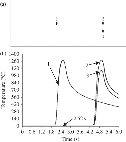
The temperatures at different fixed points were analysed when the laser scanning speed was 200 mm/min. The locations of different fixed points on the upper surface of the powder layer are shown in (a). The distance from point 1 to the left of the powder layer is 8 mm, the distance from point 2 to point 1 is also 8 mm and the vertical distance between point 3 and point 2 is 0.6 mm. The laser spot moves on the upper surface of powder layer from the left end to the right end. (b) shows the temperature changes with time on the upper surface of the powder layer. It shows that the temperature rises rapidly when the laser beam moves to point 1. The temperature gradually decreases when the laser beam moves away. The sintering time is 8 mm/200 mm/min = 0.04 min = 2.4 s when the laser moves to point 1. The time of the maximum temperature is 2.52 s at point 1 from curve 1, as shown in (b). The time of maximum temperature lags the sintering time (about 0.12 s). The corresponding distance is 0.12 s × 10/3 mm/s = 0.4 mm. It shows that the maximum temperature is not at the laser spot centre on the upper surface of the sintered layer. The offset distance is 0.4 mm. The laser beam moves to point 2 after 2.4 s, and the temperature change rule of point 2 is basically the same with point 1. Point 3 lies in the heat-affected zone of the laser spot, whose maximum temperature is lower than that of point 2 due to the distance from point 3 to the laser spot centre, that is, 0.6 mm. The actual highest temperature at point 3 measured was 1055.8 ± 5.4°C with the K-type thermocoupler. The deviation rate is <2%.
Figure 4. The temperature changes with time at different points on the upper surface: (a) the distance from point 1 to the left of the powder layer is 8 mm, the distance from point 2 to point 1 is 8 mm, the vertical distance between points 3 and 2 is 0.6 mm and (b) temperature versus. time.
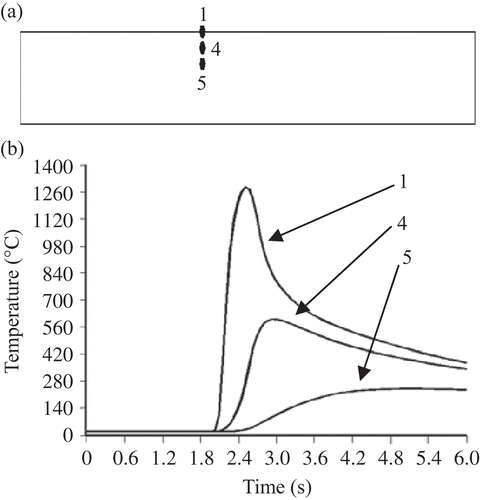
The different fixed points in the thickness of the powder layer are shown in (a). Points 1, 4 and 5 are arranged in a straight line along the sintering depth direction. The distance between points 4 and 1 is 0.4 mm, and the distance between points 4 and 5 is also 0.4 mm. (b) shows the evolution of temperature with time along the longitudinal section of the powder layer when the laser scanning speed is 200 mm/min. It shows that the temperature decreases with the increase of distance along the sintering depth direction, and there is a great temperature gradient.
Figure 5. The temperature changes with time at different points on the longitudinal section: (a) the distance from point 4 to point 1 is 0.4 mm, the distance from point 5 to point 4 is 0.4 mm and (b) temperature versus time.
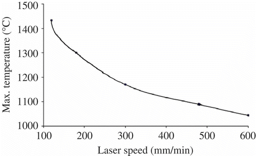
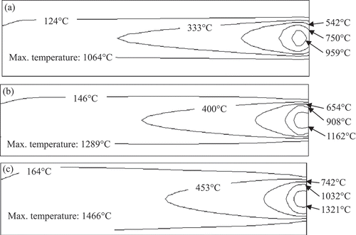
The maximum sintering temperatures versus the different laser scanning speeds are shown in It shows that the maximum temperatures of the sintered layer are 1064°C, 1289°C and 1466°C when the laser scanning speeds are 600, 200 and 120 mm/min, respectively. The maximum temperature of the sintered layer decreases with the increase of laser scanning speed when the other parameters remain unchanged. The reason is that the input laser energy decreases when the laser scanning speed increases, and the temperature decreases when other conditions remain unchanged. Isotherms on the upper surface of the sintered layer with different laser scanning speeds are shown in when the laser spot moves to the right end of the powder layer. It shows that isotherms on the upper surface of the sintered layer are different at different laser scanning speeds.
4. Test experiments
The microstructures of the sintered HAP are different under different sintering temperatures. For example, HAP begins to crystallize, but not completely, and the crystal grows up partly when the sintering temperature is 1100°C [Citation19]. The phase of the synthesized HAP maintains the stability when sintered at 1300°C [Citation20]. HAP decomposes into β-tricalcium phosphate (TCP) and tetracalcium phosphate (TTCP) when the temperature is >1360°C [Citation21].
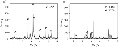
Sintering temperature is different when laser scanning speed is different in the SLS process of nano-HAP powder. The laser sintering experiment of nano-HAP was carried out on a self-developed SLS system when the laser power is 10 W, the spot diameter is 2 mm and the laser scanning speeds are 600, 200 and 120 mm/min, respectively. The test and analysis of sintered nano-HAP were carried out with SEM and XRD at different laser scanning speeds in order to verify the calculation model. SEM images of the nano-HAP are shown in It shows that nanoparticles begin to grow up, but the particles are insufficiently sintered when the laser scanning speed is 600 mm/min. The nano-HAP powders grow up rapidly and bond closely with each other when the laser scanning speed is 200 mm/min. The sintered sample is hard to some extent. The particles completely melt and bond together when the laser scanning speed is 120 mm/min and a small amount of two new phases, TCP and TTCP, exists in the complex when the laser scanning speed is 120 mm/min, which is shown in It indicates that nano-HAP powder is decomposed, which is due to excessive sintering.
Figure 8. SEM images under different conditions: (a) the initial nano-HAP, (b–d) the sintered nano-HAPs when the laser scanning speeds are 600, 200 and 120 mm/min, respectively.
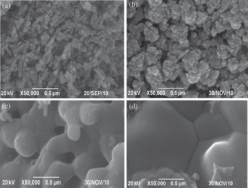
Figure 9. XRD patterns of nano-HAP: (a) the initial powder and (b) the sintered nano-HAP when the laser scanning speed is 120 mm/min.
The simulated results show that the sintering temperatures are 1064°C, 1289°C and 1466°C when the laser scanning speeds are 600, 200 and 120 mm/min, respectively. The test results show that the sintering of nano-HAP can be realized and the decomposition reaction did not happen when the laser scanning speed is 200 mm/min. The corresponding sintering temperature is 1289°C. The decomposition reaction will happen when the laser scanning speed is 120 mm/min, and the corresponding sintering temperature is 1466°C. The test results are in accordance with those of the simulated results.
5. Conclusions
A computation model for 3D transient temperature field in the process of SLS with nano-HAP powder is established. By considering the change of thermal physical parameters and the dynamical loading of the moving laser heat source, we show that the position of the maximum temperature on the sintered layer surface is slightly lagged from the laser spot centre. There is a big temperature gradient at the head of the moving laser heat source and a relatively small temperature gradient at the end of the moving laser heat source. The temperature decreases with the increase of distance along the sintering depth direction, and there is also a great temperature gradient. The test results have been confirmed to be in accordance with the trend by the simulation method. The study provides the instructive role for choosing a reasonable laser sintering process parameters to achieve the better sintering performance.
Acknowledgements
This work was supported by (1) the Natural Science Foundation of China (50875267), (2) the foundation for the author of national excellent doctoral dissertation of PR China (201032), (3) Program for New Century Excellent Talents in University (NCET-10-0792), (4) Open Research Fund of State Key Laboratory of Powder Metallurgy, Central South University, (5) the Open-End Fund for the Valuable and Precision Instruments of Central South University, (6) the Fundamental Research Funds for the Central Universities (2011JQ005), (7) project supported by the Fok Ying-Tong Education Foundation, China (131050) and (8) Open Research Fund of State Key Laboratory of Transient Optics and Photonics, Chinese Academy of Sciences.
References
- Lind , J.E. , Kotila , J. , Syvanen , T. and Nyrhila , O. 2000 . Dimensionally accurate mold inserts and metal components by direct metal laser sintering . Mater. Res. Soc. , 625 : 45 – 50 .
- Kolossov , S. , Boillat , E. , Glardon , R. , Fischer , P. and Locher , M. 2004 . 3D FE simulation for temperature evolution in the selective laser sintering process . Int. J. Mach. Tool. Manu. , 44 ( 2–3 ) : 117 – 123 .
- Zhang , J. , Li , D.Y. , Qiu , B. and Zhao , L.Z. 2011a . Simulation of temperature field in selective laser sintering on PA6/Cu composite powders . J. Adv. Mater. Res. , 213 : 519 – 523 .
- Van Hooreweder , B. , De Coninck , F. , Moens , D. , Boonen , R. and Sas , P. 2010 . Microstructural characterization of SLS-PA12 specimens under dynamic tension/compression excitation . Polym. Test. , 29 : 319 – 326 .
- Zhao , J.F. , You , L. and Zhang , J.H. 2003 . Analysis of the wear characteristics of an EDM electrode made by selective sintering . J. Mater. Process. Technol. , 138 : 475 – 478 .
- Pei-kang , B. , Jun , C. , Bin , L. and Wen-feng , W. 2006 . Numerical simulation of temperature field during selective laser sintering of polymer-coated molybdenum powder . Trans. Nonferrous Met. Soc. , 16 : s603 – s607 .
- Matsumoto , M. , Shiomi , M. , Osakada , K. and Abe , F. 2002 . Finite element analysis of single layer forming on metallic powder bed in rapid prototyping by selective laser processing . Int. J. Mach. Tool. Manu. , 42 : 61 – 67 .
- Ren , J.W. , Liu , J.S. and Yin , J.J. 2011 . Simulation of transient temperature field in the selective laser sintering process of W/Ni powder mixture . J. Int. Fed. Inf. Process. , 347 : 494 – 503 .
- Dong , L. , Makradi , A. , Ahzi , S. and Remond , Y. 2007 . Finite element analysis of temperature and density distributions in selective laser sintering process . Mater. Sci. Forum. , 553 : 75 – 80 .
- Sih , S.S. and Barlow , J.W. 1994 . Measurement and prediction of the thermal conductivity of powders at high temperatures . Solid Freeform Fabrication Symposium Proceedings . August 8–10 1994 . Edited by: Marcus , H. , Beaman , J. , Barlow , J. , Bourell , D. and Crawford , R. Vol. 5 , pp. 321 – 329 . Austin , TX : the University of Texas at Austin .
- Chu , C. , Zhu , J. , Yin , Z. and Wang , S. 1999 . Sintering behaviours and mechanical properties of dense hydroxyapatite (HA) bioceramics . J. Funct. Mater. , 30 ( 6 ) : 606 – 609 .
- Joseph , A. and Nausdle , V. 2005 . Effects of Hydroxyapatite Morphology on MC3T3-E1 Osteoblast-Like Cells , Indiana : University of Notre Dame .
- Chang , F.C. and Tsai , H.L. Modeling of the formation of microporosity in alloys . Transport Phenomena in Material Processing, SME HTD 132 . Edited by: Charmichi , M. , Chyu , M.K. , Joshi , Y. and Walsh , S.M. HTD-Vol. 132 , pp. 73 – 80 . Airfield , NJ : ASME .
- Raghavan , V. , Pope , D.N. and Gogos , G. 2008 . Effect of non-luminous flame radiation during methanol droplet combustion . Combust. Sci. Tech. , 180 : 546 – 564 .
- Liu , S. , Fang , X. , Wan , P. and Yan , J. 2003 . Three-dimensional numerical study on temperature field of laser bending of sheet metal . J. Mater. Sci. Technol. , 19 : 59 – 61 .
- Zhang , J. , Li , D.Y. , Li , J.Y. and Zhao , L.Z. 2011b . Numerical simulation of temperature field in selective laser sintering . Int. Fed. Inf. Process. , 347 : 474 – 479 .
- Cheng , P.J. and Lin , S.C. 2000 . An analytical model for the temperature field in the laser forming of sheet metal . J. Mater. Process. Technol. , 101 : 260 – 267 .
- Patil , R.B. and Yadava , V. 2007 . Finite element analysis of temperature distribution in single metallic powder layer during metal laser sintering . Int. J. Mach. Tool. Manu. , 47 : 1069 – 1080 .
- Han , F. and Wu , L. 2009 . Preparation and characterization of hydroxyapatite bioceramics . J. Ceram. , 30 : 491 – 494 .
- Ramesh , S. , Tan , C.Y. , Sopyan , I. , Hamdi , M. and Teng , W.D. 2007 . Consolidation of nanocrystalline hydroxyapatite powder . Sci. Technol. Adv. Mater. , 8 : 124 – 130 .
- Wang , C. , Quan , R. , Wang , H. , Wei , X. and Zhao , Z. 2010 . Investigation on high-temperature decomposition and regeneration characteristics of both hydroxyapatite powder and sinters . J. Wuhan Uni. Technol. , 32 : 18 – 21 .


