
 ?Mathematical formulae have been encoded as MathML and are displayed in this HTML version using MathJax in order to improve their display. Uncheck the box to turn MathJax off. This feature requires Javascript. Click on a formula to zoom.
ABSTRACT
Lithium metal batteries have recently gained tremendous attention owing to their high energy capacity compared to other rechargeable batteries. Nevertheless, lithium (Li) dendritic growth causes low Coulombic efficiency, thermal runaway, and safety issues, all of which hinder the practical application of Li metal as an anodic material. In this review, the failure mechanisms of Li metal anode are described according to its infinite volume changes, unstable solid electrolyte interphase, and Li dendritic growth. The fundamental models that describe the Li deposition and dendritic growth, such as the thermodynamic, electrodeposition kinetics, and internal stress models are summarized. From these considerations, porous carbon-based frameworks have emerged as a promising strategy to resolve these issues. Thus, the main principles of utilizing these materials as a Li metal host are discussed. Finally, we also focus on the recent progress on utilizing one-, two-, and three-dimensional carbon-based frameworks and their composites to highlight the future outlook of these materials.
Graphical abstract
1. Introduction
During recent decades, research on energy storage systems has grown massively as a result of the escalating global shortage of fossil fuels [Citation1–3]. Li-ion batteries (LIBs) have emerged as a primary source of power for various electrical devices due to their favorable characteristics, such as high thermal stability, energy capacity, durability, and environmental friendliness [Citation4–7]. Even though LIBs can power small, portable electric devices, they are inadequate for long-range electric vehicles (EVs) because of their lengthy charging duration and short operation time. In addition, there is still a demand for higher excess energy storage than what LIBs currently provide to accommodate more electrochemical energy from intermittent renewable resources [Citation8–10]. These resources, such as those harvested from hydroelectric, wind, and solar power, require large-scale and cost-effective energy storage devices with higher capacity [Citation11–14].
Li metal anode has stood out as an ideal candidate, not only due to its ultrahigh theoretical specific capacity (3860 mA h g−1), but also its lowest redox potential among the alkali metals (−3.04 V vs. standard hydrogen electrode), and light weight (0.53 g cm−3). In particular, the specific energy density of Li metal batteries (LMBs) is expected to reach as high as 700 W h kg−1 [Citation15,Citation16]. Moreover, LMBs have gained substantial interest, including all-solid-state LMBs as well as Li-S and Li-air batteries, where the energy density was speculated to reach 2600 W h kg−1 for Li-S and 11,680 W h kg−1 for Li-air [Citation15–19]. Nevertheless, Li metal suffers from severe drawbacks that hinder its usage in practical applications, including unstable or uneven solid-electrolyte interphase (SEI), the formation of dead Li, dendrite growth, and volume changes during plating and stripping processes. These lead to severe issues, such as short-circuiting, low Coulombic efficiency (CE), capacity loss, and safety complications [Citation17,Citation20,Citation21]. Consequently, a plethora of research studies has been devoted to overcoming the failure mechanism of the LMBs, including stabilizing the SEI using electrolyte additives, preventing dendrite penetration via artificial SEI layers of high modulus or solid-state electrolytes, and guiding uniform Li deposition by utilizing three-dimensional (3D)-constructed porous hosts. Among these strategies, the latter technique has gained tremendous attention [Citation22,Citation23].
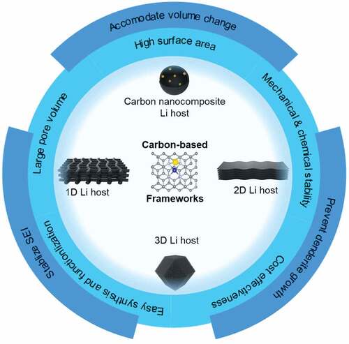
One of the candidates with the greatest potential for cost-effective practical usage of 3D-constructed porous hosts is carbon-based frameworks, as they exhibit several outstanding properties [Citation18,Citation22], and has been integrated in multiple applications [Citation24–29]. In details, a carbon-based framework has excellent electrical conductivity that facilitates continuous electron transport and limits electrode polarization. Moreover, the large surface area of the carbon-based framework reduces the local current density of the anode and prevents dendrite growth by tuning the lithiophilicity of the surface. In addition, the pore network inside the carbon-based framework shows high electrochemical stability and can store a large amount of metallic Li while maintaining the structural integrity of the electrode. Finally, a carbon-based framework exhibits robust mechanical strength that permits volume change accommodation and internal stress resistance [Citation30–33].
In this review, we first briefly summarize our fundamental understanding of the failure mechanism of the LMBs, including Li dendrite growth, instability of the SEI, and significant volume changes. Then, the main principles for utilizing carbon-based frameworks as Li host material will be discussed, including carbon wettability. We also highlight the recent progress on developing stable framework materials, focusing on using one-, two-, and three-dimensional (1D, 2D, and 3D) frameworks as a feature of nanocomposites as host materials. Finally, we provide a future perspective on the characterization mechanisms of carbon host materials to improve the energy density toward more efficient LMBs.
2. Failure mechanism of Li metal anode
The failure mechanisms of the Li metal anodes are primarily associated with uncontrollable dendritic Li growth, infinite volume changes, and the unstable SEI, which all occur during electrochemical cycling, as shown in [Citation34–38].
Figure 1. Schematic illustration of the failure mechanisms that occur in Li metal anode; Infinite volume expansion of Li metal causes instability of SEI and induces mechanical stresses that destroy the integrity of the anode. Extremely thick SEI layer causes high interfacial impedance. The dendritic growth forms in various dendritic structures, such as trees and whiskers. The further extension of these Li dendrites can lead to a loss in their electric contact with the anode during stripping, resulting in ‘dead Li’. Furthermore, long dendrites can cause short circuits.
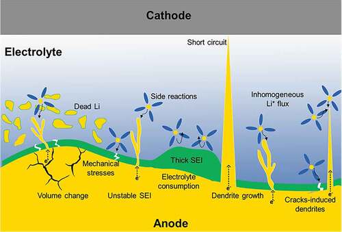
2.1 Infinite volume change
Volume change of the battery during operation is a common serious issue, which afflicts almost all commercially available electrode materials. For example, the ‘rocking chair’ model shows that the volume changes of graphite- and silicon-based electrodes are limited to 10% and 400%, respectively [Citation17,Citation20]. Utilizing bare Li metal as an anode, on the other hand, causes infinite volume expansion due to its ‘hostless’ nature. The problem starts with the Li interface movement during the stripping/plating process, in which the volume expansion could reach up to tens of micrometers in thickness, imposing SEI instability (see ). In addition, the significant volume changes may induce mechanical stresses that destroy the integrity of the anode, and increase electrode impedance and capacity fade [Citation7,Citation23].
2.2 Unstable solid-electrolyte interphase (SEI)
Conceptually, the electrolyte reduction on the surface of the electrode forms a bilayer SEI film, which consists of a main layer that directly grows on the anode surface and a second porous layer that originates from the solution side. Therefore, the SEI can block electrons and conducting ions. In normal circumstances, the formation of the SEI film on the battery’s electrode can eliminate excessive reactions between the electrode and electrolyte. Utilizing Li metal as the anode, however, can result in a fragile and unstable SEI with variable morphology and thickness, owing to the high reactivity of Li and infinite volume change () [Citation35]. This takes place during battery cycling, in which the Li anode surface can spontaneously react with various polar-aprotic electrolyte solvents and salts. In addition, the morphology of the Li metal deposited on the electrode surface is highly affected by the diffusion behavior through the SEI layer. In other words, an extremely thick SEI layer, as shown in , causes high interfacial impedance while an extremely thin SEI layer cannot protect the electrode from side reactions [Citation17]. Furthermore, the irreversible Li depletion usually degrades the CE of LMBs, which severely affects its overall performance and becomes the main obstacle to practical applications. In addition, the SEI continues to react and consume more fresh Li ions to compensate for the breaking of its integrity, which eventually leads to low CE and faded capacity [Citation17,Citation39].
2.3 Dendritic growth
Dendritic growth is a well-known phenomenon that emerges during metal electroplating. The Li-ions within the electrolyte acquire electrons and are deposited on the surface of the anode, forming various dendrite structures, such as trees, snowflakes, needles, and whiskers [Citation40–43]. The ungovernable generation of dendrites during battery cycling increases the surface area of the electrode, which increases the side reactions between the electrolyte and the Li metal. Consequently, the Li-ions would favor the dendrites as their deposition surface due to the stronger electric fields and larger electroactive surfaces, inducing more unnecessary side reactions. This results in rapid consumption of the electrolyte, and accelerating capacity fading, (see ) [Citation42]. Moreover, the further extension of a Li dendrite can lead to the loss of its electronic contact with the electrode during stripping, a phenomenon called ‘dead Li’, which reduces the active material, minimizes the surface area, and renders huge impedance. Moreover, the continuous growth of the Li dendrites can generate sharp and long ones that could reach the surface of the cathode while penetrating the separator, causing an inner short circuit within the electrochemical cell. Short circuits are accompanied by heat dissipation, and thus electrical fires and explosions, as illustrated in [Citation34,Citation42,Citation44].
3. Li deposition and dendritic growth
As explained in the previous section, dendritic Li growth causes many significant challenges that hinder the practical application of LMBs. Hence, realizing the main factors that play a role in the dendritic growth is the first step, including the failure mechanisms and appreciating the importance of utilizing engineered carbon-based frameworks as a powerful solution.
3.1 General models of Li formation and dendritic growth
During the last four decades, many theoretical models have been established to investigate the factors and processes responsible for dendritic growth. This section discusses some standard essential models.
At the beginning of the Li plating process, the Li-ions start migrating to the electrode surface under the dual effects of the concentration gradient and the electric field. The Li-ions will be reduced and start nucleating, in which the speed of Li-ion consumption and deposition relies on the applied current density [Citation23,Citation40,Citation45]. Therefore, the cathode begins to supply Li ions to macroscopically compensate for the Li-ion depletion at the anode, which also relies on the applied current density. Hence, the microscopic distribution of these ions at the anode governs the overall deposition morphology. For this reason, Brissot et al. have provided one of the most widely acceptable models that demonstrates the dendritic growth mechanism based on the concentration gradient near the electrode [Citation46–48], as illustrated in the following equation:
where e is the electric charge, D is the ambipolar diffusion coefficient, C is the Li+ concentration in the electrolyte, is the effective current density,
is the anionic mobility, and
is the Li-ion mobility.
The change in ionic concentration ( C/
x) from the anode to the cathode is linearly correlated to J. In contrast, two different types of behavior are expected from a Li symmetric cell at low and high applied current densities, depending on the initial concentration, C0, D, and the inter-electrode distance (L). At a low current density, when
C/
x < 2 C0/L, the deposition of Li ions shows a smooth surface morphology. In contrast, at a high current density, when
C/
x > 2 C0/L, the Li-ion and anionic concentrations behave differently at a certain point, forming a localized space charge. This results in a large electric field, thus inducing dendritic growth. More specifically, Chazlviel et al. described the relationship between the current density (J) and the time at which the ionic concentration vanishes at the anode, denoted as Sand’s time (τ). The Sand’s time is inversely proportional to J2, so that a high value of τ means that a longer time is needed for Li deposition [Citation49]. This correlation and other influential factors are presented in the following equation:
where ta is the anionic transference number. A low value means that the dendritic growth will initiate in a shorter time. The Chazalviel model is considered as one of the most reliable models that simulates and predicts the Li deposition behavior at high current density. Other experimental results and models, however, have clearly demonstrated that the Chazalviel model can also be extended to low current densities. This was attributed to the local fluctuations of current density on the anode surface [Citation50–52].
For example, one study by Cheng et al. showed that mossy-like (2D) dendrites are induced at low current densities due to the kinetic limitations of Li reduction () [Citation43,Citation44,Citation53]. The high current density, in contrast, causes three-dimensional dendritic growth due to rapid Li-ion depletion in the proximity of the electrode surface. Another recent study, Bai et al., explains the dendritic growth analytically at various current densities using a nanoporous ceramic separator and Li metal anode () [Citation54,Citation55]. First, if the current density is less than its critical value (J < Jcc), the mechanism of dendrite growth is called ‘root-growth’, and the structure becomes whisker-like. In this case, the SEI remains intact, and the deposition occurs beneath until it reaches a certain point of time when pinholes in the SEI begin to release pressure in the form of whisker-like dendrites (). The whiskers protrude as wires from the SEI surface when the deposition continues further. On the other hand, if the current density is more than the diffusion-limited current density (J > Jlim), the aforementioned Chazalviel model is applied, where tree-like dendrite structures form (). Bai et al. added to this model an additional interesting regime in between (Jcc < J < Jlim), where the intermediate current density is applied at a rate that is similar to the rate of SEI formation. This causes mossy-like dendritic growth with a non-uniform interfacial layer ().
Figure 2. A) Schematic illustration showing the early stages of Li dendritic growth at different current densities Reproduced with permission from [Citation44], Copyright 2021, Wiley. b) The different types of Li dendritic growth and their interactions with a nanoporous alumina separator under different current density conditions. AAO: anodic aluminium oxide Reproduced with permission from [Citation54], Copyright 2018, Science.
![Figure 2. A) Schematic illustration showing the early stages of Li dendritic growth at different current densities Reproduced with permission from [Citation44], Copyright 2021, Wiley. b) The different types of Li dendritic growth and their interactions with a nanoporous alumina separator under different current density conditions. AAO: anodic aluminium oxide Reproduced with permission from [Citation54], Copyright 2018, Science.](/cms/asset/535cc7ed-beaf-4453-93a8-95e8ec803c56/tsta_a_2050297_f0002_oc.jpg)
Another model, proposed by Monroe and Newman, addressed the growth rate of the dendrites under different galvanostatic conditions [Citation56,Citation57]. The model demonstrated that the local electric field is intensely increased at the tip of a dendrite, inducing further Li deposition from the electrolyte and thus accelerating its growth.
Additional thermodynamic factors also contribute to the dendritic growth besides the kinetic factors. Ely et al. designed analytical frameworks for reaction-rate-limited systems to anticipate Li growth and nucleation during electrodeposition [Citation58]. The work showed different five regimes of nucleation behavior, including short incubation time, long incubation time, nucleation suppression, early growth, and late growth (). In the nucleation suppression regime, the embryos were unable to persist and thermodynamically unstable, which possibly caused them to dissolve back into the electrolyte. In the long incubation time regime, the embryos were in a thermodynamically favored and metastable condition, in which they persisted without growing until they were subjected to thermal variations. In the short incubation time regime, narrow-sized embryos started to nucleate faster with increasing overpotential. Thermodynamic and kinetic stability in the growth of nuclei were displayed in the early growth regime, where the growth rate reached the constant terminal velocity. Eventually, the late growth regime included unstable morphologies that were dominated by the localized electric fields, as shown in .
Figure 3. The main regimes of the initial stage behavior of Li nucleation and growth. a) Above the black bold curve, there is a zone of stable Li growth. Below the blue curve is the undesirable Li growth zone. The solid grey curves represent the fixed incubation times. The dotted grey curves highlight the initial velocities of Li nucleation Reproduced with permission from [Citation58], copyright 1948, Electrochemical Society. b) Schematic illustration of the size and density of Li nuclei deposited on Cu current collectors at different nucleation overpotentials Reproduced with permission from [Citation59], copyright 2017, American Chemical Society.
![Figure 3. The main regimes of the initial stage behavior of Li nucleation and growth. a) Above the black bold curve, there is a zone of stable Li growth. Below the blue curve is the undesirable Li growth zone. The solid grey curves represent the fixed incubation times. The dotted grey curves highlight the initial velocities of Li nucleation Reproduced with permission from [Citation58], copyright 1948, Electrochemical Society. b) Schematic illustration of the size and density of Li nuclei deposited on Cu current collectors at different nucleation overpotentials Reproduced with permission from [Citation59], copyright 2017, American Chemical Society.](/cms/asset/ea24b2d8-97f1-45be-adb3-6c1b17786b0f/tsta_a_2050297_f0003_oc.jpg)
A recent study by Pei et al. that investigated the Li deposition morphology at different current densities, illustrated the dependence of the shape, size, and areal density of Li nuclei on the current rate, as shown in [Citation59]. This aligns with the classical nucleation and growth theory, as they found that the size of the nuclei is inversely proportional to the nucleation overpotential and that the density of the nuclei is directly proportional to the cubic power of the overpotential.
The deposition and solution model has demonstrated that mechanical stress causes dendritic growth [Citation23,Citation60]. The Laplace’s Equationequation (2)(2)
(2) shows the relationship between surface tension (
), pressure difference (
), and orthogonal curvature radii (R1, R2) as described:
on the basis of this model, Yamaki et al. conducted a study on utilizing hard films with surface tension of more than 0.2 N/m to prevent dendrite penetration mechanically, acting as a blocking layer [Citation61,Citation62].
The studies and theories mentioned above provide a comprehensive understanding of the main mechanisms and factors contributing to dendritic growth, which paves the way toward designing and engineering stable anode materials utilizing a carbon-based framework.
4. Principles toward utilizing carbon-based frameworks as Li host materials
Based on the aforementioned models and discussion, tremendous attention has been drawn toward designing Li host frameworks to regulate and stabilize the LMBs. Carbon matrices, such as graphite felts, carbon nanotubes, graphene, hollow carbon nanospheres, and carbon foams, are among the most researched candidates owing to their easily controlled properties, cost-effectiveness, and easy synthesis and functionalization for real practical applications of LMBs [Citation18,Citation63–67]. In this section, the main principles that must be considered to utilize carbon matrices as Li host materials will be discussed.
As inferred earlier, the initial nucleation of dendritic growth and its rate is mainly affected by the non-uniform distribution of the Li-ion flux on the electrode surface, which arises from the enormously high local current density. To slow down the nucleation of dendrites, carbon-based frameworks were initially designed to offer a larger surface area that increases Sand’s time by decreasing the local current density (J). Nevertheless, unwanted massive electrolyte consumption might occur during the SEI formation due to the large electrode/electrolyte interface area. As a result, the impedance for Li-ion transport may increase, leading to premature death of the LMB [Citation63,Citation68–70].
This concept was demonstrated by Jeong et al., who compared two different pore sizes and surface areas of carbon material () [Citation71]. The microporous carbon (MSP-20) with a pore size of < 2.0 nm and a surface area of 2110 m2g−1 showed a significant decrease in the CE after the 80th cycle and faded at around the 110th cycle. In contrast, the mesoporous carbon (CMK-3) with a pore size of 3.4 nm and a surface area of 1120 m2g−1 exhibited stable cycling up to 200 cycles and a CE of > 95%. The results of this study provide evidence that surface area is not the only factor that affects the dendrite growth, but also the pore size.
Figure 4. A) Schematic representation of the effects of different pore sizes on Li deposition behavior Reproduce with permission from [Citation71], copyright 2020, The Royal Society of Chemistry. b) The hollow carbon nanospheres act as a scaffold to stabilize the SEI layer. The scanning electron microscopy (SEM) image on the right displays no dendritic growth after Li deposition Reproduce with permission from [Citation74], copyright 2014, Nature. c) Schematic illustration of the behavior of Li plating on an electrical conductivity-controlled 3D host and a 3D conductive host. The SEM images present different views of the pristine partially reduced graphene oxide ‒graphene foam (PrGO–GF)/Cu electrode Reproduce with permission from [Citation89], copyright 2021, Royal Society of Chemistry. d) LiF-rich SEI formation on Co-ZIF-C electrode stabilizes the cycling performance. The SEM image shows no dendritic growth after cycling Reproduce with permission from [Citation90], copyright 2021, Springer.
![Figure 4. A) Schematic representation of the effects of different pore sizes on Li deposition behavior Reproduce with permission from [Citation71], copyright 2020, The Royal Society of Chemistry. b) The hollow carbon nanospheres act as a scaffold to stabilize the SEI layer. The scanning electron microscopy (SEM) image on the right displays no dendritic growth after Li deposition Reproduce with permission from [Citation74], copyright 2014, Nature. c) Schematic illustration of the behavior of Li plating on an electrical conductivity-controlled 3D host and a 3D conductive host. The SEM images present different views of the pristine partially reduced graphene oxide ‒graphene foam (PrGO–GF)/Cu electrode Reproduce with permission from [Citation89], copyright 2021, Royal Society of Chemistry. d) LiF-rich SEI formation on Co-ZIF-C electrode stabilizes the cycling performance. The SEM image shows no dendritic growth after cycling Reproduce with permission from [Citation90], copyright 2021, Springer.](/cms/asset/be66dca7-aefa-4124-b985-fb7a411c4429/tsta_a_2050297_f0004_oc.jpg)
The high mechanical stability and flexibility of a carbon-based framework are essential properties to stabilize the SEI by alleviating volume change, suppressing the Li dendrite growth, and inhibiting the electrode disintegration. These properties make the SEI less susceptible to swelling-related stresses and fluctuations during Li plating/stripping cycles [Citation18,Citation31,Citation33,Citation72,Citation73]. One study, conducted by Zheng et al. provided evidence that interconnected amorphous hollow carbon nanospheres, acting as a monolayer coating for Li metal anode, as shown in , help in isolating the deposition of Li metal and facilitating the formation of a stable SEI [Citation74]. In another study, conducted by Liu et al., a 3D porous structure was constructed as a Li metal host, which was made of carbon cloth and interconnected carbon nanotubes (CNTs) (CC/CNT) [Citation75]. The results showed that the porous structure of CC/CNT offered enough space to suppress volume changes, whereas the CNTs on the top surface acted as active sites to reduce the local current density. Consequently, a stable SEI was formed, and battery life was extended.
For practical application, a large pore volume and low mass density are necessary to increase the gravimetric capacity by holding more lithium inside the host materials while maintaining the structural integrity of the electrode [Citation76–78]. For example, to achieve a gravimetric energy capacity of 3860 mA h cm−2 for 1 g of Li metal, the volume required is 1.87 cm3. This means the host materials should offer a large pore volume to accommodate the lithium and increase its energy storage properties [Citation79,Citation80]. Theoretically, the gravimetric capacity of carbon-based frameworks can be calculated via the following equation:
where is the theoretical gravimetric capacity,
is the theoretical volumetric capacity of carbon,
is the volumetric capacity of Li,
is the pore volume, and
and
are the masses of the carbon frameworks and the Li-metal, respectively. Although high pore volume is the desired property, carbon-based frameworks usually exhibit low reversibility in terms of areal capacity. A study that employed a Li-metal-filled carbon fiber network as a host material, showed that while the gravimetric and areal capacities were enhanced by 2000 mA h g−1 and 19 mA h cm−2, respectively, the reversibility was for one discharge only [Citation81]. Typically, practical applications of Li-metal anodes require a reversible areal capacity that is higher than 5 mA h cm−2, which most studies in the literature have not yet accomplished. Therefore, other factors were investigated to increase the reversibility, including the pore size and depth [Citation82]. As discussed earlier in , micropores show resistance to Li storage, while mesopores show higher Li storage and reversible capacity. The morphology of the Li deposition is also governed by the pore depth, as the distribution of electric field can be altered by tuning the pore depth as well as the chemistry of the host material, which will be discussed in the following section [Citation83,Citation84].
The electrical conductivity of the host material is another crucial aspect to consider when designing the carbon-based framework, because it facilitates continuous electron transport and limits electrode polarization. Therefore, a highly conductive framework can result in fast Li-ion transportation and capture [Citation78]. Nevertheless, if the electrical conductivity of the host material is non-uniform, this could result in irregular Li deposition, since the regions of higher electrical conductivity quickly capture more Li ions compared to other regions of lower conductivity [Citation85–87]. Creating a conductivity gradient within the Li host is an effective strategy that is used to generate more current flow in bottom deposition [Citation88]. A 3D conductive framework was introduced by Park et al. that ultimately mitigated the dendrite growth by integrating non-conductive glass fiber or polyacrylonitrile (PAN) as a top membrane, as shown in [Citation89]. This layer induced a conductivity gradient that ensured a proper distribution of Li-ion flux and regulated the bottom-up Li deposition, enhancing the overall performance.
The chemical stability and composition of the carbon-based framework are additional properties that prevent side reactions with the electrolyte under the redox environment and maintain a robust SEI, respectively [Citation18,Citation72]. Lee et al., for instance, demonstrated the role of cobalt (Co) nanoparticles, which were integrated into a porous carbon framework, in forming a thick lithium fluoride layer that dominated the SEI in ether-based electrolytes [Citation90]. The results showed that the host anode containing Co nanoparticles exhibited an outstanding electrochemical performance with a high CE and a stable long-term operational lifespan (see ).
5. Wettability of carbon-based frameworks
In normal circumstances, the mechanism of electroplating is known to start when the Li-ions approach the anode from the bulk electrolyte, after which, they shed off the solvent molecules to reduce themselves and transform to Li adatoms. Following this, the Li adatoms diffuse on the surface of the anode until they become incorporated into the metal lattice [Citation91]. This is not the ideal case, however, as weak interactions and a high diffusion barrier are expected, which make the Li metal thermodynamically susceptible to dendritic growth. Based on this, a detailed understanding of the chemistry of the carbon-based framework and its structure needs to be considered. These materials might suffer from poor Li wettability, which results in significant nucleation and diffusion barriers as well as upper surface electrodeposition of Li metal [Citation1,Citation17,Citation38,Citation43,Citation58,Citation92].
The pore structures and the lithium wettability of the carbon-based frameworks are of special importance according to the classical heterogeneous nucleation theory, which explains the dependence of the nucleation barrier on the lithium wettability of the anode material, as described in the following equation:
where and
are the heterogeneous and homogeneous nucleation barriers, respectively. The heterogeneous nucleation barrier
is also determined by the shape factor
, which corresponds to the surface morphology of the substrate and changes its value according to the presence of pores, as shown in . The nucleation barrier does not exist when the angle between the host material and the Li metal nucleus is equal to zero. If the angle comes close to 180 degrees, in contrast, the heterogeneous nucleation barrier is at its maximum and equals the homogenous nucleation barrier. In summary, the lower the Li wettability, the greater is the nucleation barrier as well as the critical radius to form nuclei, resulting in dendrite growth [Citation93].
Figure 5. A) Schematic illustration of how lithiophilic pores within a suitable host material can store the Li-metal. When the sum of the half angle of the cavity and the contact angle of the nucleus on the substrate is below 90°, the energy barrier will be zero Reproduced with permission from [Citation15], copyright 2020, Elsevier. b) Typical voltage profile of galvanostatic Li deposition (black) and double pulse potentiostatic Li deposition (red) Reproduced with permission from [Citation59], copyright 2017, American Chemical Society. c) Modelling of heteroatom-doped carbon versus pristine graphene model. The bar chart below is a summary of the calculated binding energy between different heteroatom-doped carbons and a Li atom Reproduced with permission from [Citation91], copyright 2019, Science.
![Figure 5. A) Schematic illustration of how lithiophilic pores within a suitable host material can store the Li-metal. When the sum of the half angle of the cavity and the contact angle of the nucleus on the substrate is below 90°, the energy barrier will be zero Reproduced with permission from [Citation15], copyright 2020, Elsevier. b) Typical voltage profile of galvanostatic Li deposition (black) and double pulse potentiostatic Li deposition (red) Reproduced with permission from [Citation59], copyright 2017, American Chemical Society. c) Modelling of heteroatom-doped carbon versus pristine graphene model. The bar chart below is a summary of the calculated binding energy between different heteroatom-doped carbons and a Li atom Reproduced with permission from [Citation91], copyright 2019, Science.](/cms/asset/2c6baf7e-e23c-450b-92cc-7d5b09a404d4/tsta_a_2050297_f0005_oc.jpg)
On the basis of the classical heterogeneous nucleation theory, the lithiophilicity of the anode is quantitively described by the nucleation overpotential. Primarily, the overpotential can be divided into three regimes, (). The first one is the initial steep fall in the overpotential of nucleation, which indicates the SEI formation. The second regime is the sharp negative spike in the overpotential, which indicates the formation of the Li metal nuclei. The spike indicates the electrochemical supersaturation needed to overcome the nucleation barrier for Li plating. The last regime is when the overpotential rises to a plateau due to the post nucleation growth phase of the Li nuclei. This is because adding a Li adatom to an existing Li nucleus is more favorable and has a lower energy barrier than forming a seed of Li metal [Citation21,Citation94].
A comprehensive understanding of the lithiophilic nature of heteroatom-doped carbon-based frameworks was demonstrated by a theoretical study conducted by Chen et al. The binding energy between a lithium atom and heteroatom-doped carbon was calculated for various cases (), including pyrrolic nitrogen (rN), a carboxylic group (aO), graphitic boron on the edge (egB), graphitic boron in the bulk phase (bgB), B-2C-O-type boron (oB), a ketone group (kO), quaternary nitrogen (bqN), quaternary nitrogen on the edge (eqN), pyridinic nitrogen (pN), cyclic oxygen (cO), an epoxy group (eO), a hydroxyl group (hO), F, Cl, Br, I, P, S, and a sulfonyl group (oS) [Citation91]. The simulation results suggested three basic principles that could be used to improve the lithiophilicity of the anode substrate, in terms of electronegativity, charge transfer, and local dipoles. The upshot of the study was that the Li ions, acting as a Lewis acid, are strongly attracted to heteroatoms, which act as Lewis base sites owing to their high electronegativity. The functional groups with B, N, and O are found to decrease the Li nucleation overpotential. In contrast, Cl, I, S, F, and Br do not provide high electronegativity toward Li atoms. The second principle includes enhancing the binding energy via co-doping as a strategy to induce a strong local dipole, such as O-S/B/P co-doping. Finally, it was determined that a critical charge transfer above 0.9 e− is required to increase the binding energy, suggesting that charge transfer has a crucial role during Li nucleation.
6. Recent progress on designing carbon-based frameworks (1D, 2D, 3D) and composites
The use of carbon-based frameworks has recently become a highly favorable strategy that can stabilize the electrochemical reactions and enhance the safety of Li metal anodes. In practice, any carbon-based framework needs to exhibit some basic requirements to improve the performance of the anode, including light weight, chemical and mechanical stability, high surface area, large pore volume, sufficient conductivity, and most importantly, lithiophilicity. Understanding the dimensionality of the host material and its corresponding properties is important for constructing a highly efficient anode. This section will discuss the recent progress on utilizing 1D, 2D, and 3D carbon-based frameworks, and their nanocomposites.
6.1. 1D carbon
6.1.1 Carbon fibers
Carbon fibers (CFs) come in a 1D structure with diameters that range from the nano- to the microscale. Besides its outstanding mechanical properties, CFs can be mass-produced in a cost-effective way to facilitate the quantitative integration of electrode materials. The main purpose of employing CFs in the anode is to offer a high surface area that enhances the Li-ion flux. A multifunctional current collector was constructed by Niu et al. that utilized graphitized carbon fibers (GCF) to enlarge the Li storage capacity by intercalation and plating reactions [Citation95]. In addition, using GCF provided a porous structure, which increased the surface area and mitigated volume changes. The enhanced electrochemical performance of this designed anode structure was proved by its large areal capacity of 8 mA h cm−2, high CE of 98% for 50 cycles, and low nucleation overpotential of 10 mV. () Another approach was adopted by Niu et al., where mesoporous carbon nanofibers were functionalized by amine groups while monitoring the battery stability under practical conditions, as shown in . Interestingly, in this study, it was found that the mesoporous carbon structure and the amine groups facilitated the self-smoothing of Li during the deposition process and enabled the carbon hosts to be superwetting towards Li [Citation96]. These results were reflected by the electrochemical performance of the battery, in which the areal capacity was 1.25 mA h cm−2 for 1000 cycles at a current density of 1.25 mA cm−2.
Figure 6. A) SEM images showing the morphology of the pristine GCF, intercalated GCF, and GCF charged up to 2 mAh cm−2. The galvanostatic discharge profile with inset schematic diagrams of lithium behavior during cycling is shown below. All scale bars in (a) are 10 µm Reproduce with permission from [Citation95], copyright 2017, Wiley. b) The schematic illustration on the left shows that the pristine carbon is not Li-wetting, but after being functionalized with heteroatoms, it becomes superwetting. The schematic illustration on the right side shows that, after functionalizing graphitized fiber carbon (GFC) with amine groups, it becomes superwetting, and the Li grows axially. The cycling performance and CE of Li-C||NMC622 and Li||NMC622 cells, demonstrating long-term cycling. An SEM image of amine functionalized GFC shows smooth growth of Li Reproduce with permission from [Citation96], copyright 2019, Nature.
![Figure 6. A) SEM images showing the morphology of the pristine GCF, intercalated GCF, and GCF charged up to 2 mAh cm−2. The galvanostatic discharge profile with inset schematic diagrams of lithium behavior during cycling is shown below. All scale bars in (a) are 10 µm Reproduce with permission from [Citation95], copyright 2017, Wiley. b) The schematic illustration on the left shows that the pristine carbon is not Li-wetting, but after being functionalized with heteroatoms, it becomes superwetting. The schematic illustration on the right side shows that, after functionalizing graphitized fiber carbon (GFC) with amine groups, it becomes superwetting, and the Li grows axially. The cycling performance and CE of Li-C||NMC622 and Li||NMC622 cells, demonstrating long-term cycling. An SEM image of amine functionalized GFC shows smooth growth of Li Reproduce with permission from [Citation96], copyright 2019, Nature.](/cms/asset/07332a3b-8665-4894-b02b-af2e6a1fce53/tsta_a_2050297_f0006_oc.jpg)
6.1.2 Carbon nanotubes
Carbon nanotubes (CNTs) have a unique 1D structure that enables fast ion and electron conduction, so that they serve as ideal candidates for anodes that perform under high current densities. The light weight, expandability, and mechanical robustness of the CNT play a significant role in enhancing the reversible capacity of batteries. One research study, conducted by Sun et al., showed the benefits of these properties by using CNT paper as a conductive framework to increase the Li metal storage by 80.7 wt % [Citation82]. The physical and mechanical nature of this sp2-hybridized carbon framework permitted a high CE of > 97.5% for 1000 cycles at a current density of 10 mA cm−2 and a high areal capacity of 10 mA h cm−2 (see ). To enhance the lithiophilicity of their CNT framework, Liu and co-workers introduced oxygen into the CNTs as a doping material (O-CNT) [Citation97]. The theoretical and experimental results proved that the ketonic group (C = O) enhances the Li wettability of the anode, which was quantitively measured by its lower nucleation overpotential (35 mV). Moreover, the porous structure of the 3D O-CNT conductive network facilitated Li-ion and electron transport with long-term durability, which was reflected in the electrochemical performance of the battery (see ).
Table 1. Electrochemical performances of Li-metal anodes utilizing 1D carbon-based frameworks
6.2 2D carbon
Graphene is a 2D monolayer of carbon atoms that are oriented into a hexagonal honeycomb‐like lattice, which provides superior electrical conductivity, high surface area, and mechanical flexibility and stability. Therefore, many studies have focused on integrating graphene in LMBs. For example, Li et al. utilized self-assembled reduced graphene oxide (rGO) as a carbon-based framework, owing to its compact layer-by-layer structure and smooth surface [Citation98]. Interestingly, they obtained epitaxial and dense lithium electrodeposition, even at a high current density of 20 mA cm−2. The deposition mechanism behind achieving planar (110) crystallographic planes of lithium crystal is related to the in-plane lattice matching between two Li atoms, which have atomic length of 4.96 Å along the (110) plane, and two carbon hexagons, which have length of 4.92 Å in the zigzag direction of graphene (See ). The performance of the dendrite-free rGO-based anode was demonstrated by its high CE of 99% for 300 cycles at a current density of 1 mA cm −2 and a capacity density of 1 mA h cm−2. Another study, conducted by Zhang et al., designed N-doped graphene as an Li plating matrix to control Li nucleation and inhibit dendritic growth [Citation99]. The pyrrolic nitrogen and pyridinic nitrogen functional groups displayed favorable lithiophilicity due to the relatively small nucleation barrier, which yielded a uniform distribution of the Li metal on the electrode substrate compared to pristine graphene and Cu anodes. Such guided Li nucleation resulted in dendrite-free morphology during cyclic Li plating, and the cell exhibited a high CE of 98% over nearly 200 cycles (see ). Additionally, a study was conducted by Liu et al. that utilized CoNx-doped graphene to obtain high stability and high CE of 99.2% within 400 cycles. They reported that the existence of CoNx as heteroatoms in graphene enhanced the adsorption of the lithium ions and promoted uniform nucleation as well as smooth lithium deposition (see ) [Citation100].
Table 2. Electrochemical performances of Li-metal anodes utilizing 2D carbon-based frameworks
Figure 7. A) Schematic illustration of the axial growth of Li on an rGO substrate. The red dashed lines are the graphene zigzag lattice directions. The electrochemical performance of the rGO demonstrates the stability of the symmetrical cell up to 500 hours SEM images of the rGO show the axial growth of the Li metal. Scale bars in (a) are 100 µm and all scale bars in insets are 50 µm Reproduced with permission from [Citation98], copyright 2020, Wiley. b) Schematic illustration of different doped heteroatoms in the graphene. The middle bar chart illustrates the binding energy calculated between the Li atom and different functional groups. The schematic illustration below and inset SEM image show the smooth Li growth. The right-side schematic shows the total electron density (blue) of isolated atoms on graphene and pyrrolic-N. The red regions indicate less electron density Reproduced with permission from [Citation99], copyright 2020, Wiley.
![Figure 7. A) Schematic illustration of the axial growth of Li on an rGO substrate. The red dashed lines are the graphene zigzag lattice directions. The electrochemical performance of the rGO demonstrates the stability of the symmetrical cell up to 500 hours SEM images of the rGO show the axial growth of the Li metal. Scale bars in (a) are 100 µm and all scale bars in insets are 50 µm Reproduced with permission from [Citation98], copyright 2020, Wiley. b) Schematic illustration of different doped heteroatoms in the graphene. The middle bar chart illustrates the binding energy calculated between the Li atom and different functional groups. The schematic illustration below and inset SEM image show the smooth Li growth. The right-side schematic shows the total electron density (blue) of isolated atoms on graphene and pyrrolic-N. The red regions indicate less electron density Reproduced with permission from [Citation99], copyright 2020, Wiley.](/cms/asset/6ea8cf1d-556f-48d9-9317-361ae51da772/tsta_a_2050297_f0007_oc.jpg)
6.3 3D carbon
Carbon materials with 3D structures have desirable characteristics in terms of cost-effectiveness, easy synthesis and functionalization, controllable microstructures, electrical conductivity, and high surface area. Thus, this type of carbon structure is considered as one of the most practical candidates for industrial production. Investigations of guiding homogeneous Li plating via 3D carbon frameworks were conducted by Liu et al., who used lightweight, flexible nitrogen-doped graphitic carbon foam (NGCF) in situ [Citation101]. The presence of N-containing functional groups, including pyridinic N and pyrrolic N, in the anode design, enabled dendrite-free Li electroplating and enhanced the electrochemical performance even at high areal capacity of 10 mA h cm−2. (See ) This was evidenced by the low nucleation overpotential (< 25 mV at 3 mA cm−2) and the high CE (99.6%) for 300 cycles. In another study, Kim et al. utilized Zn/N doped porous carbon framework (PCF), which was derived from ZIF-8, where ZIF is zeolitic imidazolate framework [Citation102]. It was shown that the dispersed Zn facilitated Li plating and enhanced the reversibility of Li storage. More importantly, the cycle test demonstrated stable behavior over 350 cycles, with an areal capacity of 0.2 mA h cm−2 (see ). Building on the work completed by Kim et al., Lee et al. compared the performance of Zinc/Nitrogen@amorphous carbon and Cobalt/Nitrogen@graphitic carbon to understand the effects of graphitized carbon and doped materials on the electrochemical deposition behavior [Citation103]. The results showed that the Zinc/Nitrogen@amorphous carbon exhibited a relatively less lithiophilic surface and gradually formed an SEI on the Li whiskers. On the other hand, the Cobalt/Nitrogen@graphitic carbon showed a relatively low nucleation barrier due to the uniform distribution of the lithiophilic sites that facilitate the nucleation of Li metal. It was found that the utilization of Co/N co-doped porous carbon can delocalize electrons to the neighboring C atoms, which enhances the electronegativity of the surface and the interaction between the Li+ and the Co/N doped graphite. The electrochemical performance results indicate 100% CE for > 100 cycles with an areal capacity of 0.4 mA h cm−2 at 0.2 mA cm−2.(See )
Table 3. Electrochemical performances of Li-metal anodes utilizing 3D carbon-based frameworks
Figure 8. A) Schematic illustration of NGCF, with the SEM image showing the smooth Li deposition without dendritic growth. The graph below presents the difference in CE between NGCF and Cu current collector at areal capacity of 2 mAh cm−2 during Li plating/stripping Reproduced with permission from [Citation101], copyright 2018, Wiley. b) Schematic illustration of the Li deposition behaviour on the Zn/N@amorphous carbon and Co/N@graphitic carbon. The transmission electron microscope (TEM) images show the morphology of the Li deposits. The schematic diagram below shows the charge densities and the charge transfer behaviour on the N-doped carbon and Co-N co-doped carbon. The voltage profiles of the Zn/N@amorphous carbon and Co/N@graphitic carbon are on the right, and their cycling performances are at the bottom. Scale bares in (b) are 50 nm Reproduced with permission from [Citation103], copyright 2021, Elsevier.
![Figure 8. A) Schematic illustration of NGCF, with the SEM image showing the smooth Li deposition without dendritic growth. The graph below presents the difference in CE between NGCF and Cu current collector at areal capacity of 2 mAh cm−2 during Li plating/stripping Reproduced with permission from [Citation101], copyright 2018, Wiley. b) Schematic illustration of the Li deposition behaviour on the Zn/N@amorphous carbon and Co/N@graphitic carbon. The transmission electron microscope (TEM) images show the morphology of the Li deposits. The schematic diagram below shows the charge densities and the charge transfer behaviour on the N-doped carbon and Co-N co-doped carbon. The voltage profiles of the Zn/N@amorphous carbon and Co/N@graphitic carbon are on the right, and their cycling performances are at the bottom. Scale bares in (b) are 50 nm Reproduced with permission from [Citation103], copyright 2021, Elsevier.](/cms/asset/879bb45d-8a29-40b7-9efe-35776521a917/tsta_a_2050297_f0008_oc.jpg)
6.4 Nanoseed-carbon composites
Despite the ability of carbon materials to react with heteroatoms or functional groups, high current densities remain a challenge in attaining homogeneous Li nucleation with a high Li content and prolonged operational cycles. Realizing more stable Li plating by alloying with other functional materials, such as Ag, Mg, Zn, Au, Si, and Al, is a promising alternative technique [Citation104,Citation108]. These material substrates show a low nucleation barrier to Li plating, since they act as an intermediate buffer layer and can dissolve in Li at specific see . displays the nucleation overpotential for different material substrates at which the alloy formation enabled by Ag, Mg, Zn, Au, Si, and Al lowers the overpotential to the minimum compared to Cu, Ni, and C [Citation108]. Owing to this important property, research studies have focused on incorporating these materials in the form of nanoseeds into the carbon-based frameworks. One study, conducted by Yan et al., explored the nucleation pattern of Au nanoseeds encapsulated in hollow carbon spheres to benefit from its crystal lattice matching and solubility in Li [Citation108] See . The deposition process demonstrated selective stable encapsulation with improved cycling for more than 300 cycles and a CE of 98%. A more recent study done by Fang et al. incorporated Ag nanoparticle–embedded nitrogen-doped carbon macroporous fibers (Ag@CMFs) to enable targeted Li deposition and selective nucleation [Citation109]. The results showed that the small nucleation barrier of the lithiophilic nitrogen-doped carbon was one of the main factors that allowed the formation of homogeneous nucleation sites. In addition, the Ag nanoparticles further enhanced the Li growth and nucleation behavior based on the alloying reaction. The Ag@CMFs therefore allowed dendrite-free Li plating and stripping behavior and exhibited a high CE of > 98% for more than 500 cycles See . Moreover, electrospinning was exploited as a technique to form a flexible MnO nanoparticle/nitrogen (N)-doped polyimide (PI)-based porous carbon nanofiber (MnO–PCNF) film. Yan et al. revealed that the lithiophilic nature of this electrode material enabled the smooth growth of Li during the deposition process [Citation105]. Another advantage was the flexible nature of the interlayer, which accommodated the volume changes of the anode and suppressed the dendritic growth. Furthermore, the conductive structure of MnO–PCNF offered rapid charge transfer, which reduced the electrode polarization. It was reported that the operational lifespan of the battery cycling reached up to 200 cycles at a current density of 1 mA cm−2 (see ).
Table 4. Electrochemical performances of Li-metal anodes utilizing carbon-based nanocomposite frameworks. NPs stands for nanoparticles
Figure 9. A) A voltage profile of galvanostatic Li deposition on a copper substrate at 10 µA cm −2. The inset schematic shows the mechanism of Li nucleation. The right-side voltage profile is of galvanostatic Li deposition on a gold substrate at 10 µA cm−2. The inset schematic diagram demonstrates how the solid solution buffer layer of Au is dissolved in Li and reduces the nucleation energy . b) Voltage profiles of various materials with some Li solubility compared to materials with negligible Li solubility Reproduced with permission from [Citation104], copyright 2016, Nature.
![Figure 9. A) A voltage profile of galvanostatic Li deposition on a copper substrate at 10 µA cm −2. The inset schematic shows the mechanism of Li nucleation. The right-side voltage profile is of galvanostatic Li deposition on a gold substrate at 10 µA cm−2. The inset schematic diagram demonstrates how the solid solution buffer layer of Au is dissolved in Li and reduces the nucleation energy . b) Voltage profiles of various materials with some Li solubility compared to materials with negligible Li solubility Reproduced with permission from [Citation104], copyright 2016, Nature.](/cms/asset/19ee6446-bae0-45b8-afe7-1527400252fa/tsta_a_2050297_f0009_oc.jpg)
Figure 10. A) Schematic illustration and an SEM image that show the Au nanoparticles inside hollow carbon spheres followed by Li growth after cycling. The right-side images present the nucleation overpotential of the hollow carbon. The inset schematics and SEM images show the Au nanoparticles inside the hollow carbon and the smooth Li deposition compared to a carbon shell. Below are the electrochemical performances of different electrodes when cycled in alkyl carbonate electrolyte. Scale bare for TEM in (a) is 100 nm and all scale bares for inset SEM images are 10 µm Reproduced with permission from [Citation104], copyright 2016, Nature. b) Schematic illustration showing the Li deposition behaviour on the Ag@CMFs. The schematic on the top right explains the Li deposition process on Ag@CMFs. The middle schematics model the Ag, Cu, graphene, and nitrogen-doped carbons. A summary of the calculated binding energies of Li atom with Cu, Ag, graphene, and nitrogen-doped carbons is also shown (middle right side). The bottom graph shows the electrochemical performances of the Cu, Ag@CMFs and CMFs at 1 mA cm −2 Reproduced with permission from [Citation105], copyright 2021, Science.
![Figure 10. A) Schematic illustration and an SEM image that show the Au nanoparticles inside hollow carbon spheres followed by Li growth after cycling. The right-side images present the nucleation overpotential of the hollow carbon. The inset schematics and SEM images show the Au nanoparticles inside the hollow carbon and the smooth Li deposition compared to a carbon shell. Below are the electrochemical performances of different electrodes when cycled in alkyl carbonate electrolyte. Scale bare for TEM in (a) is 100 nm and all scale bares for inset SEM images are 10 µm Reproduced with permission from [Citation104], copyright 2016, Nature. b) Schematic illustration showing the Li deposition behaviour on the Ag@CMFs. The schematic on the top right explains the Li deposition process on Ag@CMFs. The middle schematics model the Ag, Cu, graphene, and nitrogen-doped carbons. A summary of the calculated binding energies of Li atom with Cu, Ag, graphene, and nitrogen-doped carbons is also shown (middle right side). The bottom graph shows the electrochemical performances of the Cu, Ag@CMFs and CMFs at 1 mA cm −2 Reproduced with permission from [Citation105], copyright 2021, Science.](/cms/asset/70c750e3-b7e5-46e0-907b-bc19a5c0d545/tsta_a_2050297_f0010_oc.jpg)
7. Summary and perspectives
In summary, Li-metal suffers from severe drawbacks that hinder its usage in practical applications, including unstable or uneven SEI formation of dead Li during plating and stripping processes, dendrite growth, and volume changes. These lead to serious issues, such as short-circuiting, low CE, capacity loss, and safety complications. Understanding the principles and mechanism of dendrite growth is necessary to build up our knowledge and enable us to design a new safe anode for lithium metal batteries. In this review, we have summarized the main principles, including light weight, chemical and mechanical stability, high surface area, large pore volume, sufficient conductivity, and most importantly, lithiophilicity, to utilize porous carbon-based frameworks as Li host materials as a solution, as shown in . In addition, understanding the dimensionality of the host materials and their corresponding properties is important for constructing a highly efficient anode, so we have discussed the recent progress on utilizing 1D, 2D, and 3D carbon-based frameworks and their nanocomposites.
Figure 11. Schematic summary of the main properties of carbon-based frameworks and their corresponding advantages.
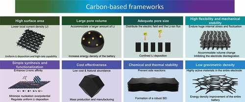
In practice, carbon-based materials show great potential as host frameworks for Li. This is owing to their low density and affordability, enabling low-cost manufacturing and packaging of high-energy-density batteries. Nevertheless, many challenges are yet to be solved and require intensive investigation and improvement. First, the large surface area offered by the carbon-based frameworks lowers the local current density, while it also maximizes the electrode/electrolyte interface area, which consequently forms a massive SEI layer. This results in undesirable consumption of the electrolyte. Secondly, the fundamentals behind the SEI formation require further understanding, because the SEI is consider one of the most important elements that affects the safety, power capability, and cycling and shelf life of the battery. In addition, the carbon host material needs to be compatible with the metallic current collector in terms of electrical conductivity to avoid direct Li deposition on the current collector. Furthermore, the need for higher energy density results in a greater demand to further lower the density of utilized carbon host at the anode. More importantly, the cost of the materials and processing of the carbon composites are relatively higher compared to other industry-based rechargeable batteries.
To deal with the aforementioned challenges, many key factors should be considered when utilizing carbon-based frameworks as a Li host material; First, the conductivity and lithiophilicity of the porous carbon are extremely essential parameters that can improve the deposition and nucleation behavior of the lithium metal, thus enhance the stability and prolong the lifespan of batteries. Moreover, further in-depth experimental and theoretical studies targeting the SEI formation mechanism are still needed, as the SEI layer plays an important role in mitigating further side-reactions between the electrolyte and the anode, as well as enabling uniform Li deposition by regulating the ion flux to the collector. Furthermore, it is required to develop an electrically, mechanically, and chemically stable and ultralight carbon nanocomposite frameworks with an appropriate surface area to pave the way towards a practical battery application.
Biographical note
Prof. Jung Ho Kim is a Professor at the Institute for Superconducting and Electronic Materials (ISEM), Australian Institute for Innovative Materials (AIIM), University of Wollongong, Australia. He received his Bachelor’s (1998), Master’s (2000), and PhD (2005) degrees from Sungkyunkwan University, Korea. His research is the rational design of materials for energy storage and harvesting applications.
Acknowledgments
This research was supported by the Technology Development Program to Solve Climate Changes through the National Research Foundation of Korea funded by the Ministry of Science, ICT (NRF-2021M1A2A2038145), Republic of Korea. This is also supported by the National Research Foundation (NRF-2020R1A2C1005852) of the Ministry of Science and ICT of Korea.
Disclosure statement
No potential conflict of interest was reported by the author(s).
Additional information
Funding
Notes on contributors

Hamzeh Qutaish
Hamzeh Qutaish is currently a PhD candidate in Prof. Jung Ho Kim’s group at Australian Institute for Innovative Materials (AIIM), University of Wollongong, Australia. He received his BSc (2011), MSc (2014) form Jordanian university of science and technology (JUST), Jordan. He received his M.Phil. (2019) from University of Wollongong. His research interest is focused on advanced materials for energy storage applications.

Min-Sik Park
Prof. Min-Sik Park is currently Associate Professor at Advanced Materials Engineering for Information and Electronics, Kyung Hee University, Republic of Korea. After his PhD at University of Wollongong, Australia (2008), he was a research scientist at Samsung Advanced Institute of Technology (SAIT) and Korea Electronics Technology Institute (KETI). His current research focuses on advanced materials for energy storage systems such as lithium-ion batteries and post-lithium systems for future energy solutions.

Jung Ho Kim
Prof. Jung Ho Kim is currently tenured Professor at Australian Institute for Innovative Materials (AIIM), University of Wollongong, Australia. He received his Bachelor’s (1998), Master’s (2000), and PhD (2005) degrees from Sung-kyunkwan University, Republic of Korea. His major research is the rational design of materials for energy storage and harvesting applications.
References
- Asl HY, Manthiram A. Toward sustainable batteries. Nat Sustainability. 2021;4(5):379–380
- Dell RM, Rand DAJ. Energy storage a key technology for global energy sustainability. J Power Sources. 2001;100(1–2):2–17.
- Hannan MA, Hoque MM, Mohamed A, et al. Review of energy storage systems for electric vehicle applications: issues and challenges. Renew Sust Energ Rev. 2017 march 01;69:771–789.
- Perumal P, Andersen SM, Nikoloski A, et al. Leading strategies and research advances for the restoration of graphite from expired Li+ energy storage devices. J Environ Chem Eng. 2021;9(6):106455.
- Mrozik W, Rajaeifar MA, Heidrich O, et al. Environmental impacts, pollution sources and pathways of spent lithium-ion batteries. Energy Environ Sci. 2021;14(12):6099–6121.
- Dunn B, Kamath H, Tarascon J-M. Electrical energy storage for the grid: a battery of choices. Science. 2011;334(6058):928–935.
- Wang Y, Zhang W, Chen L, et al. Quantitative description on structure–property relationships of Li-ion battery materials for high-throughput computations. Sci Technol Adv Mater. 2017;18(1):134–146.
- Ding Y, Cano ZP, Yu A, et al. Automotive Li-ion batteries: current status and future perspectives. Electrochem Energy Rev. 2019;2(1):1–28.
- Sun P, Bisschop R, Niu H, et al. A review of battery fires in electric vehicles. Fire Technol. 2020;6(4):1361–1410.
- Liu J, Gu T, Sun X, et al. Synthesis of MnO/C/Co3O4 nanocomposites by a Mn2+-oxidizing bacterium as a biotemplate for lithium-ion batteries. Sci Technol Adv Mater. 2021;22(1):429–440.
- Jehnichen P, Wedlich K, Korte C. Degradation of high-voltage cathodes for advanced lithium-ion batteries–differential capacity study on differently balanced cells. Sci Technol Adv Mater. 2019;20(1):1–9.
- Baik JM, Lee JP. Strategies for ultrahigh outputs generation in triboelectric energy harvesting technologies: from fundamentals to devices. Sci Technol Adv Mater. 2019;20(1):927–936.
- Kim JH. Focus on nanogenerators: toward smart wearable devices. Sci Technol Adv Mater. 2020;21(1):422–423.
- Han SA, Lee JH, Seung W, et al. Patchable and implantable 2D nanogenerator. Small. 2021;17(9):1903519.
- Hyeon Y, Lee J, Qutaish H, et al. Lithium metal storage in zeolitic imidazolate framework derived nanoarchitectures. Energy Storage Mater. 2020;33:95–107.
- Shin HR, Yun J, Eom GH, et al. Mechanistic and nanoarchitectonics insight into Li–host interactions in carbon hosts for reversible Li metal Storage. Nano Energy. 2022;95:106999.
- Ghazi ZA, Sun Z, Sun C, et al. Key aspects of lithium metal anodes for lithium metal batteries. Small. 2019;15(32):1900687.
- Pathak R, Chen K, Wu F, et al. Advanced strategies for the development of porous carbon as a Li host/current collector for lithium metal batteries. Energy Storage Mater. 2021;41:448–465.
- Kang J-H, Lee J, Jung J-W, et al. Lithium–air batteries: air-breathing challenges and perspective. ACS nano. 2020;14(11):14549–14578.
- Ye H, Zhang Y, Yin Y-X, et al. An outlook on low-volume-change lithium metal anodes for long-life batteries. ACS Cent Sci. 2020;6(5):661–671.
- Liu W, Liu P, Mitlin D. Tutorial review on structure–dendrite growth relations in metal battery anode supports. Chem Soc Rev. 2020;49(20):7284–7300.
- Zhang C, Huang Z, Lv W, et al. Carbon enables the practical use of lithium metal in a battery. Carbon. 2017;123:744–755.
- Zhang X, Wang A, Liu X, et al. Dendrites in lithium metal anodes: suppression, regulation, and elimination. Acc Chem Res. 2019;52(11):3223–3232.
- Wang J, Xu Y, Ding B, et al. Confined self‐assembly in two‐dimensional interlayer space: monolayered mesoporous carbon nanosheets with in‐plane orderly arranged mesopores and a highly graphitized framework. Angew Chem. 2018;57(11):2894–2898.
- Wang X-B, Jiang X-F, Bando Y. Blowing route towards advanced inorganic foams. Bull Chem Soc Jpn. 2019;92(1):245–263.
- Salunkhe RR, Tang J, Kamachi Y, et al. Asymmetric supercapacitors using 3D nanoporous carbon and cobalt oxide electrodes synthesized from a single metal–organic framework. ACS nano. 2015;9(6):6288–6296.
- Tang J, Salunkhe RR, Zhang H, et al. Bimetallic metal-organic frameworks for controlled catalytic graphitization of nanoporous carbons. Sci Rep. 2016;6(1):1–8.
- Lee J-H, Kim J, Kim TY, et al. All-in-one energy harvesting and storage devices?. J Mater Chem A. 2016;4(21):7983–7999.
- Salunkhe RR, Kaneti YV, Kim J, et al. Nanoarchitectures for metal–organic framework-derived nanoporous carbons toward supercapacitor applications. Acc Chem Res. 2016;49(12):2796–2806.
- Yan X, Lin L, Chen Q, et al. Multifunctional roles of carbon‐based hosts for Li‐metal anodes: a review carbon. Energy. 2021;230. 10.1016/j.energy.2021.120876.
- Liu Y, Li X, Fan L, et al. A review of carbon-based materials for safe lithium metal anodes. Front Chem. 2019;7:721.
- Tang K, Xiao J, Li X, et al. Advances of carbon-based materials for lithium metal anodes. Front Chem. 2020;7:931.
- Han W, Li Q, Zhu H, et al. Hierarchical porous graphene bubbles as host materials for advanced lithium sulfur battery cathode. Front Chem. 2021;9:171.
- Guan X, Wang A, Liu S, et al. Controlling nucleation in lithium metal anodes. Small. 2018;14(37):1801423.
- Li B, Wang Y, Yang S. A material perspective of rechargeable metallic lithium anodes. Adv Energy Mater. 2018;8(13):1702296.
- Guo Y, Li H, Zhai T. Reviving lithium‐metal anodes for next‐generation high‐energy batteries. Adv Mater. 2017;29(29):1700007.
- Li L, Li S, Lu Y. Suppression of dendritic lithium growth in lithium metal-based batteries. Chem Comm. 2018;54(50):6648–6661.
- Gao M, Li H, Xu L, et al. Lithium metal batteries for high energy density: fundamental electrochemistry and challenges. J Energy Chem. 2021;59:666–687.
- Vu TT, Kim BG, Kim JH, et al. Suppression of dendritic lithium-metal growth through concentrated dual-salt electrolyte and its accurate prediction?. J Mater Chem A. 2021;9(40):22833–22841.
- Xu W, Wang J, Ding F, et al. Lithium metal anodes for rechargeable batteries. Energy Environ Sci. 2014;7(2):513–537.
- Um JH, Yu SH. Unraveling the mechanisms of lithium metal plating/stripping via in situ/operando analytical techniques. Adv Energy Mater. 2021;11(27):2003004.
- Zhang J-G, Xu W, Henderson WA. Characterization and modeling of lithium dendrite growth. Lithium metal anodes and rechargeable lithium metal batteries. vol. 249. Switzerland: Springer International Publishing Cham; 2017.
- Hagopian A, Doublet M-L, Filhol J-S. Thermodynamic origin of dendrite growth in metal anode batteries. Energy Environ Sci. 2020;13(12):5186–5197.
- Han SA, Qutaish H, Park MS, et al. Strategic approaches to the dendritic growth and interfacial reaction of lithium metal anode. Chem–Asian J. 2021;16(24):4010–4017.
- Li Z, Huang J, Liaw BY, et al. A review of lithium deposition in lithium-ion and lithium metal secondary batteries. J Power Sources. 2014;254:168–182.
- Steiger J, Kramer D, Mönig R. Mechanisms of dendritic growth investigated by in situ light microscopy during electrodeposition and dissolution of lithium. J Power Sources. 2014;261:112–119.
- Brissot C, Rosso M, Chazalviel JN, et al. In situ concentration cartography in the neighborhood of dendrites growing in lithium/polymer‐electrolyte/lithium cells. J Electrochem Soc. 1999;146(12):4393.
- Brissot C, Rosso M, Chazalviel J-N, et al. Concentration measurements in lithium/polymer–electrolyte/lithium cells during cycling. J Power Sources. 2001;94(2):212–218.
- Brissot C, Rosso M, Chazalviel J-N, et al. Dendritic growth mechanisms in lithium/polymer cells. J Power Sources. 1999;81:925–929.
- Fleury V, Chazalviel J-N, Rosso M. Coupling of drift, diffusion, and electroconvection, in the vicinity of growing electrodeposits. Phys Rev E. 1993;48(2):1279.
- Rosso M, Gobron T, Brissot C, et al. Onset of dendritic growth in lithium/polymer cells. J Power Sources. 2001;97:804–806.
- Rosso M, Brissot C, Teyssot A, et al. Dendrite short-circuit and fuse effect on Li/polymer/Li cells. Electrochim Acta. 2006;51(25):5334–5340.
- Cheng J-H, Assegie AA, Huang C-J, et al. Visualization of lithium plating and stripping via in operando transmission X-ray microscopy. J Phys Chem C. 2017;121(14):7761–7766.
- Bai P, Guo J, Wang M, et al. Interactions between lithium growths and nanoporous ceramic separators. Joule. 2018;2(11):2434–2449.
- Choudhury S. The many shapes of lithium. Joule. 2018;2(11):2201–2203.
- Monroe C, Newman J. Dendrite growth in lithium/polymer systems: a propagation model for liquid electrolytes under galvanostatic conditions. J Electrochem Soc. 2003;150(10):A1377.
- Monroe C, Newman J. The effect of interfacial deformation on electrodeposition kinetics. J Electrochem Soc. 2004;151(6):A880.
- Ely DR, García RE. Heterogeneous nucleation and growth of lithium electrodeposits on negative electrodes. J Electrochem Soc. 2013;160(4):A662.
- Pei A, Zheng G, Shi F, et al. Nanoscale nucleation and growth of electrodeposited lithium metal. Nano Lett. 2017;17(2):1132–1139.
- Barai P, Higa K, Ngo AT, et al. Mechanical stress induced current focusing and fracture in grain boundaries. J Electrochem Soc. 2019;166(10):A1752.
- Aslam MK, Niu Y, Hussain T, et al. How to avoid dendrite formation in metal batteries: innovative strategies for dendrite suppression. Nano Energy. 2021;86:106142.
- Schweikert N, Hofmann A, Schulz M, et al. Suppressed lithium dendrite growth in lithium batteries using ionic liquid electrolytes: investigation by electrochemical impedance spectroscopy, scanning electron microscopy, and in situ 7Li nuclear magnetic resonance spectroscopy. J Power Sources. 2013;228:237–243.
- Cui J, Yao S, Ihsan‐Ul‐Haq M, et al. Correlation between Li plating behavior and surface characteristics of carbon matrix toward stable Li metal anodes. Adv Energy Mater. 2019;9(1):1802777.
- Zhang R, Cheng XB, Zhao CZ, et al. Conductive nanostructured scaffolds render low local current density to inhibit lithium dendrite growth. Adv Mater. 2016;28(11):2155–2162.
- Jiang R, Diao W, Xie D, et al. N-doped porous host with lithiophilic co nanoparticles implanted into 3D carbon nanotubes for dendrite-free lithium metal anodes. ACS Appl Energy Mater. 2021;4(11):12871–12881.
- Farha OK, Eryazici I, Jeong NC, et al. Metal–organic framework materials with ultrahigh surface areas: is the sky the limit? J Am Chem Soc. 2012;134(36):15016–15021.
- Qutaish H, Lee J, Hyeon Y, et al. Design of cobalt catalysed carbon nanotubes in bimetallic zeolitic imidazolate frameworks. Appl Surf Sci. 2021;547:149134.
- Liu Y, Xu X, Sadd M, et al. Insight into the critical role of exchange current density on electrodeposition behavior of lithium metal. Adv Sci. 2021;8(5):2003301.
- Tao R, Bi X, Li S, et al. Kinetics tuning the electrochemistry of lithium dendrites formation in lithium batteries through electrolytes. ACS Appl Mater Interfaces. 2017;9(8):7003–7008.
- Cheng Y, Chen J, Chen Y, et al. Lithium host: advanced architecture components for lithium metal anode. Energy Storage Mater. 2021;38:276–298.
- Jeong J, Chun J, Lim W-G, et al. Mesoporous carbon host material for stable lithium metal anode. Nanoscale. 2020;12(22):11818–11824.
- Zhang Y, Liu B, Hitz E, et al. A carbon-based 3D current collector with surface protection for Li metal anode. Nano Res. 2017;10(4):1356–1365.
- Geng H, Peng Y, Qu L, et al. Structure design and composition engineering of carbon‐based nanomaterials for lithium energy storage. Adv Energy Mater. 2020;10(10):1903030.
- Zheng G, Lee SW, Liang Z, et al. Interconnected hollow carbon nanospheres for stable lithium metal anodes. Nat Nanotechnol. 2014;9(8):618–623.
- Liu F, Xu R, Hu Z, et al. Regulating lithium nucleation via CNTs modifying carbon cloth film for stable Li metal anode. Small. 2019;15(5):1803734.
- Evers S, Nazar LF. New approaches for high energy density lithium–sulfur battery cathodes. Acc Chem Res. 2013;46(5):1135–1143.
- Kuang Y, Chen C, Kirsch D, et al. Thick electrode batteries: principles, opportunities, and challenges. Adv Energy Mater. 2019;9(33):1901457.
- Choi SH, Hyeon Y, Shin HR, et al. Critical role of surface craters for improving the reversibility of Li metal storage in porous carbon frameworks. Nano Energy. 2021;88:106243.
- Nanda S, Gupta A, Manthiram A. Anode‐free full cells: a pathway to high‐energy density lithium‐metal batteries. Adv Energy Mater. 2021;11(2):2000804.
- Li Y, Guo S. Material design and structure optimization for rechargeable lithium-sulfur batteries. Matter. 2021;4(4):1142–1188.
- Chi -S-S, Wang Q, Han B, et al. Lithiophilic Zn sites in porous CuZn alloy induced uniform Li nucleation and dendrite-free Li metal deposition. Nano Lett. 2020;20(4):2724–2732.
- Sun Z, Jin S, Jin H, et al. Robust expandable carbon nanotube scaffold for ultrahigh‐capacity lithium‐metal anodes. Adv Mater. 2018;30(32):1800884.
- Roberts AD, Li X, Zhang H. Porous carbon spheres and monoliths: morphology control, pore size tuning and their applications as Li-ion battery anode materials. Chem Soc Rev. 2014;43(13):4341–4356.
- Shen L, Shi P, Hao X, et al. Progress on lithium dendrite suppression strategies from the interior to exterior by hierarchical structure designs. Small. 2020;16(26):2000699.
- Lin D, Liu Y, Cui Y. Reviving the lithium metal anode for high-energy batteries. Nat Nanotechnol. 2017;12(3):194–206.
- Zhang Y, Zuo -T-T, Popovic J, et al. Towards better Li metal anodes: challenges and strategies. Mater Today. 2020;33:56–74.
- Jiang H, Dong Q, Bai M, et al. A 3D-mixed ion/electron conducting scaffold prepared by in situ conversion for long-life lithium metal anodes. Nanoscale. 2021;13(5):3144–3152.
- Yun J, Park B-K, Won E-S, et al. Bottom-up lithium growth triggered by interfacial activity gradient on porous framework for lithium-metal anode. ACS Energy Lett. 2020;5(10):3108–3114.
- Park KH, Kang DW, Park J-W, et al. Modulating the electrical conductivity of a graphene oxide-coated 3D framework for guiding bottom-up lithium growth?. J Mater Chem A. 2021;9(3):1822–1834.
- Lee J, Park M-S, Kim JH. Stabilizing Li-metal host anode with LiF-rich solid electrolyte interphase. Nano Convergence. 2021;8(1):1–8.
- Chen X, Chen X-R, Hou T-Z, et al. Lithiophilicity chemistry of heteroatom-doped carbon to guide uniform lithium nucleation in lithium metal anodes. Sci Adv. 2019;5(2):eaau7728.
- Tarascon JM, Armand M. Issues and challenges facing rechargeable lithium batteries. Nature. 2001 november 01;414(6861):359–367.
- Cheng X-B, Zhang R, Zhao C-Z, et al. Toward safe lithium metal anode in rechargeable batteries: a review. Chem Rev. 2017 august 09;117(15):10403–10473.
- Biswal P, Stalin S, Kludze A, et al. Nucleation and early stage growth of Li electrodeposits. Nano Lett. 2019 november 13;19(11):8191–8200.
- Zuo -T-T, X-w W, Yang C-P, et al. Graphitized carbon fibers as multifunctional 3D current collectors for high areal capacity Li anodes. Adv Mater. 2017;29(29):1700389.
- Niu C, Pan H, Xu W, et al. Self-smoothing anode for achieving high-energy lithium metal batteries under realistic conditions. Nat Nanotechnol. 2019 june 01;14(6):594–601.
- Liu K, Li Z, Xie W, et al. Oxygen-rich carbon nanotube networks for enhanced lithium metal anode. Energy Storage Mater. 2018 november 01;15:308–314.
- Li N, Zhang K, Xie K, et al. Reduced-graphene-oxide-guided directional growth of planar lithium layers. Adv Mater. 2020;32(7):1907079.
- Zhang R, Chen X-R, Chen X, et al. Lithiophilic sites in doped graphene guide uniform lithium nucleation for dendrite-free lithium metal anodes. Angew Chem. 2017;129(27):7872–7876.
- Liu H, Chen X, Cheng X-B, et al. Uniform lithium nucleation guided by atomically dispersed lithiophilic conx sites for safe lithium metal batteries. Small Methods. 2019;3(9):1800354.
- Liu L, Yin Y-X, J-y L, et al. Uniform lithium nucleation/growth induced by lightweight nitrogen-doped graphitic carbon foams for high-performance lithium metal anodes. Adv Mater. 2018;30(10):1706216.
- Kim J, Lee J, Yun J, et al. Functionality of dual-phase lithium storage in a porous carbon host for lithium-metal anode. Adv Funct Mater. 2020;30(15):1910538.
- Lee J, Choi SH, Qutaish H, et al. Structurally stabilized lithium-metal anode via surface chemistry engineering. Energy Storage Mater. 2021 may 01;37:315–324.
- Yang C, Yao Y, He S, et al. Ultrafine silver nanoparticles for seeded lithium deposition toward stable lithium metal anode. Adv Mater. 2017;29(38):1702714.
- Yan J, Liu M, Deng N, et al. Flexible MnO nanoparticle-anchored N-doped porous carbon nanofiber interlayers for superior performance lithium metal anodes. Nanoscale Adv. 2021;3(4):1136–1147.
- Yang G, Li Y, Tong Y, et al. Lithium plating and stripping on carbon nanotube sponge. Nano Lett. 2019 january 09;19(1):494–499.
- Li X, Chu Z, Jiang H, et al. Redistributing Li-ion flux and homogenizing Li-metal growth by N-doped hierarchically porous membranes for dendrite-free lithium metal batteries. Energy Storage Mater. 2021 may 01;37:233–242.
- Yan K, Lu Z, Lee H-W, et al. Selective deposition and stable encapsulation of lithium through heterogeneous seeded growth. Nature Energy. 2016 february 22;1(3):16010.
- Fang Y, Zhang SL, Z-p W, et al. A highly stable lithium metal anode enabled by Ag nanoparticle–embedded nitrogen-doped carbon macroporous fibers. Sci Adv. 2021;7(21):eabg3626.
- Jin C, Sheng O, Luo J, et al. 3D lithium metal embedded within lithiophilic porous matrix for stable lithium metal batteries. Nano Energy. 2017 july 01;37:177–186.