
 ?Mathematical formulae have been encoded as MathML and are displayed in this HTML version using MathJax in order to improve their display. Uncheck the box to turn MathJax off. This feature requires Javascript. Click on a formula to zoom.
Abstract
Global research programs seeking to achieve a commercially viable model of a fusion power plant are being accelerated at an unprecedented rate. One critical element to the design and licensing is an accurate understanding of the radiation environment throughout the plant lifetime and subsequent decommissioning phase. The radiation field, which results from the nuclear fusion reaction, gives rise to highly complex phenomena such as flux leakage, materials activation, and decay gamma fields. Demonstration of compliance with limits, the integrity of components, and the permissibility of operations are all fundamental to regulatory approval and the overall safety of a nuclear device. As such, neutronics, which is used in the general sense to refer to the mapping of radiation fields in nuclear devices, is a critical design driver. The Applied Radiation Technology group at the United Kingdom Atomic Energy Authority is a world leader in this field, developing new methods and deploying state-of-the-art codes to conduct nuclear analysis. As well as applied neutronics in areas spanning fusion reactors, medical applications, spallation neutron sources, and nuclear fission, there is an extensive parallel experimental program undertaking critical radiation field characterization and conducting measurements using an array of bespoke particle detection systems. This paper highlights recent technical developments made by this group in the context of outstanding challenges in this field, as well as providing an overview of current methods and capabilities for the broader interest of the community.
I. INTRODUCTION
There is a clear heightened investment both at the government level and privately to expedite the pathway to commercial fusion energy as a means for generating safe, sustainable, and low-carbon electricity. The United Kingdom has launched its own ambitious program to develop a prototype Spherical Tokamak for Energy ProductionCitation1 (STEP) by 2040. A concerted research and development effort focused on developing a conceptual design was launched in 2019 at the United Kingdom Atomic Energy Authority (UKAEA) with an initial £220 million government grant. STEP is a first-of-a-kind large-scale engineering project with many unique, multifaceted challenges. To address outstanding physics and engineering gaps, innovative solutions capable of scaling to a plant level will be required. Fundamental to this is the integration across different disciplines, such as plasma physics, mechanical engineering, structural engineering, and neutronics, such that the iterative pathway to a plant solution is performed holistically. The interface between these different areas and their unique constraints requires the development of codes that can be tightly coupled and converged to a solution over the timescales that are needed as input to subsequent iterations of a design.
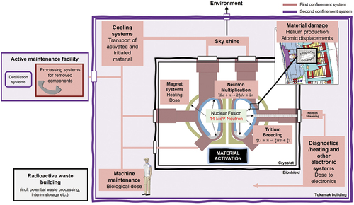
As fusion enters the delivery phase, accurate characterization of the nuclear environment is a key input to the demonstration of nuclear safety. The favored deuterium-tritium nuclear fusion reaction gives rise to 14-MeV neutrons that go on to interact with the materials in the reactor through diverse complex phenomena, such as flux leakage, materials activation, and decay gamma fields (see ). Systems codes, including BLUEMIRA (CitationRefs. 2, Citation3, and Citation4), developed in collaboration between EUROfusion and the UKAEA, integrate different physics and engineering modules as a design tool for future fusion reactors. One of the core inputs is neutronics, the study of the behavior of neutrons, and more broadly, the radiation environment. Integration with systems codes stipulate that the neutronics assessments must be performed on rapid timescales. With current methods and available computing infrastructure, this is feasible for scoping studies based largely on homogenized geometry representations.
Fig. 1. Schematic illustration of the complex nuclear environment in an operating fusion tokamak. The diagram describes only some of the many complex phenomena that arise from the fusion reaction.
Fusion neutronics is arguably one of the most demanding fields for Monte Carlo codes, which are most commonly applied and indeed developed for the domain of fission reactor physics calculations. Beyond systems codes, the engineering-level design model must determine the nuclear responses at sufficient spatial resolution, extracted from a geometry that captures the modeled system in all its complexity. The current most practiced workflow involves a multistep process calling proprietary software, with several bottlenecks, most notably in the preparation of a computer-aided design (CAD) geometry that is suitable for radiation transport analyses. The current limitations and immediate analysis needs channel current software developments and also serve to motivate the exploration of alternative workflows. Emergent radiation transport codes such as OpenMC (CitationRef. 5) and SerpentCitation6 are now at a level of maturity that permits application to most fusion modeling problems, subject to further validation.
The Applied Radiation Technology (ART) Group at the UKAEA is driving the nuclear design of fusion power reactors through analysis of the radiation environment and validation through measurement. In this paper, we present specific examples from a broad portfolio of research to highlight recent advances in this field. To increase the efficiency of the workflow, a series of CAD-based tools have been developed (Sec. II.B) using an application programming interface (API) for ANSYS SpaceClaim. For the determination of decay gamma fields, a Novel-1-Step (N1S) method (Sec. II.C) is detailed, providing an accurate, single-step method that overcomes some of the key drawbacks of current approaches. The UKAEA is also actively benchmarking different particle transport codes (Sec. II.D), as well as the application of these modern workflows in the analysis of STEP, and an example of their validation is presented. Efforts to advance multiphysics approaches for activated fluids in a fusion reactor are presented in Sec. II.E. The experimental division of ART includes the onsite radiometric laboratory, termed the Radiological Assay and Detection Laboratory (RADLab), which hosts a wide array of particle diagnostic systems. In the scope of immediate experimental needs in fusion, the development of a passive neutron spectrometry (PNS) system for future characterization of neutron spectra in low-dose environments is highlighted in Sec. III.B.
II. APPLICATION AND DEVELOPMENT OF NUCLEAR MODELING
II.A. Analysis Workflow
The conventional method most widely adopted today for performing nuclear analysis of fusion reactors is outlined in . The codes included in the figure are specific to the workflow employed at the UKAEA. In the first stage, a CAD model is received at an engineering level of detail. To derive a neutronics model, the CAD model is simplified such that it retains only transport-relevant features, i.e., those that will have a nonnegligible impact on the nuclear response being studied. This typically involves the removal of interferences and small features, such as rounds and bolts. Complex surface types, such as splines and tori, as well as other higher-order surfaces must also be simplified (typically by redrawing). Due to the abundance of inherent software features that aid in the simplification process, ANSYS SpaceClaim has been the adopted CAD platform for this purpose since circa 2011. The approximations introduced at this stage are typically quantified by volumetric comparison with the original file. There is inevitably some immediate differences to the model adopted in other engineering analyses. Conversion to a constructive solid geometry (CSG) format is performed using conversion software such as SuperMC (CitationRef. 7) or McCad (CitationRef. 8). The CAD model preparation preceding this stage, together with the conversion process and subsequent validation of a geometrically “clean” model, can account for over 50% of the entire workflow.
Fig. 2. Schematic overview of the conventional workflow including computational tools used for radiation transport analysis at the UKAEA.
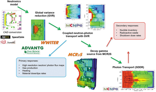
Transport calculations using the Monte Carlo code MCNP (CitationRef. 9) often require variance reduction techniques to reduce the stochastic uncertainty in deep shielded regions, which is generally any response external to the inner surface of the vacuum vessel in tokamaks. ADVANTG (CitationRef. 10) software is capable of automatically generating the variance reduction parameters for one such method, weight windows, in both the global and local scheme. The UKAEA developed an alternative methodology based on iteratively populating the geometry to derive weight window bounds. This method, WWITER (CitationRef. 11), has been demonstrated for JET, ITER, and DEMO applications.Citation12–14
To evaluate the shutdown dose rate at different decay times, the UKAEA uses its own mesh-coupled rigorous two-step (MCR2S) code.Citation15 As further detailed in Sec. II.C, this is one of several methods for this purpose. MCR2S couples an on-load neutron transport calculation with an inventory calculation performed using an external activation solver, FISPACT-II (CitationRef. 16), which was developed and is maintained at the UKAEA. FISPACT-II is capable of predicting the time evolution of a material composition under irradiation. The release of FISPACT-II v5.0 in January 2022, available through the Radiation Safety Information Computational Center and the Nuclear Energy Agency, includes an API to increase its functionality and allow efficient coupling to other codes. A Python-based utility for parsing FISPACT output files, “pypact,”Citation17 is also now openly available.
II.B. SpaceClaim API Tool Development
To mitigate bottlenecks in the preparation of “conversion-ready” CAD geometry, the UKAEA has developed a suite of tools that utilize the API available in SpaceClaim. Tools have been written both in C# and Python and integrated together through C#, such that they are directly accessible as part of the SpaceClaim Ribbon ().
Fig. 3. List of SpaceClaim tools developed at the UKAEA using the SpaceClaim API directly accessible in the application ribbon.
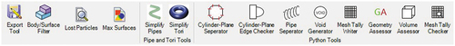
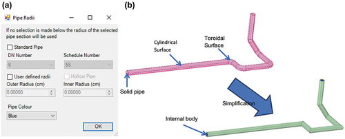
The tool suite is open sourceCitation18 with accompanying user documentation detailing installation and guidance for use of each tool. The tools provide either direct automation of more arduous modeling tasks or equip the analyst with additional data to reduce the time spent identifying problematic geometry regions. One example tool is the pipe simplification tool, which can be used to convert a given complex pipe network to a series of cylinders that are suitable for conversion. The internal fluid/void volume is also optionally created. An example is shown in , along with the user interface that allows specification of pipe thickness based on a user-defined input or hard-coded American Society of Mechanical Engineers–basedCitation19 pipe standards. The option to add color to the geometry facilitates the distinction of different materials, which streamlines their assignment in the CSG model. The time to simplify a single pipe network is reduced from several minutes to a few seconds. For a geometry as vast as the ITER tokamak cooling water system, which consists of tens of kilometers of cooling water, this tool greatly reduced the modeling effort, which ultimately shifted the emphasis to the more significant analysis of nuclear responses. An example of this application for SpaceClaim API tools is given in CitationRef. 20.
Fig. 4. User interface for the (a) pipe simplification tool together with an example of the (b) original and simplified pipe geometry.
Further tools have since been developed at Fusion for EnergyCitation21 (F4E) that are more tailored toward specific manipulation of the geometry for MCNP once it has been simplified. There is scope to harness the API for other engineering applications that are embedded in the ANSYS suite. The simplification process means that the neutronics model can differ greatly from that used in engineering simulation. Coupling methods, which may leverage the API, would minimize this disparity through an intermediary model that can be adopted, for example, in high-fidelity finite element analysis while being sufficiently lightweight to perform particle transport.Footnotea
II.C. Development of a New Method for Shutdown Dose Rate Calculations
The MCR2S method used by the UKAEA in the evaluation of shutdown dose rates has several inherent approximations. The method is based on calculating the neutron spectra on a mesh, which at the voxel level implies a degree of flux averaging both spatially and in energy. Further, the method is in reality more like a three-step process consisting of a neutron transport simulation, inventory calculation, and a final photon transport calculation. The other method used widely for evaluating fusion shutdown dose rates is the Direct 1-Step methodCitation22–24 (D1S). Rather than discretizing the problem space to derive neutron spectra, the exact position of each activation reaction is retained and the neutron and decay photon transport performed in a single Monte Carlo simulation. This is implemented through the substitution of neutron-induced prompt photons with decay photons using dedicated cross-section libraries. This method relies on a priori knowledge of the important reactions to the dose response and the evaluation of time correction factors for each important isotope that link their activity and production rate to the irradiation schedule and decay times of interest. This information typically requires the use of an external activation calculation using an inventory code such as FISPACT-II.
The limitations of each method motivated the development of a N1S methodCitation25 to determine the response at decay times of interest in a single transport calculation. The need for an external activation solver is removed by including the irradiation scenario as a time-dependent neutron source term. Activation reactions occurring in neutron transport are evaluated explicitly at the location at which they occur, with all the information on decay chains captured in a specially developed decay library. Full accountancy is made for self-shielding effects in materials. Each of the decay photons is assigned a weight that is essentially a probability of the decay happening at the decay times of interest specified by the analyst. The photon transport is performed in the same calculation as the neutron transport and the weights used to modify the calculated dose rates at each decay time. A flowchart of the N1S methodology is shown in . Currently, the N1S method is implemented for MCNP and has been validated using the ITER computational port plug benchmarkCitation26 and the Frascati Neutron Generator (FNG) ITER Shutdown Dose Rate benchmarkCitation27 (see CitationRef. 25 for more details).
Fig. 5. Flowchart describing the workflow implemented for the N1S method for determining shutdown dose rates.
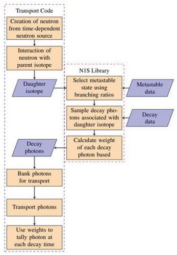
When compared to the R2S method, the total time to evaluate dose rates is significantly shorter. The single transport calculation is more computationally expensive (effectively equivalent to a coupled neutron-photon calculation), however no intermediate steps are needed by the analyst. The code has been developed with the prerequisite to be portable to different transport codes. At present, N1S has been implemented for MCNP, however, there is ongoing work to enable OpenMC to be used. Future effort is focused on accounting for the modification of the geometry during shutdown, such as the removal of components or draining of fluids. The time dependence of the neutron source included in the neutron transport calculation gives scope to account for the time evolution of material compositions as a function of time, which is not currently considered in existing methods. All of the previously mentioned inherent capabilities and efficiency improvements over existing methods make N1S well suited to the parametric reactor design and/or integration with multiphysics work streams.
II.D. Benchmarking of Radiation Transport Codes
The use of the Monte Carlo method has long been the accepted practice for radiation transport analysis of fusion devices. MCNP, a Monte Carlo code developed at Los Alamos National Laboratory, is to date the most widely adopted code in the fusion neutronics community. The growing capability of alternative transport codes, such as Serpent 2 and OpenMC, in recent years has led to the investigation of their potential for this application. Benchmarking efforts that have been conducted at the UKAEA can be found in CitationRefs. 28 through 33.
Validation of the accuracy of a transport code is fundamental when they are being deployed in fusion reactor analysis. The implications of nuclear analysis span practically all aspects of the reactor from maintenance schedules to plant economics. STEP is in a conceptual design phase with a 200+ team at the UKAEA developing a viable design point for a reactor to be commissioned within the next 2 decades. The complex interfaces between multiple different systems and their individual requirements gives a broad design space that must be explored in an iterative manner to find the optimal solution for the plant. The workflow described in is not an efficient means for conducting scoping studies across multiple different design proposals. The workflow currently being used for STEP uses OpenMC with the geometry driven by parametric codes that can be automated.
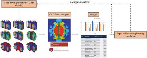
DAGMC (CitationRef. 34) is a toolkit that allows for transporting particles directly on the CAD geometry based on a surface-faceted representation. It can interface with several particle transport codes, including OpenMC. Using the parametric workflow and harnessing direct tracking on CAD through DAG-OpenMC, a simple calculation of the tritium breeding ratio (TBR) without variance reduction can be completed in 20 to 30s on 64 CPU cores. A broad design space can be quickly assessed through modifying variables, and the open-source nature of OpenMC allows deployability on any high-performance computing infrastructure without licensing restrictions. The workflow (see ) has been used to date in assessments of nuclear heating, TBRs, and neutron flux profiles. The output from the nuclear analysis is then available for other physics/engineering studies on a practical timescale, streamlining the entire design evolution process.
Fig. 6. Schematic overview of the workflow for nuclear analysis based on parameter-driven CAD models and CAD-based particle transport. The reactor CAD models in the illustration are output using the Paramak, one example of a framework developed at UKAEA for parametrically generating 3D CAD models.Citation36 CAD models © 2021 J. Shimwell et al. under an Open Access CC-BY license.
The uptake of emergent radiation transport codes as alternatives to MCNP has only been possible with conformance to a key set of code requirements for this application. These are outlined in detail in CitationRef. 35. One of these is the capability to converge solutions to a sufficient level of statistical accuracy in deep shielded regions. These so called variance reduction methods are generally needed for studies external to the vacuum vessel. Current tools developed for MCNP were given in Sec. II.A. Weight windows are one of the commonly adopted variance reduction techniques that artificially bias the simulation through increasing particle populations in the region of interest and correcting for this by accordingly adjusting a parameter assigned to each particle called its weight. Where responses are calculated, it is the sum of particle weights that is evaluated.
In 2019, Serpent developed a capability to automate the generation of the parameters controlling the bounds of the weight window,Citation37 which has been benchmarked for several fusion-relevant problems.Citation28,Citation33 In February 2022, OpenMC 0.13.0 was released with the capability to read weight window files. At present, we have added two different approaches for generating weight windows. The first gives the capability to convert Cartesian meshes populated in an analogue calculation to weight windows with the bounds iteratively adjusted to populate deeper shielded geometry regions. This is the MAGIC method,Citation11 which is the basis for the WWITER tool. The second method, known as Pseduo-Source Global Variance ReductionCitation38 (PS-GVR), also allows conversion of analog-populated meshes to weight windows, but does so in such a way that splitting is heavily reduced in mesh cells that score high enough fluxes to give acceptable statistics. The primary advantage of this method is that run times are improved, versus the MAGIC method, while maintaining a similar level of improvement in the stochastic uncertainties. The automated generation of weight window boundaries will remove much of the onus on the user to optimize the weight window; at the time of writing, this is currently under development.
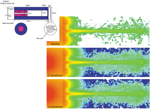
Preliminary testing of this capability has been performed using the ITER port plug benchmark. The geometry consists of an outer steel cylinder with an inner steel/water mix cylinder containing a small radius streaming channel. At the rear of the port plug mockup is a 15-cm-thick steel closure plate. The source is a 14-MeV cylindrical source with isotropic emission, 10 cm from the front face of the port plug geometry. The PS-GVR–based weight window scheme was used to globally increase the particle population density in a 5 5
5-cm
mesh. Demonstration of this is given in for 10
source particles. It was observed that a larger proportion of voxels were populated with reduced statistical error relative to the analog simulation. There is negligible improvement for this particular geometry beyond two iterations.
Fig. 7. Neutron flux map for the ITER port plug benchmark in OpenMC using an iterative scheme to generate global weight windows with increasing convergence across the entire mesh. The weight window boundaries are generated with the PS-GVR method.
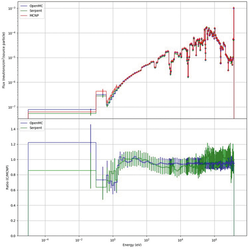
A comparison was made to a Serpent model of the benchmark using its built-in response matrix method–based importance solver for generating weight windows. Both of the Serpent and OpenMC geometries were converted from the MCNP input file using the UKAEA-developed csg2csg (CitationRef. 39) code. The neutron spectra were determined in 175 energy groups (VITAMIN-J) in the plate at the rear of the port plug. The spectra were also determined in MCNP using a weight window generated in ADVANTG. shows excellent agreement between each of the codes with a minor discrepancy at lower energies where the statistical error is higher. For deep shielding problems, both Serpent and OpenMC would benefit from the addition of further statistical tests, such as the the “ten statistical tests” implemented in MCNP.
Fig. 8. Comparison of the MCNP-, Serpent-, and OpenMC-calculated neutron spectra in the closure plate of the ITER computational port plug. Each code uses an independent method of variance reduction (PS-GVR, ADVANTG, and response matrix method–based importance solver).
The addition of this capability in OpenMC and its validation is fundamental to the continued adoption of the code for nuclear analysis of STEP. Nuclear responses can be studied in ex-vessel regions where, for example, the shutdown dose rate could be determined using the N1S-OpenMC method (see Sec. II.C). Further testing is required with more advanced geometries, an extreme case of which is the ITER reference model for nuclear analysis, which has been successfully converted and demonstrated for transport particles in OpenMC (CitationRef. 28).
II.E. Modeling of Activated Fluids in Fusion Reactors
During fusion operations, a significant volume of fluid will pass through in-vessel components, including coolant, and possibly, liquid breeder material. The ITER Test Blanket Module Program is investigating several different blanket concepts seeking to optimize tritium breeding with technological feasibility. Lithium-lead (LiPb) is one example of a liquid metal breeder material in several of the currently explored concepts. Flowing water is used as a coolant in certain blanket concepts, as well as more widely across ITER components to extract excess heat. In the presence of a neutron field, water is activated through (n,p) reactions with isotopes of oxygen, O. The most notable product is
N, which decays through emission of 6.13-MeV (I = 67%) and 7.12-MeV (I = 5%) (CitationRef. 40) photons. There is an additional gamma source term in the fluid that stems from activated corrosion products, along with secondary neutron emission from the decay of
N. Other potential coolants in future fusion devices include molten metals and salts, which would introduce different activation and corrosion profiles. The movement of activated fluids through the tokamak complex has significant implications for the demonstration of safety.
The UKAEA has developed two codes for modeling the transport of activated fluids: GammaFlowCitation41 and ActiFlow.Citation42 ActiFlow calls the FISPACT-II inventory code to simulate the irradiation of a material in a path through mesh- and cell-based fluxes. GammaFlow uses a cell-based approach, relying on user-input reaction rates and decay rates to model the evolution of particular nuclides using a dedicated API. GammaFlow is well suited to simple materials in well-defined flow paths, providing computationally inexpensive analysis scalable to the complex pipe networks anticipated in ITER and DEMO. ActiFlow is well suited to more demanding activation analysis (such as for LiPb) without requiring detailed knowledge of fluid volumes. Both codes can account for splitting of flow paths and residence time distributions, such as in fluid delay tanks (allowing for decay).
One aim of fluid activation analysis is the coupling of the neutron transport simulation with computational fluid dynamics (CFD) in order to capture the dynamics of fluid flow through a system. Originally, both codes ignored fluid dynamics effects, assuming a uniform velocity profile such that the residence time in a circuit component is proportional to the fluid volume. The assumption holds reasonably well for turbulent flow, but is less accurate for laminar flow conditions. The open-source CFD software OpenFoamCitation43 has been used to provide input on the velocity profiles to ActiFlow and GammaFlow. This was benchmarked against the ITER first-wall mockup water activation experiment performed with the FNG source in 2019 (CitationRef. 44). A clear improvement of 13% for the lowest predicted calculated to experiment ratio has been observed when accounting for the fluid effects, with good agreement between the codes.Citation42 Further work is needed to more rigorously couple the codes with CFD calculations, such as implemented by F4E (CitationRef. 45), with continuing benchmarking activities including the design of a water activation loop at the TRIGA reactor.Citation46 The advancement of this multiphysics approach is a key undertaking for integrated power plant design.
III. EXPERIMENTAL ACTIVITIES
III.A. Capability and Expansion of Radiometric Activity at the UKAEA
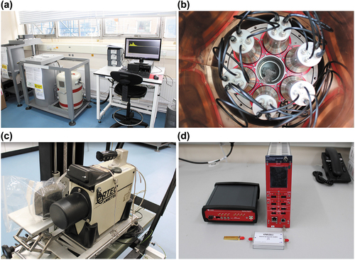
The UKAEA hosts a significant portion of the Advanced Digital Radiometric Instrumentation for Applied Nuclear Activities (ADRIANA) instrument suite (see ) as part of the UK National Nuclear User Facility.Footnoteb This includes an array of particle detection systems, including a broad energy germanium (BEGe) detector with a Compton suppression coincidence veto system, a high relative efficiency high-purity germanium (HPGe) detector, and a Trans-SPEC portable HPGe detector. Some examples of the broad portfolio of work conducted with this equipment includes waste assay measurements, diagnostics for JET and MAST, material characterization for the UKAEA’s Materials Research Facility, and provision of radiometric support for private fusion companies. A brand new laboratory will be occupied in 2022 allowing significant expansion of equipment and onsite capabilities. The existing technologies in the ADRIANA suite at Culham will be consumed into this laboratory, termed the RADLab.
Fig. 9. (a) BEGe and data acquisition setup in the current onsite lab, (b) close-up view of the associated Compton suppression system with several sodium iodide detectors, (c) portable Trans-SPEC HPGe, and (d) diamond detector with data acquisition system.
Extensive work supporting European Union (EU) collaborative activities through gamma spectrometry, such as activation studies of ITER materials through the neutron production at JET, have been undertaken at the laboratory,Citation47–49 with analysis also contributed through participating EU laboratories in Italy, Greece, and Poland. Underpinning activation nuclear data validation activities have included the use of and data derived from 14-MeV neutron irradiation facilities such as ASP, based in the United Kingdom, and the Fusion Neutronics Source, which was based in Japan.Citation50–53 Support for a range of EU experimental activities at the FNG have also been conducted, see for example, CitationRefs. 54, Citation55, and Citation56.
One example of a planned future experiment is to develop an inboard shielding mockup experiment to mitigate the risk within compact device-shielding designs, where shielding space is at a premium for the protection of sensitive components such as superconducting magnets. The status of the experiment is in the design process with plans to perform the experiment at a well-characterized 14-MeV neutron irradiation facility expected in 2024.
The UKAEA has procured diamond detectors, activation foils, and thermoluminescent dosimeters (TLDs) for the detection of fast and thermal neutrons and gammas in this experiment. This will validate and drive the design of shielding concepts as needed in the high-flux environments of future fusion devices, such as STEP. It will also provide additional valuable data for the validation of simulation methods, some of which were discussed in preceding sections. The diamond detectors as well as other high specification instrumentation that are part of the UKAEA radiometric laboratory have applications spanning fusion and fission power plants, nuclear security, decommissioning, university projects, and other research areas.
III.B. Novel System for Understanding Operational Fields
The measurement of neutron spectra provides a key understanding of the radiation environment and is an important diagnostic for fusion devices. A broad review of modern neutron detection was undertaken and publishedFootnotec
in 2020 with fusion-oriented technology contributions, see for example, CitationRefs. 57 and Citation58. Further contributions toward resilient neutron detection instruments and neutron spectrum unfoldingCitation59 aimed toward power plant environments and for pulsed neutron fieldsCitation60 have also been researched. Under this theme, a fusion-relevant PNS system has been designed from first principles and manufactured at the UKAEA. This consists of a 30-cm diameter high-density polyethylene (HDPE) sphere with as series of TLD badges used to measure dose. The TLDs are located along arms through the sphere in pairs comprising TLD-600 (96% Li) and TLD-700 (96%
Li) badges. The system is highly portable, and unlike active methods of characterization, does not require any electronics or active monitoring.
The design process utilized the Python package, SPECTRA-UF (CitationRef. 61), which was developed by the UKAEA to create a unified package for automating the unfolding process. To generate response matrices in the TLDs, a Python script was developed to automatically generate MCNP geometry and perform a neutron transport simulation with the dose tallied in each dosimetry disk position. To optimize the TLD locations, a synthetic data set together with the SPECTRA-UF code was utilized. A flat a priori spectrum was used as the initial guess in this case. The spectra were compared to those determined at several low-dose locations in MAST and JET, which were derived using transport simulations with the respective MCNP models. The more empirical data gathered increases the population of the response matrix, and therefore the fidelity of the spectrum (in energy) that can be unfolded. With the increasing size of the sphere, it was found that diminishing returns are observed above a 30-cm diameter. At this diameter, different arm structures as well as the number of TLD badges per arm were also studied. A configuration with 14 arms (through seven axis) with six TLD pairs per arm was derived as the final design, as illustrated in .
Fig. 10. (a) CAD model and (b) manufactured model of PNS detector with a 30-cm-radius sphere of HDPE, 14 arms each with six pairs of TLD-600 and TLD-700 badges equally spaced along each arm. In (b), the TLD reader can be seen in the background.
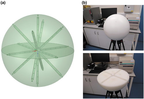
The fabrication of the PNS was completed by the Manufacturing Support Group at the UKAEA using a specialized computerized numerical control machine. First irradiation will take place in 2022 before being deployed in either a MAST-U or JET campaign as a proof of concept and demonstration of its suitability for deployment in STEP, ITER, and DEMO. As well as aiding the understanding of the neutron spectra during early operations of these future devices, the data will also be valuable for the validation of simulation methods prior to full-power operations.
IV. CONCLUSION
Demonstration of a commercially viable pathway to fusion energy will require novel, innovative solutions in order to address outstanding scientific and engineering gaps in present day understanding. Neutronics is the area of research concerned with the characterization of the radiation field, which impacts almost all aspects of a fusion plant. A complete understanding of the radiation environment through demonstration of the as-low-as-reasonably-achievable principle is needed to ensure the safe and controlled operation of a fusion power plant. The codes and methods that are driving forward the design should be rigorously validated and fully capable of accurately calculating nuclear responses at a sufficient level of fidelity on the timescales required.
The UKAEA has advanced and is extending its capability to perform radiation analysis and validation through measurement. The organization has a focused research and development effort to accelerate nuclear design and address outstanding challenges where they exist in current neutronics practices. In this paper, examples of developments that increase the efficiency of the applied analysis workflow have been outlined. The set of tools integrated into SpaceClaim using the API significantly reduce the time needed to perform certain geometry simplification tasks. The development of a N1S method combines advantages of the existing R2S and D1S methods. Using a time-dependent source term together with a specially prepared nuclear data library, the shutdown dose rate at different cooling times is evaluated in a single transport calculation. This method reduces the time needed for the computation of dose rates and has been developed to allow interfacing with different transport codes. One outstanding development gap is in the accurate modeling of activated fluids and their transport through a system, specifically activated corrosion products. The UKAEA has developed two codes that look to couple fluid activation with the dynamics of its flow, providing a framework to develop further capabilities, such as the addition of phenomena like corrosion.
The existing conventional workflow, which uses MCNP for particle transport, has been extensively applied across a multitude of fusion problems, including JET, MAST, ITER, DEMO, and others. Both OpenMC and Serpent Monte Carlo codes are being explored as potential complementary codes to MCNP. In the conceptual design phase of STEP, a new workflow has been devised based on the code-driven generation of CAD models and particle transport on the CAD geometry using DAG-OpenMC. This allows for scoping a broad design space on timescales of the order of minutes to hours depending on model complexity. With the development of new simulation tools and methods and their deployment in shaping the design of future reactors, validation is a critical underpinning that, at some stage, will fall under the scrutiny of the nuclear regulator. A benchmark case adopting the ITER port plug geometry was used as validation for a recently implemented variance reduction capability in OpenMC. This was compared to both Serpent and MCNP using independently generated weight windows, with excellent agreement observed in the neutron spectra for a cell at the rear of the port plug.
Future planned experiments will provide vital experimental data. An inboard shielding mockup experiment is being designed in order to better understand the effectiveness of potential shielding materials in the harsh environment that plasma-facing components are exposed to. As well as valuable data for code validation, this will provide crucial input for developing the most optimal shield of critical in-vessel components in devices like STEP. A fusion-relevant PNS system for the characterization of neutron spectra in operational environments has also been detailed. This provides a highly portable and flexible system that does not require active electronics, giving many advantages over current limited methods for characterizing the neutron field. The system has now been manufactured at the UKAEA and will undergo irradiation in late 2022 for preliminary testing prior to deployment in MAST-U and JET.
The design, procurement of detectors, and analysis of the inboard shielding mockup and PNS system are examples of ongoing world-leading research in the sphere of fusion radiometrics. More broadly, the ART group will occupy a new facility, RADLab in Autumn 2022 that will expand the capability of the existing ADRIANA instrument suite with an array of neutron and gamma diagnostic equipment. The RADlab will provide high spec and bespoke detection equipment for radiometric research. As well as providing radiometric support where it is required at the UKAEA, the experimental program works with industrial partners both in the United Kingdom and internationally, developing new techniques that address the needs of fusion technology in this area.
Acknowledgments
The authors would like to acknowledge that this paper presents a summary of work conducted by the Applied Radiation Group at the UKAEA, drawing on the wide array of ongoing nuclear analysis by each of the named co-authors.
This work has been funded by the Engineering and Physical Sciences Research Council Energy Programme (grant numbers EP/W006839/1, EP/T012250/1, and EP/L025671/1). To obtain further information on the data and models described in this paper, please contact [email protected].
For the purpose of open access, the authors have applied a Creative Commons Attribution license to any author-accepted manuscript version arising.
A list of peer-reviewed publications by the ART Group dating back to 2018 can be found at https://scientific-publications.ukaea.uk/all-papers/?wpv_filter_submit=Searchwpv-program_area%5B%5D=nuclear-technologywpv_aux_current_post_id=14660 wpv_aux_parent_post_id=14660 wpv_view_count=14659 wpv_paged=2here.
Disclosure Statement
No potential conflict of interest was reported by the authors.
Notes
a The constraint on particle transport geometries is often the ability to convert them cleanly in available conversion software and the memory footprint, which scales with increasing detail retained in the geometry.
b For more information see https://www.nnuf.ac.uk/NNUF.
c See https://www.iaea.org/publications/14690/modern-neutron-detectionIAEA-TECDOC-1935.
References
- “ Spherical Tokamak for Energy Production,” United Kingdom Atomic Energy Authority (2022); https://step.ukaea.uk/.
- M. COLEMAN and S. MCINTOSH, “BLUEPRINT: A Novel Approach to Fusion Reactor Design,” Fusion Eng. Des., 139, 26, 26 (2019); https://doi.org/10.1016/j.fusengdes.2018.12.036.
- J. MORRIS et al., “Preparing Systems Codes for Power Plant Conceptual Design,” Nucl. Fusion, 61, 11, 116020 (2021); https://doi.org/10.1088/1741-4326/ac18dd.
- F. FRANZA et al., “MIRA: A Mpulti-hysics Approach to Designing a Fusion Power Plant,” Nucl. Fusion, 62, 7, 076042 (2022); https://doi.org/10.1088/1741-4326/ac6433.
- P. K. ROMANO et al., “OpenMC: A State-of-the-Art Monte Carlo Code for Research and Development,” Ann. Nucl. Energy, 82, 90 (2015); https://doi.org/10.1016/j.anucene.2014.07.048.
- J. LEPPÄNEN et al., “The Serpent Monte Carlo Code: Status, Development and Applications in 2013,” Ann. Nucl. Energy, 82, 142 (2015); https://doi.org/10.1016/j.anucene.2014.08.024.
- Y. WU et al., “CAD-Based Monte Carlo Program for Integrated Simulation of Nuclear System SuperMC,” Ann. Nucl. Energy, 82, 161 (2015); https://doi.org/10.1016/j.anucene.2014.08.058.
- L. LU, Y. QIU, and U. FISCHER, “Improved Solid Decomposition Algorithms for the CAD-to-MC Conversion Tool McCad,” Fusion Eng. Des., 124, 1269 (2017); https://doi.org/10.1016/j.fusengdes.2017.02.040.
- J. GOORLEY, “Initial MCNP6 Release Overview—MCNP6 Version 1.0,” LA-UR-13-22934, Los Alamos National Laboratory (2013).
- S. W. MOSHER et al., “ADVANTG: An Automated Variance Reduction Parameter Generator,” ORNL/TM-2013/416 Rev. 1, Oak Ridge National Laboratory (2015).
- A. DAVIS and A. TURNER, “Comparison of Global Variance Reduction Techniques for Monte Carlo Radiation Transport Simulations of ITER,” Fusion Eng. Des., 9, 86, 2698 (2011); https://doi.org/10.1016/j.fusengdes.2011.01.059.
- B. COLLING et al., “Neutronics Analysis for Integration of ITER Diagnostics Port EP10,” Fusion Eng. Des., 109-111, 1109 (2016); https://doi.org/10.1016/j.fusengdes.2016.01.013.
- T. EADE et al., “Movement of Active Components in the Shutdown Dose Rate Analysis of the ITER Neutral Beam Injectors,” Fusion Eng. Des., 98–99, 2130 (2015); https://doi.org/10.1016/j.fusengdes.2014.12.022.
- A. DAVIS and A. TURNER, “Application of Novel Global Variance Reduction Methods to Fusion Radiation Transport Problems,” Int. Conf. Math. Comput. Methods Appl. Nucl. Sci. Eng., 48, 9 (2011); https://inis.iaea.org/search/search.aspx?orig_q=RN:48022314.
- A. DAVIS and R. PAMPIN, “Benchmarking the MCR2S System for High-Resolution Activation Dose Analysis in ITER,” Fusion Eng. Des., 85, 1, 87 (2010); https://doi.org/10.1016/j.fusengdes.2009.07.002.
- J.-C. SUBLET et al., “FISPACT-II: An Advanced Simulation System for Activation, Transmutation and Material Modelling,” Nucl. Data Sheets, 139, 77, 77 (2017); https://doi.org/10.1016/j.nds.2017.01.002.
- “ Welcome to pypact’s Documentation!,” United Kingdom Atomic Energy Authority (2019); https://pypact.readthedocs.io/en/latest/index.html.
- “ UKAEA/SpaceClaim_API_NeutronicsTools,” United Kingdom Atomic Energy Authority (2019); https://github.com/ukaea/SpaceClaim_API_NeutronicsTools.
- “ Stainless Steel Pipe,” ASME B36.19M-2004, American Society of Mechanical Engineers (2004).
- M. DE PIETRI et al., “Integral Modelling of the ITER Cooling Water Systems Radiation Source for Applications Outside of the Bio-Shield,” Fusion Eng. Des., 171, 112575 (2021); https://doi.org/10.1016/j.fusengdes.2021.112575.
- “F4E,” Fusion for Energy (2019); https://github.com/Radiation-Transport.
- D. VALENZA et al., “Proposal of Shutdown Dose Estimation Method by Monte Carlo Code,” Fusion Eng. Des., 55, 4, 411 (2001); https://doi.org/10.1016/S0920-3796(01)00188-0.
- P. SAUVAN et al., “D1SUNED System for the Determination of Decay Photon Related Quantities,” Fusion Eng. Des., 151, 111399 (2020); https://doi.org/10.1016/j.fusengdes.2019.111399.
- R. VILLARI et al., “Shutdown Dose Rate Assessment with the Advanced D1S Method: Development, Applications and Validation,” Fusion Eng. Des., 89, 9, 2083 (2014); https://doi.org/10.1016/j.fusengdes.2014.01.071.
- T. EADE, S. BRADNAM, and P. KANTH, “A New Novel-1-Step Shutdown Dose Rate Method Combining Benefits from the Rigorous-2-Step and Direct-1-Step Methods,” Fusion Eng. Des., 181, 113213 (2022); https://doi.org/10.1016/j.fusengdes.2022.113213.
- M. LOUGHLIN, “Conclusions of Shutdown Dose Rate Benchmark Study,” ITER D 6593RF v1.0, 6th ITER Neutronics Meeting, Hefei, China, 2011.
- “SINBAD—Radiation Shielding Benchmark Experiments,” Ann. Nucl. Energy, 159, 108254, (2021); https://doi.org/10.1016/j.anucene.2021.108254.
- A. VALENTINE et al., “Benchmarking of Emergent Radiation Transport Codes for Fusion Neutronics Applications,” Fusion Eng. Des., 180, 113197 (2022); https://doi.org/10.1016/j.fusengdes.2022.113197.
- A. VALENTINE et al., “Benchmarking of the Serpent 2 Monte Carlo Code for Fusion Neutronics Applications,” PHYSOR 2020 Conf. Proc., 247, 04015 (2020).
- A. TURNER, “Investigations into Alternative Radiation Transport Codes for ITER Neutronics Analysis,” Trans. Am. Nucl. Soc., 116, 17, 251 (2017).
- A. TURNER et al., “Applications of Serpent 2 Monte Carlo Code to ITER Neutronics Analysis,” Fusion Sci. Technol., 74, 4, 315 (2018); https://doi.org/10.1080/15361055.2018.1489660.
- T. EADE et al., “Shutdown Dose Rate Benchmarking Using Modern Particle Transport Codes,” Nucl. Fusion, 60, 5, 056024 (2020); https://doi.org/10.1088/1741-4326/ab8181.
- A. VALENTINE, R. WORRALL, and J. LEPPÄNEN, “Investigation of Novel Weight Window Methods in Serpent 2 for Fusion Neutronics Applications,” Fusion Eng. Des., 178, 113090 (2022); https://doi.org/10.1016/j.fusengdes.2022.113090.
- T. TAUTGES et al., “Acceleration Techniques for Direct Use of CAD-Based Geometries in Monte Carlo Radiation Transport,” International Conference on Advances in Mathematics, Computational Methods, and Reactor Physics, Saratoga Springs, New York, May 3–7, 2009.
- R. PAMPIN et al., “Developments and Needs in Nuclear Analysis of Fusion Technology,” Fusion Eng. Des., 88, 6–8, 454 (2013); https://doi.org/10.1016/j.fusengdes.2013.03.049.
- J. SHIMWELL et al., “The Paramak: Automated Parametric Geometry Construction for Fusion Reactor Designs,” F1000Research, 10:27 (2021); https://doi.org/10.12688/f1000research.28224.1.
- J. LEPPÄNEN, “Response Matrix Method–Based Importance Solver and Variance Reduction Scheme in the Serpent 2 Monte Carlo Code,” Nucl. Technol., 205, 11, 1416 (2019); https://doi.org/10.1080/00295450.2019.1603710.
- Y. HU et al., “Implementation and Benchmarking of an Automatic Global Variance Reduction Method on OpenMC,” Fusion Eng. Des., 173, 112829 (2021); https://doi.org/10.1016/j.fusengdes.2021.112829.
- A. DAVIS, S. LILLEY, and J. SHIMWELL, “csg2csg: A Tool to Assist Validation & Verification,” Eur. Phys. J. Web of Conf., 247, 04012 (2021); https://doi.org/10.1051/epjconf/202124704012.
- D. TILLEY, H. WELLER, and C. CHEVES, “Energy Levels of Light Nuclei A = 16–17,” Nucl. Phys. A, 564, 1, 1 (1993); https://doi.org/10.1016/0375-9474(93)90073-7.
- C. NOBS et al., “Computational Evaluation of N-16 Measurements for a 14 MeV Neutron Irradiation of an ITER First Wall Component with Water Circuit,” Fusion Eng. Des., 159, 111743 (2020); https://doi.org/10.1016/j.fusengdes.2020.111743.
- T. BERRY et al., “Integration of Fluid Dynamics into Activation Calculations for Fusion,” Fusion Eng. Des., 173, 112894 (2021); https://doi.org/10.1016/j.fusengdes.2021.112894.
- H. WELLER et al., “A Tensorial Approach to CFD Using Object Oriented Techniques,” Comput. Phys., 12, 6, 620 (1998); https://doi.org/10.1063/1.168744.
- F. ANDREOLI et al., “Comparison Between Measurement and Calculations for a 14 MeV Neutron Water Activation Experiment,” EPJ Web Conf., 239, 21002 (2020); https://doi.org/10.1051/epjconf/202023921002.
- C. MORENO CARRERO, F. CAU, and R. PAMPIN, “Radio-Species Transport Model for Coupled Fluid Dynamics-Neutron Activation Calculations,” Fusion Eng. Des., 181, 113171 (2022); https://doi.org/10.1016/j.fusengdes.2022.113171.
- A. ŽOHAR et al., “Analysis of Irradiation Experiments with Activated Water Radiation Source at the JSI TRIGA Research Reactor,” Fusion Eng. Des., 161, 111946 (2020); https://doi.org/10.1016/j.fusengdes.2020.111946.
- L. PACKER et al., “Status of ITER Material Activation Experiments at JET,” Fusion Eng. Des., 124, 1150 (2017); https://doi.org/10.1016/j.fusengdes.2017.01.037.
- L. W. PACKER et al., “Activation of ITER Materials in JET: Nuclear Characterisation Experiments for the Long-Term Irradiation Station,” Nucl. Fusion, 58, 9, 096013 (2018); https://doi.org/10.1088/1741-4326/aacca0.
- L. W. PACKER et al., “Technological Exploitation of the JET Neutron Environment: Progress in ITER Materials Irradiation and Nuclear Analysis,” Nucl. Fusion, 61, 11, 116057 (2021); https://doi.org/10.1088/1741-4326/ac2a6b.
- L. W. PACKER et al., “UK Fusion Technology Experimental Activities at the ASP 14 MeV Neutron Irradiation Facility,” Fusion Eng. Des., 87, 5–6, 662 (2012); https://doi.org/10.1016/j.fusengdes.2012.01.044.
- L. W. PACKER et al., “Integral Cross Section Measurements Around 14 MeV for Validation of Activation Libraries,” Nucl. Data Sheets, 119, 173 (2014); https://doi.org/10.1016/j.nds.2014.08.048.
- L. W. PACKER et al., “A Comparison of Oxide Decay Heat Simulations and Nuclear Data Libraries with Fusion Irradiation Experiments,” EPJ Web of Conf., 247, 09011, EDP Sciences (2021).
- T. STAINER et al., “14 MeV Neutron Irradiation Experiments-Gamma Spectroscopy Analysis and Validation Automation,” EPJ Web of Conf., 247, 09010, EDP Sciences (2021).
- M. ANGELONE et al., “Measurement of Delayed Neutron Emission from Water Activated by 14 MeV Neutrons in a FW Mock-up of ITER,” Fusion Eng. Des., 160, 111998 (2020); https://doi.org/10.1016/j.fusengdes.2020.111998.
- M. ANGELONE et al., “Neutronics Experiments, Radiation Detectors and Nuclear Techniques Development in the EU in Support of the TBM Design for ITER,” Fusion Eng. Des., 96, 2 (2015).
- M. SAVVA et al., “VERDI Detector Benchmark Experiment at the ENEA 14 MeV Frascati Neutron Generator,” Fusion Eng. Des., 146, 1877 (2019); https://doi.org/10.1016/j.fusengdes.2019.03.055.
- L. W. PACKER et al., “Neutron Detection Technologies and Measurement Challenges at JET and ITER,” IAEA TECDOC SERIES 313, International Atomic Energy Agency (2020).
- I. E. STAMATELATOS et al., “Novel Neutron Activation Detector for Fusion,” IAEA TECDOC SERIES 301, International Atomic Energy Agency (2020).
- C. R. NOBS et al., “Neutron Spectrum Unfolding for the Development of a Novel Neutron Detector for Fusion,” Fusion Eng. Des., 146, 2658 (2019); https://doi.org/10.1016/j.fusengdes.2019.04.074.
- L. W. PACKER et al., “Backwards Extrapolation Activation Diagnostics and Their Dynamic Range for Pulsed Neutron Source Measurements,” Fusion Eng. Des., 160, 111923 (2020); https://doi.org/10.1016/j.fusengdes.2020.111923.
- R. WORRALL et al., “The Development, Testing and Comparison of Unfolding Methods in SPECTRA-UF for Neutron Spectrometry,” Fusion Eng. Des., 161, 112038 (2020); https://doi.org/10.1016/j.fusengdes.2020.112038.