
 ?Mathematical formulae have been encoded as MathML and are displayed in this HTML version using MathJax in order to improve their display. Uncheck the box to turn MathJax off. This feature requires Javascript. Click on a formula to zoom.
Abstract
Core particle fueling, an essential task in the European demonstration fusion power plant EU-DEMO, relies on adequate pellet injection. However, pellets are fragile objects, and their delivery efficiency can hardly be assumed to be unity. Exploring kinetic control of the EU-DEMO1 scenario indicates that such missed-out pellets do cause a considerable problem for keeping a burning plasma. Missed-out pellets can cause a severe drop of plasma density that in turn results in a potential drastic loss of burn power. Efforts are under way at the ASDEX Upgrade (AUG) tokamak aiming to provide real-time monitoring of pellet arrival and announcement of missed-out cases to the control systems. To further optimize the controllers, system identification experiments have been performed to identify the dynamic response of the system to the actuators.
I. INTRODUCTION
Efficient and reliable core particle fueling, an essential task in the planned European demonstration fusion power plant EU-DEMO, relies on adequate pellet injection. These pellets, millimeter-sized bodies formed from solid hydrogen fuel, need to be launched via guiding tubes from the vessel inboard. However, pellets are fragile objects, and their delivery efficiency can hardly be assumed to be unity. Thus, occasionally, a requested pellet will be partially or fully lost. Exploring kinetic control of the EU-DEMO1 scenario by investigations that couple the ASTRA plasma model and a Simulink control system model indicates that such missed-out pellets do cause a considerable issue for keeping burning plasma sufficiently stable at reactor-grade level.Citation1 Missed-out pellets can cause a severe drop of plasma density that in turn results in potential drastic loss of burn power. Hence, without early detection of such missed-out events, the plasma control system will potentially struggle to keep the plasma parameters within the designated operational range. Consequently, this would require the detection of “missed” pellets (e.g., pellets that are not launched or that arrive with insufficient size in the plasma) as early as possible and accordingly an appropriate reponse.
In order to gain more detailed insight, the recently updated code Fenix DEMO will be further applied to the issue. Also, efforts are under way at the ASDEX Upgrade (AUG) tokamak equipped with a pellet launching system (PLS) in a configuration regarded suitable for EU-DEMO (CitationRef. 2) aiming to provide real-time monitoring of pellet arrival and announcement of missed-out cases to the control system. In a previous effort,Citation3 the Kalman filter–based state observer referred to as RAPDENS was integrated into the discharge control system (DCS), which is capable of estimating the density for real-time control purposes, e.g., real-time feedback control of the density profile with relevant actuators.Citation4 To further optimize the controllers, system identification experiments have been performed to identify the dynamic response of the system to the actuators.
II. PELLET ACTUATOR PRECISION ENHANCEMENTS
Since the AUG system launches pellets via a guiding system at high speed from the torus inboard, it indeed provides a reactor-relevant configuration. Pellets are accelerated by a centrifuge, so their velocity is precisely defined. This known velocity and a well-defined flight trajectory distance allow for precise calculation of the flight time. Because of the design of our stop-type cylinder-type centrifuge,Citation5 the time when a pellet is leaving the centrifuge exit at this designated speed is already determined at the moment a pellet launch is initiated. In combination, both features thus allow for precise prediction of the expected pellet arrival in the plasma already at the moment when the pellet launch is initiated by the control system. Deploying this feature, we developed an approach for real time-monitoring of either successful pellet delivery or recognition of missed-out cases.
During recent years, continuous efforts were made to set up the PLS in a way making it a valuable component in the controller toolbox of AUG. This allowed for its variable application for different research topics. However, with the control tasks at AUG also becoming more and more complex, requirements of the PLS actuator get more demanding as well. One suggestion for improvement emerged when trying to include fast and efficient pellet fueling into the path-oriented early reaction to pending disruptions.Citation6 There, the gyrotron power is controlled for adapted local heating and/or current drive via electron cyclotron resonance heating (ECRH) and/or electron cyclotron (EC) current drive. However, combining pellet and gyrotron operation requires additional safety measures. Injecting a pellet during gyrotron EC actuation can lead to power reflection at the high-density cutoff layer of the ablating pellet and, consequently, emergency shutdown of the gyrotrons. Hence, the gyrotron power is switched off during pellet ablation (“notching”), and both actuators can be applied simultaneously.Citation7 Yet, this causes unwanted cross talk between the EC and the pellet flux actuator, which is an increasing pellet flux resulting in decreasing gyrotron power. To minimize this, an approach was undertaken to shorten the notch duration as much as possible.
Notching is handled by the DCS to enable all such kinds of interactions. Making use of precise pellet acceleration and transfer timing, a predictor signal is generated by the PLS and communicated for every attempt to launch a pellet. This predictor signal announces that a pellet is expected to arrive at the separatrix to ensure proper processing safely within a DCS cycle. With the DCS cycle time of 1.5 to 2 ms slightly dependent on its operational conditions, the predictor lead time was set to 3 ms (CitationRef. 7). A 3-ms duration of the generated predictor pulse was chosen as such pellet arrival had to take place only shortly after the falling pulse edge.
The travel time of the pellet to the plasma is proportional to the centrifuge speed and is calculated thereof by the centrifuge control system. Investigations proofed by this means that pellet arrival at the separatrix can be predicted with less than 1-ms uncertainty; i.e., the algorithm can be set so that pellet ablation sets in between 3 to 4 ms after the rising edge of the predictor pulse generated. Under normal operational conditions, the following pellet ablation lasts less than 1 ms.
and show results obtained during the restart phase of AUG campaign 2022 with the described predictor signal but still employing the initial notching approach necessitating an ECRH off sequence lasting three DCS cycles. This duration had been needed with the old static calculation to ensure that no pellet ablation takes place during gyrotron actuation.
Fig. 1. Lower part: Gradually replacing gas by pellet fueling, the requested linear increasing pellet flux results in a pellet train with increasing repetition rate. Simultaneous heating by ECRH enforces notching of the power applied. Grey shaded area: zoom in as shown in the upper part. Upper part: Pellet predictor signal generated by centrifuge control system using the centrifuge speed value lasting 3 ms initiating a transient ECRH power switch-off. Pellet arrival at the separatrix, as indicated by the onset of the pellet monitor signal, is admitted only after the end of the predictor pulse. Hence, the duration of the time span in between indicated as “Δ” has to be small but positive. For safe simultaneous operation of the pellets and ECRH, the indicated periods between heating power off and ablation onset (“Elapsed”), respectively, ablation finishes, and power on (“Left”) must stay positive, too.
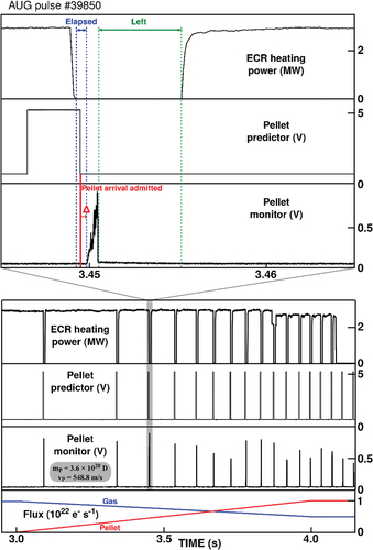
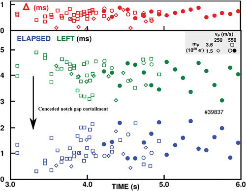
Fig. 2. Time spans obtained as indicated in for duration “Δ” between pellet arrival admitted and the real onset of pellet ablation (upper box), “Elapsed” between heating power off and ablation onset, and “Left” between ablation finished (lower box). Data shown were obtained from six plasma discharges dedicated during the AUG restart phase for PLS commissioning. Pellet injection was tested employing two different sizes and two different velocities, assignment of the according symbols as shown by the inset. “Δ” refers to the predictor precision showing that all pellets are kept safely within the admitted region but at less than 1-ms delay. The larger scatter observed for “Elapsed” and “Left” refers to the DCS cycle time and can be attributed to the pellet launch initiated uncorrelated to the DCS cycle. As requested, all “Elapsed” values stay positive but with no further headroom left. As intended, from the “Left” values, it proves there is headroom for notch curtailment. With three DCS cycles demonstrated not to be needed anymore for safe operation, a reduction to two DCS cycles for the notching tool was approved.
The optimized predictor settings have proven favorable during PLS restart commissioning; a pellet arrival predictor is now at hand at a precision that ensures that the entire pellet ablation process takes place within a 2-ms interval. Hence, for the detection of an expected pellet arrival, analysis can be restricted in this narrow time span. For validation of pellet arrival, considerations can be limited/focused on this narrow time slice.
It is self-evident that this utility was employed for notching improvements as well. However, here, it has to be taken into account that pellet launching times are not correlated to the DCS cycles. Thus, it can take up an entire DCS cycle until the gyrotron off command is communicated. With gyrotron switching faster than 1 ms and less than 2 ms covered by pellet actuation, the notching gap was shortened to two DCS cycles, which is the possible minimum sequence anyway.
III. REAL-TIME MONITORING OF PELLET DELIVERY
In order to provide the information of a missed-out pellet in real time, a new diagnostics has been developed. It relies on the already existing pellet monitor, recording the intense radiation emitted during pellet ablation inside the hot plasma with a microsecond temporal resolution. Though this monitoring approach is likely not the most suited one relevant in EU-DEMO (CitationRef. 8), it was chosen for its simplicity and reliability at AUG and to allow for a straightforward proof-of-principle demonstration. In principle, any suitable pellet monitor signal or even several confirmation techniques can be applied following the same ansatz.
In a first step, a confirmation monitor signal was generated. For cases showing up in the pellet monitor with sufficient radiation level intensity and duration (the latter to eliminate electronic noise spikes), a DCS compatible square pulse “confirmed” is released. In the second step, a dedicated unit in the PLS local control unit compares the pellet predictor and the confirmation signals. In cases where the confirmation signal does not arrive within the predicted time slot, the requested pellet is regarded as missed out, and the according signal pulse is generated. While already generated in real time and communicated to the DCS, the incorporation of this signal into the control algorithm is still pending.
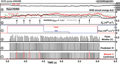
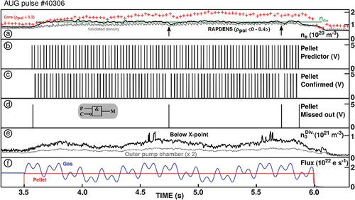
The first successful demonstration of the novel unit is shown in . The discharge displayed was run with plasma current IP = 1.0 MA, toroidal magnetic field Bt = −2.5 T, and edge safety factor q95 = 4.4; H-mode conditions were established and maintained by steady auxiliary heating applying 7.3 MW neutral beam and 2.3 MW ion cyclotron resonance heating. The aim of this experiment was to identify the correlation of the plasma stored energy (box a) and the gas puff rate in the high-density regime accessed by a steady high pellet flux. To do so, the gas flux was reduced in steps to zero (box c). Simultaneously, a strong steady pellet flux was applied (box c) consisting of pellets, each containing 3.6 × 10²⁰ deuterium (D) atoms and injected at a speed of 550 m/s. To deliver the requested flux, the recently installed pellet flux controllerCitation4 toggled between 35 and 47 Hz injection frequency. Trying to consume the entire pellet reservoir, 91 launch attempts took place, each with its accordingly predicted pellet arrival (box e). As indicated by the monitor signal (box d), 85 pellets arrived in the plasma and were correctly confirmed (box f). While processing predictor and confirmation signals, five out of six missed-out pellets were recognized. Six pellets were missed-out during the high flux fueling phase. The effect of such failed pellet delivery can be often traced in the evolution of the plasma density (box b). Displayed are the line-averaged density as obtained by real-time calibrated measurement of the bremsstrahlung (gray, “Validated density” line averaged), a local core measurement by the Thomson scattering diagnostics (red crosses), and the density calculated for the plasma core region by RAPDENS (black). Although available in real time, the latter was not applied for control purposes in this discharge. Because of the significant flux, core densities in the vicinity of the Greenwald density (green) were established and maintained during the pellet phase.
Fig. 3. Demonstration of detecting most missed-out pellets in real time during a performance investigation experiment. The stored energy is investigated at different gas flux levels in the presence of strong pellet fueling ramping up the core density to reactor grade. For every launch attempt, the pellet is announced by the predictor prior to its expected arrival at the plasma edge. Analyzing the ablation monitor signal in real time, either successful pellet delivery is monitored as “Confirmed” or identified as “Missed.” Unwanted drop in density can be correlated to failed pellet delivery (arrows in box b).
IV. ALTERNATIVE PELLET MONITORING TECHNIQUES
Providing an adequate monitor is considered challenging within a reactor environment. In our first proof-of-principle demonstration at AUG shown previously, pellet arrival or loss is detected in real time by the ablation radiation. Once this information is integrated in the control algorithm, losses can be compensated by either fast instant substitutions or adaptation of the pellet flux requested by the control system. Yet, the currently used method requires observation of a considerable fraction of the designated ablation region. However, analysis showedCitation8 that a sufficiently large field of view cannot be covered with reasonable effort in EU-DEMO under current assumptions (pellet flight path, penetration depth, and diagnostic lifetime) and is thus anticipated as being unsuitable. Consequently, alternative methods need to be investigated in parallel. As one option, magnetic pickup coils mounted in a DEMO-like configuration at the vessel exterior of AUG were successfully tested. Despite their moderate sensitivity and temporal resolution, missed-out pellets were well identified, even in plasmas with strong edge localized mode (ELM) activity.
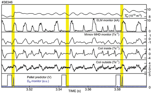
An example is given in . There, a sequence of three pellet launch attempts into an ELMing H-mode is shown. The two arriving pellets show a clear impact on density, ELM monitor, and different magnetic coil monitor signals including one installed in a reactor-relevant configuration outside the vacuum vessel. The missed-out pellet can be recognized from the absence of an according impact within the expected time window.
Fig. 4. Alternative approach for missed-out pellet detection. Even under H-mode with strong ELM activity, with some likelihood such events can be recognized. Relying on pellet arrival is expected only within a short phase, which is visualized by the yellow bars; absence of typical pellet-related impact indicates a missed-out event.
V. REAL-TIME DENSITY MONITORING AND CONTROL WITH PELLET FUELING: FURTHER DEVELOPMENT
The entire approach of pellet core density control relies on three capabilities. The first capability is to reliably monitor the plasma density while pellet injection is ongoing. The second capability is to derive the pellet flux request needed to establish the target density. And, finally, the third capability is to cover the required pellet fueling flux with sufficient preciseness by discrete pellet injection. These basic techniques have already been developed as described elsewhere; hence, just a brief overview is provided here.
The first capability is provided by the state observer RAPDENS (CitationRef. 3), which reconstructs in real time the one-dimensional radial density profile inside the last closed flux surface (separatrix). Optionally, different characteristic density parameters can be derived as, e.g., local densities for any position inside the plasma column or line-averaged or volume-averaged densities for predefined radial regions. For example, in the discharge shown at , the volume-averaged density within the core region containing 40% of the poloidal magnetic flux inside the separatrix (ρpol. 0.0 to 0.4) had been chosen as a control parameter.
Fig. 5. Gas flux modulation in a dedicated system identification experiment. In the presence of strong pellet fueling ramping up the core density to a reactor-grade level, the gas flux is modulated to determine the response of the neutral density in the divertor region. Missed-out pellets are recognized as “Predictor AND NOT Confirmed” (see inset in box d).
To establish or keep a designated target density, the required pellet flux is computed by a proportional-integral controller tuned on the model for the pellet fueling included in RAPDENS (CitationRef. 4). The pellet flux request is calculated for every time step, for adaptation reasons synchronized with the DCS cycle, and, hence, appears as a quasi-continuously evolving trajectory.
Finally, the third capability is provided by a dedicated newly implemented algorithm that calculates the pellet sequence required to match the quasi-continuous flux request. Unlike for gas puff fueling, where such a request can be met by a gradual change of the gas valve dosing rate, pellet fueling takes place as a sequence of discrete injection events, each delivering a quasi-instantaneous amount of fuel predetermined by the pellet particle content. In the case of our centrifuge launcher, these injection events can take place only on a discrete time grid determined by the centrifuge revolution time and the maximum delivery rate of the pellet source. Any of these possible launching slots can be potentially occupied by a single pellet on request.Citation9 Hence, the dedicated algorithm derives the most-suited pattern for the population of the launching slots in order to match the quasi-continuous flux request. Already, during campaign 2021, this solution was applied for several occasions after demonstrating its full viability.Citation4
However, while gaining operational experience and obtained feedback, it became obvious that there is still headroom for further performance enhancement by improvement of the model settings and by embedding this dedicated control feature into the versatile actuator toolbox of AUG. For the complexity of this task and steadily changing requests and boundary conditions, it is understood that this is an ongoing iterative approach to still be continued. Further developments have been envisaged in parallel, as, e.g., the improved precision of pellet prediction and real-time detection of pellet delivery status as discussed before. As well, pellet fueling as the powerful actuator enabling operation at reactor-relevant high core densities has to be integrated into the actuator sharing concept for multiple control tasks. With its special features, it has, e.g., to rely on pellet-resilient diagnostics. And, because it mainly applied to gain access into operational conditions not widely used, it enforces extra effort to sound out the relevant control transfer functions in this regime.
Since here, density profile control is usually aspired by combining pellet and gas fueling, the initial step taken and described in the following was to characterize the response of the gas actuator combined with strong pellet fueling. Basically, this approach aims in the pellets acting on the core density while the edge density is adjusted via gas puff actuation. It turned out to be suitable in experiments demonstrating sustainable and reversible high core density operation while avoiding edge-induced energy confinement degradation by containing the edge density below a critical value.Citation10 However, rigorously taken, both pellets and gas act on the entire density profile. This coupling is neglected to simplify the approach. To better understand the dynamics, characterize the coupling, and develop advanced controllers, perturbative dynamic experiments were performed within the high core density operational range.
An example of such an experiment is shown in . The discharge was run essentially in the same configuration and the same parameter as the discharge shown in . To establish a high core density (box a, the same density signals as shown in ) and grant access to the desired operational regime, again, a strong steady pellet flux (box f) was applied—again, pellets each 3.6 × 10²⁰ D atoms, speed of 550 m/s, and pellet repetition rate toggling between 35 and 47 Hz.
The initial aim of the experiment is to characterize the dynamic response of the edge density with respect to the gas puff. However, because of pellet-induced perturbations, no direct reliable real-time direct measurement of the edge density is available. Therefore, the real-time and pellet resilient neutral gas pressure in the divertor is taken as substitute output. It has been shown in CitationRef. 10 that there is a good correlation under such operational conditions between the relevant edge density inside the separatrix and the neutral gas density in the divertor. To identify the dynamic response of this pressure in different locations (two examples are displayed in box e), the gas flux (box f) was modulated using a multisine perturbation signal with fundamental frequency Hz and harmonics (integer multiples) 5 and 11 Hz.
Again, by processing predictor (box b) and confirmation (box c) signals, all missed-out pellets (box d) are recognized as “Predicted AND NOT Confirmed” (see inset in box d). Two of them originate from the ice rod end tips, and their losses were likely caused by the waiting time for the discharge run after ice rod formation. Two pellets were missed-out during the high flux fueling phase, again causing a local dip in the density evolution (arrows in box a).
The input (deuterium gas puff rate) and output (measured divertor pressure) are superposed in . While a clear relation can be seen, this becomes clearer when the signals are converted to the frequency domain; see . By looking at the relative amplitude and phase of the output signal with respect to the input, the frequency response function (FRF) of the system can be computed.Citation11 This FRF can be depicted in a bode diagram as shown in .
Fig. 6. (Top) Superposed time traces of the deuterium fueling rate (black) and divertor pressure (red) of the dedicated system identification experiments shown in . (Bottom) Amplitude of the discrete Fourier transform of the deuterium fueling rate (black) and divertor pressure (red).
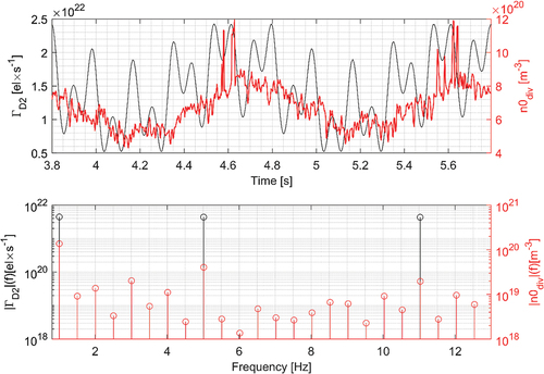
Fig. 7. Magnitude (top) and phase (bottom) of the FRF (blue) obtained using the Local-Polynomial methodCitation17 (LPM) and the bode plot of a first order with delay transfer function (orange). Note that the first-order transfer function was derived based on several system identification discharges. For the discharge shown, only two periods of the excitation signal were used to go this low in frequency. This limits the reliability of the error bars calculated by the LPM. Further analysis is required to understand the behavior of the system in the low-frequency range as it differs from the trend seen in the other system identification discharges and will be reported on in a future dedicated publication.Citation16
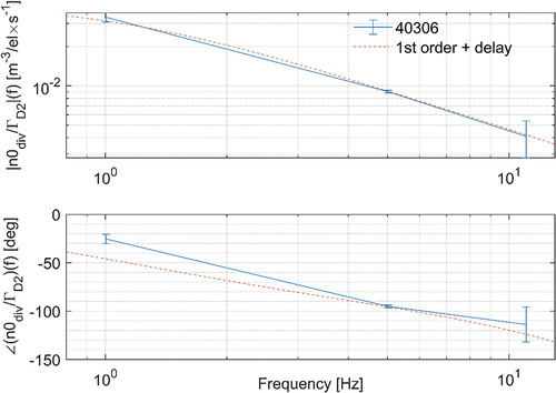
This frequency domain analysis can be used to detect nonlinearities, derive local linear models for the system, perform cross machine comparison, validate first-order models, and aid with the design of controllers (see, e.g., CitationRefs. 12 through 15). For example, the FRFs of the system identification discharges were used to fit a first-order transfer function with a delay term with constant parameters ,
, and
, of the form
where is a complex number frequency parameter called the Laplace variable, with real numbers
and
. The frequency response of
with parameters
,
, and
is shown as the dotted line in . It can be seen that it matches the FTF of the experiment except for the phase at the lowest frequency. Further detailed analysis of these experiments is ongoing and will be reported on in a future publication.Citation16
VI. PROJECTED NEXT STEPS
Taking benefit of the achievements from the 2022 campaign and in preparation for the next campaign, several next steps are envisaged. First, the performed system identification experiments will be used to infer the dynamic response of the plasma to pellet injection and to complete the multiple input multiple output (MIMO) transfer matrix from the inputs gas injection and pellet injection to the outputs core density and edge density. This transfer matrix is envisaged to be used to design MIMO controllers that control the core and edge density using both gas and pellet injection and account for the coupling. Furthermore, missed-out pellet information will be included in the RAPDENS observer, and knowledge of the system dynamics will be used to update the models used in RAPDENS to improve density reconstruction.
In preparation for further refinement, work is in progress on a tool to analyze ablation radiation in real time. Targeting not just to derive information if a pellet is delivered successfully or missed out but also to estimate the arriving pellet mass via the magnitude of the recorded ablation radiation. Variations of the pellet mass could be included in RAPDENS and allow for even better prediction of the expected density evolution.
Lessons learned in this study will also be incorporated in the planning for the EU-DEMO project. Obviously, it is necessary to develop a strategy for missed-out pellet handling. The strategy proposed is based on our recent findings taking into account the current design of the EU-DEMO pellet system layout. This design is displayed in , which is a conceptual drawing that shows an exploratory solution being investigated by the EUROfusion Fusion Technology DepartmentCitation18 and already taken into account for the preconceptual design of the EU-DEMO matter injection system.Citation19 Up to nine pellet casks can be placed above the torus vessel; according space reservations are already in place. As required for efficient particle fueling,Citation20 pellets will be transferred to the torus inboard side via a 25-m-long guiding tube and will finally enter the plasma in free flight.
Fig. 8. Current design model of EU-DEMO with space reserved for up to nine pellet casks and the related pellet guiding tube. Although the detailed design is likely to change, the basic structure, i.e., separated pellet cask and guiding tube of about 25-m length, is not.
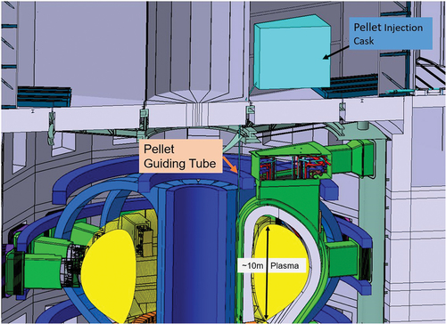
Diagnosing the successful production and launching of a pellet is thus possible by installing a proper diagnostics protected in the cask at the launcher exit. Reliable methods for analyzing the integrity via volume measurements of pellets in flight via shadowgraphy images are available.Citation21 During the transfer via the guiding tube, further diagnosing does not seem adequate: Installing equipment there would be difficult for space restrictions in a harsh environment and would cause the risk of unnecessary pellet losses. Finally, the ultimate check of pellet arrival takes place via detection of arrival in the plasma. Hence, there are mainly two stages of response. A missed-out launch due to failed pellet production or acceleration can already be detected a few milliseconds after the according request. Then, an immediate replacement with the predictor signal adjusted in time is possible due to this delay is much shorter than characteristic response times for burn control. Pellets lost during the transfer or pellets arriving not in proper shape inside the plasma can be recognized in as few as 10 ms after their requested pellet delivery due to the time of flight. In this case, it is likely the controller has to make an according adjustment of the entire flux request.
All the activities described so far aim to enhance the pellet actuator and embed it into the environment of a multiactuator control framework. It should be noted, however, that the pellet injector itself has the potential to act as a multiactuator.Citation4 For example, pellets have proven capable of controlling the frequency of ELMs causing periodic plasma lossesCitation22,Citation23 and mitigating their impact on the wall components exposed.Citation24 Yet, recently revalued, this potential has become less reactor relevant; it showed the capability of pellet actuation beyond sole fueling. On the other hand, the technique of plasma seeding by gases needed for either performance enhancementCitation25 and/or radiative power exhaustCitation26 has been found to work better with pellet doping than with pure gas puffing.Citation27 On that account, pellets can turn out to be beneficial for yet unknown applications in the future. Hence, the broader approach for a reactor-grade pellet system is to develop a multiactuating tool capable of serving a couple of different tasks simultaneously. As a potential prototype system of this kind, the pellet system for the new superconducting large tokamak JT-60SA is currently under manufacturing. In its initial start-up configuration, it is envisaged to allow in-parallel fueling and ELM pacing, its design allowing extension for a third possible option.Citation28
VII. SUMMARY
The development of a suitable control tool for the pellet actuator is recognized as an important task for EU-DEMO. In order to grant access to the desired high core density regime needed to harvest sufficient fusion power, pellet injection from the torus vessel inboard side is concluded a sine qua non. However, recent modeling efforts unveiled requested, but missed-out pellets do potentially form a severe problem for burn power control. Consequently, an approach is required allowing fast recognition of such events and a suitable strategy for a timely and sound response. At AUG, an algorithm was developed and successfully tested during plasma operation that was able to detect missed-out pellets in real time. This current approach relies on pellet ablation radiation.
Since it might cause too much effort in EU-DEMO to install ablation radiation diagnostics,Citation8 an alternating approach relying on magnetic pickup coils was tested as well. For the recognition of pellet arrival in the plasma via its impact on properly diagnosed parameters, it is considered advantageous to precisely predict the pellet arrival time. Centrifuge acceleration systems are most suited to achieve this.Citation29
Making use of optimized predictor algorithms, the performance of the AUG pellet launcher with respect to this precision was improved further. Beyond its application in missed-out pellet detection, this turned out to be beneficial for other applications as well as for minimized notching.
To make the best use of the pellet actuator, it has to be properly embedded into the full actuator tool box. The initial approach at AUG combined pellets and gas to control the density profile. Employing pellet resilient control parameters for core and edge density, this already worked well by attributing the pellet actuator to core and gas puffing to edge control. However, further refinement needs to take into account the full impact of both actuators on the entire density profile. Therefore, system identification experiments have been performed sounding out the dynamics of the gas actuator in the relevant high-density regime. Sought-after data have been achieved, and detailed analysis is still ongoing aiming for an updated model in RAPDENS. It is understood that controller improvement will be an iterative process, further gradually enhancing the entire control system step-by-step.
With pellets proven to be a powerful actuator even beyond the pure fueling task, this enhancement finally aims at a pellet tool capable of covering several assignments in parallel. Currently, such a system is under development for JT-60SA, fostering further development of reactor-relevant pellet technology.
Acknowledgements
This work has been carried out within the framework of the EUROfusion Consortium, funded by the European Union via the Euratom Research and Training Programme [grant agreement number 101052200—EUROfusion]. Views and opinions expressed are however those of the author(s) only and do not necessarily reflect those of the European Union or the European Commission. Neither the European Union nor the European Commission can be held responsible for them.
Disclosure Statement
No potential conflict of interest was reported by the author(s).
References
- F. JANKY et al., “Kinetic Control,” Proc. 5th IAEA DEMO Programme Workshop, Daejeon, Korea, May 2018, International Atomic Energy Agency (2018).
- P. T. LANG et al., “Optimizing the EU-DEMO Pellet Fuelling Scheme,” Fusion Eng. Des., 156, 111591 (2020); https://doi.org/10.1016/j.fusengdes.2020.111591.
- T. BLANKEN et al., “Model-Based Real-Time Plasma Electron Density Profile Estimation and Control on ASDEX Upgrade and TCV,” Fusion Eng. Des., 147, 111211 (2019); https://doi.org/10.1016/j.fusengdes.2019.05.030.
- P. T. LANG et al., “Actuator Development Step by Step: Pellet Particle Flux Control for Single- and Multiple-Source Systems,” Fusion Sci. Technol., 78, 1 (2022); https://doi.org/10.1080/15361055.2021.1940034.
- C. ANDELFINGER et al., “A New Centrifuge Pellet Injector for Fusion Experiments,” Rev. Sci. Instrum., 64, 4, 983 (1993); https://doi.org/10.1063/1.1144101.
- M. MARASCHEK et al., “Path-Oriented Early Reaction to Approaching Disruptions in ASDEX Upgrade and TCV in View of the Future Needs for ITER and DEMO,” Plasma Phys. Control. Fusion, 60, 01447 (2018); https://doi.org/10.1088/1361-6587/aa8d05.
- B. PLOECKL et al., “The Enhanced High Speed Inboard Pellet Fuelling System at ASDEX Upgrade,” Fusion Eng. Des., 88, 1059 (2013); https://doi.org/10.1016/j.fusengdes.2012.12.025.
- A. KRIMMER et al., “Pellet Monitoring Diagnostic System,” EFDA_D_2PJA3U, EUROfusion.
- B. PLOECKL et al., “Targeting a Versatile Actuator for EU-DEMO: Novel Control Scheme for Multisource Pellet Injector,” Fusion Sci. Technol., 77, 199 (2021); https://doi.org/10.1080/15361055.2020.1864172.
- P. T. LANG et al., “H-Mode Confinement in the Pellet-Enforced High-Density Regime of the All-Metal-Wall Tokamak ASDEX Upgrade,” Nucl. Fusion, 60, 092003 (2020); https://doi.org/10.1088/1741-4326/ab6ea9.
- R. PINTELON and J. SCHOUKENS, System Identification: A Frequency Domain Approach, 2nd ed., Wiley, New York (2012).
- J. T. W. KOENDERS et al., “Systematic Extraction of a Control-Oriented Model from Perturbative Experiments and SOLPS-ITER for Emission Front Control in TCV,” Nucl. Fusion, 62, 066025 (2022); https://doi.org/10.1088/1741-4326/ac5b8c.
- T. RAVENSBERGEN et al., “Real-Time Feedback Control of the Impurity Emission Front in Tokamak Divertor Plasmas,” Nat. Commun., 12, 1105 (2021); https://doi.org/10.1038/s41467-021-21268-3.
- T. O. S. J. BOSMAN et al., “Model-Based Electron Density Profile Estimation and Control, Applied to ITER,” J. Phys. Commun., 5, 115015 (2021); https://iopscience.iop.org/article/10.1088/2399-6528/ac3547.
- G. DERKS et al., Plasma Phys. Control. Fusion, 64, 125013 (2022); https://iopscience.iop.org/article/10.1088/1361-6587/ac9dbd.
- T. O. S. J. BOSMAN et al. “Overview and results of the system identification experiments for detachment and MIMO density control at ASDEX Upgrade,” (2023), in preparation.
- M. VAN BERKEL et al., “Correcting for Non-Periodic Behaviour in Perturbative Experiments: Application to Heat Pulse Propagation and Modulated Gas-Puff Experiments,” Plasma Phys. Control. Fusion, 62, 094001 (2020); https://doi.org/10.1088/1361-6587/ab9eaa.
- C. GLISS, EUROfusion Fusion Technology Department, Personal Communication (Apr. 25, 2022).
- B. PLOECKL et al., “Matter Injection in EU-DEMO: The Preconceptual Design,” Fusion Sci. Technol., 77, 266 (2021); https://doi.org/10.1080/15361055.2021.1903784.
- P. T. LANG et al., “Considerations on the DEMO Pellet Fuelling System,” Fusion Eng. Des., 96–97, 123 (2015); https://doi.org/10.1016/j.fusengdes.2015.04.014.
- T. SZEPESI et al., “Volume Measurement of Cryogenic Deuterium Pellets by Bayesian Analysis of Single Shadowgraphy Images,” Rev. Sci. Instrum., 79, 3, 033501 (2008); https://doi.org/10.1063/1.2870089.
- P. T. LANG et al., “ELM Pace Making and Mitigation by Pellet Injection in ASDEX Upgrade,” Nucl. Fusion, 44, 665 (2004); https://doi.org/10.1088/0029-5515/44/5/010.
- M. LENNHOLM et al., “Statistical Assessment of ELM Triggering by Pellets on JET,” Nucl. Fusion, 61, 36035 (2021); https://doi.org/10.1088/1741-4326/abd861.
- L. R. BAYLOR et al., “Reduction of Edge-Localized Mode Intensity Using High-Repetition-Rate Pellet Injection in Tokamak H-Mode Plasmas,” Phys. Rev. Lett., 110, 24, 245001 (2013); https://doi.org/10.1103/PhysRevLett.110.245001.
- M. G. DUNNE et al., “The Role of the Density Profile in the ASDEX-Upgrade Pedestal Structure,” Plasma Phys. Control. Fusion, 59, 014017 (2017); https://doi.org/10.1088/0741-3335/59/1/014017.
- A. KALLENBACH et al., “Developments Towards an ELM-Free Pedestal Radiative Cooling Scenario Using Noble Gas Seeding in ASDEX Upgrade,” Nucl. Fusion, 61, 016002 (2021); https://doi.org/10.1088/1741-4326/abbba0.
- A. KALLENBACH et al., “Argon Doped Pellets for Fast and Efficient Radiative Power Removal in ASDEX Upgrade,” Nucl. Fusion, 62, 106013 (2022); https://doi.org/10.1088/1741-4326/ac888a.
- P. T. LANG et al., “A Flexible Pellet Injection System for the Tokamak JT-60SA: The Final Conceptual Design,” Fusion Sci. Technol., 75, 178 (2019); https://doi.org/10.1080/15361055.2018.1471960.
- B. PLOECKL et al., “Comparison of Different Pellet Injection Systems for ELM Pacing,” Fusion Eng. Des., 86, 1022 (2011); https://doi.org/10.1016/j.fusengdes.2011.02.007.