
 ?Mathematical formulae have been encoded as MathML and are displayed in this HTML version using MathJax in order to improve their display. Uncheck the box to turn MathJax off. This feature requires Javascript. Click on a formula to zoom.
Abstract
Robot-assisted rehabilitation is a rapidly advancing field whereby robotic devices are used for the treatment of disabilities. Mechanism design and actuation of these devices play important roles in the treatment and the non-ergonomic designs may even increase the cardiorespiratory load and cause discomfort leading to further gait disorders. This article identifies crucial design and actuation aspects of gait rehabilitation robots and presents the first intrinsically compliant gait robot design with three actuated and five passive degrees of freedom, alleviating the prevalent issues. The gait robot joints remain aligned with the human anatomical joints during the swing and the stance phases due to the use of special bushes and dampers. The intrinsically compliant actuators on the new gait robot make it safe to work with human subjects. Increased degrees of freedom allow for natural walking dynamics instead of canceling or constraining them. The robot firmware, including the kinematic modeling, is designed using multiple adaptive neuro-fuzzy inference system to save on the computational time of the robot controller. The new robot design is finally validated for its intended use in gait rehabilitation, by employing a fuzzy logic controller and evaluating the position, velocity, and acceleration profiles of its joints.
1. Introduction
Neurological disorders and injuries may result in gait disorders or disabilities, which may be corrected or reinstated with physical therapy. The aging world’s population and the present demographic and health shifts are causing a precipitous increase in the number of people with disabilities or waning functions. This trend calls for prioritizing rehabilitation services for valid reasons. In general, rehabilitation is intended to help anyone having difficulties in mobility, cognition, or vision and, therefore, has a very wide scope (Cieza et al. Citation2020). Post-stroke disability treatments usually require physical rehabilitation, which is carried out by trained therapists with passive devices (Kim, Lee, and Lee Citation2021). To support these therapists in treating their patients effectively and efficiently, robotic solutions have been devised (Kapsalyamov et al. Citation2019; Kapsalyamov, Hussain, et al. Citation2020). While some of these robotic devices are used in clinical settings, there is a large number of such devices, which are investigated in research laboratories. The devices being used in the clinics normally are simple solutions consisting of basic feasible designs operated by conventional controllers, which are derived from industrial robots. The commercially available rehabilitation equipment required to reinstate lower limb post-stroke disabilities is usually very expensive (Cieza et al. Citation2020).
The conventional approach for rehabilitation needs much more effort from therapists and a long time to treat disabilities. Therefore, designing and developing robotic orthoses for intensive, customized, and low-cost physical therapy for stroke survivors’ rehabilitation is important and meaningful to ensure those patients could engage in social activities without help (Carlo Citation2009). Rehabilitation robots are generally programmable and integrated with a variety of sensors, which can provide accurate information for therapists to provide personalized training of different intensities and modes according to the varied classes and severities of disabilities (Marchal-Crespo Citation2007; Ramirez-Bautista et al. Citation2017; Young and Ferris Citation2017; Ramirez-Bautista et al. Citation2018). These rehabilitation robots are normally of two types, one which mimics the therapist is called an end-effector robot, and the other class of robots is called exoskeletons, which will emulate the human limbs closely (Jamwal et al. Citation2018; Hussain et al. Citation2020). These exoskeleton-type robots are attached to the human limbs using braces and are expected to move human limbs, maintaining close alignment between exoskeleton joints and human joints.
It has been established that for effective treatment, subjects should participate actively and consciously while using these exoskeleton-type robots during their rehabilitation process (Hussain et al. Citation2017; Young and Ferris Citation2017). To enhance patients’ participation, the robots should be ergonomically designed, in other words, the robots should have sufficient degrees of freedom () to provide users a natural walking experience (Reinkensmeyer, Emken, and Cramer Citation2004; Hogan et al. Citation2006; Hussain Citation2014; Huang, Tu, et al. Citation2016; Jamwal and Hussain Citation2016; Jamwal et al. Citation2016; Chaparro-Cárdenas et al. Citation2018). There are challenges in meeting the flexibility requirement in robot designs owing to various reasons, such as, (
) the complex kinematics of human joints cannot be modeled in terms of the sequence of simple kinematic pairs,
the dimensional details of the anatomical joints cannot be obtained from in-vitro measurements, and
the wide variability in terms of anthropometric measurements of subjects (Schiele and Van Der Helm Citation2006). Apart from the inconvenience, the compromised flexibility in robot designs may cause residual forces on the subjects at the points of interfaces, resulting in pain or further disorders with long-term uses.
There are two ways to increase degrees of freedom in robot designs and make them more flexible. Firstly, by providing multiple at every anatomical joint to allow rotational motions in all three planes (sagittal, frontal, and transverse). Secondly, the robot design can be made more flexible by allowing some displacements together with the required rotational motion at each of the joints (Reinkensmeyer, Emken, and Cramer Citation2004; Hogan et al. Citation2006; Hussain Citation2014; Huang, Tu, et al. Citation2016; Jamwal and Hussain Citation2016; Jamwal et al. Citation2016; Chaparro-Cárdenas et al. Citation2018). Increasing the design flexibility will exponentially increase the complexity of the kinematic analysis and the controller design. This further explains why the commercially available robots adopt a simpler design and, hence, simpler control approaches (Weber and Stein Citation2018).
A multi-DOF compliant gait rehabilitation robot offers more flexibility in motion kinematics which further means less constrained motion. Such design shall help in providing natural motions instead of canceling or restraining some of the DOFs. A multi-DOF robot provides one-to-one mapping or correspondence between robot joints and human anatomical joints. Such configuration of a robot can be utilized to work with joint differently and in isolation. For instance, while working with a subject whose knee joint is stiff whereas hip and the ankle joints have full ranges of motions, it is possible to actuate only knee joint of the robot while the hip and ankle motions are achieved by the subject themselves.
A major practical challenge to the comfort and usability of robots is the need to avoid misalignment of the exoskeletal joint with the aligning human joint. Robotic exoskeletons normally have simple revolute joints, while human joints have translating axes of rotation. As such the two, robot and human joints, cannot remain aligned during motions. Consequently, this axis misalignment induces compensatory movements that will not only impede recovery but will also cause discomfort to the subjects due to undesired residual forces. Such misalignment may also be caused by the compression of soft tissues interacting physically with the robot or due to the use of flexible braces while fixing robots on the subjects’ limbs.
Subsequently, researchers have proposed novel self-aligning mechanisms that can be used in robots. Analytically, it has been shown that the use of a self-aligning or allying mechanism may reduce the residual forces and torques substantially (Schiele and Van Der Helm Citation2006; Cempini et al. Citation2013; Wang et al. Citation2014). Lately, robots employing a self-aligning mechanism have been designed and proposed for lower limb rehabilitation (Giovacchini et al. Citation2015; Saccares, Sarakoglou, and Tsagarakis Citation2016; Hyun et al. Citation2017; Junius et al. Citation2017) as well as for robot-assisted rehabilitation of the human upper limbs (Cempini et al. Citation2013). Nevertheless, most of the self-aligning mechanisms for lower and upper limb robots are either too complex to be practically used or they still produce residual or uncompensated forces/torques.
Assumptions that these allying mechanisms are massless, frictionless, and infinitely stiff do not practically hold during implementations. The finite mass of these allying mechanisms induces unpredictable forces and torques, which adversely affect their intended objective. The presence of friction in the mechanism may prevent the mechanism from dynamically aligning in real-time. Compliance in the linkages of the allying mechanisms may also induce passive movements that may give rise to uncertain kinematic behavior. Therefore, it is challenging to design and develop an allying mechanism that has low mass and frictions and is sufficiently robust to transfer motions without altering them.
Apart from the above attributes, a good allying mechanism will also have a good decoupling approach, which allows large residual forces to be transferred to the exoskeletal system (Stienen et al. Citation2009; Cempini et al. Citation2013; Otten et al. Citation2015; Zanotto et al. Citation2015). Decoupling of joint rotations and translations also plays an important role in achieving the self-alignment of robotic exoskeletons. An allying mechanism with a provision for decoupling can reduce the interaction stiffness between the robot and the human lower limbs.
Actuation in rehabilitation robots plays an important role and compliant actuators such as pneumatic muscles are preferred over stiff electromagnetic actuators owing to their lightweight, compliant motions, and skeletal muscles-like behavior.
Compliant actuation is important for rehabilitation robots that work in close proximity of human users. First and the foremost benefits is the safety and comfort for the subjects. During the initial stage of rehabilitation, usually subjects’ ranges of joint motions are limited, and a robot actuated by stiff electric motors might move subjects’ limbs beyond this limit causing pain and discomfort. Compliant actuators are also backdrivable and can easily be retracted in such case whereas the electric motors cannot be retracted easily. Electric motors (weighs close to 1.5–2 kg) are normally 20 times heavier than the compliant actuators (weighs only 80 g each) and therefore the compliant actuators have high power to weight ratio compared to the electric motors. Light weight of compliant actuators also helps in avoiding any slippage between robot and human joints thus facilitating appropriate alignment between them.
A few designs of gait robots actuated by pneumatic muscles have been proposed in the literature, however, only two dof have been implemented in these designs due to design complexities that arise from the use of the pneumatic muscles. Moreover, most of them do not have a telescopic feature and rather have fixed link lengths, which prevents their use for a wide subject population that will require length adjustments. One example is (Cao, Xie, and Das Citation2018) where only one leg of the 2-dof robot is presented and the design is not adaptable to different user sizes. Further, it is known that an average torque of 60 Nm is needed to move the hip joint and 15 to 20 Nm torque is sufficient for the knee joint motions during the human gait (Winter Citation2009). Therefore, for the hip motions, two antagonistically actuated pneumatic muscle actuators (PMA), (inflated with pressure and separated by 6 cm) must individually produce
force. In Cao, Xie, and Das (Citation2018), such torque is claimed to have been achieved with
pressure, which appears to be unrealistic. In (Chang Citation2010), the authors have presented a 2-dof gait robot that is claimed to be providing the required hip and knee torques with 20 mm and 10 mm diameter pneumatic muscle actuators. The data sheet from the FESTO® does not verify this claim (Festo_Corporation Citation2022) and according to this data sheet, the maximum possible force from a 9-meter-long actuator of 20 mm diameter is only
Beyl et al. (Citation2009) presented a single leg of their pneumatic muscle actuated gait robot with just one dof at the knee joint. Huang, Huang, Tu, et al. (Citation2016) proposed a 2-dof robot design and tested its hip joint motions assuming the weight of the human leg as
which is an unrealistic measure.
Three important inferences can be drawn from the above discussion. First and foremost is that there is no 3-dof pneumatic muscle actuated gait robot proposed in the literature so far. Secondly, all of these intrinsically compliant gait robots have fixed link lengths and cannot be adapted to different user sizes. Finally, the above-mentioned gait robots cannot provide the required torques at the hip and the knee joints, which is crucial for an effective rehabilitation treatment.
In an attempt to address the above issues, an intrinsically compliant gait rehabilitation robot with three actuated degrees of freedom is proposed for the first time in this article. The robot design is flexible and can be personalized with the use of telescopic thigh and shank parts. The compliance in the robot system is intrinsic due to the use of Pneumatic Muscle Actuators (PMAs). The PMAs have been carefully selected to provide the required torques at the hip and knee joints during the gait motion. Mechanical amplification of the actuation from the PMAs has been achieved using gears. The knee joint on the robot has been designed to remain aligned with the human knee during the gait cycle. There are passive joints that make the robot design more flexible to provide a natural walking experience to the users. The new robot design, together with its special knee joint, is discussed in detail in the following section. Compliant actuation and its amplification is explained in Sec. 3 and various algorithms that are designed and implemented on the robot system as robot firmware are explained in Sec. 4. An evaluation of the robot design together with other results is provided in Sec. 5 and conclusions from the present work and future directions are discussed in Sec. 6 of the article.
2. New gait robot design
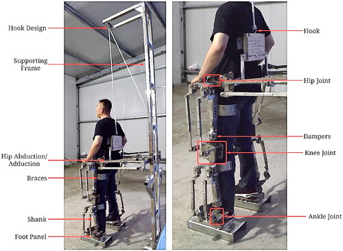
The new gait robot design has hip, knee, and ankle joints that are actuated by pneumatic muscle actuators. The hip joint has actuated flexion/extension motion in the sagittal plane, passive abduction/adduction on the frontal or coronal plane, and passive rotation on the transverse or horizontal plane. The hip joint on the gait robot design, therefore, can provide 3-dof. The robot knee joint can provide actuated flexion/extension in the sagittal plane and small passive rotation on the transverse plane. However, owing to the small transverse rotation available, the knee joint is considered to have a single dof. The robot ankle joint can provide actuated plantarflexion and dorsiflexion in the sagittal plane, passive abduction, and adduction in the frontal plane, and passive inversion and eversion in the transverse plane (Winter Citation2009). The robot system is equipped with a gravity balancing mechanism that keeps the mechanism in equilibrium at various configurations. This further means that the human subject using this robot shall not be subjected to fatigue, which is normally caused by the robot’s weight. The gravity balancing mechanism and the design details of the robot joints are discussed in the following sections.
2.1. Gravity balance mechanism design
The proposed gait robot design needs to be gravity balanced to avoid potential slippage when it is fixed to the users’ limbs. In other words, the actuator forces should not be required at the joints to maintain system equilibrium at various configurations. A gravity balance mechanism can also reduce the forces needed to actuate the robotic exoskeleton during the course of rehabilitation (Agrawal and Fattah Citation2004). Counterweights, springs, and auxiliary parallelograms to determine the center of gravity are known as three commonly used gravity balancing methods (Agrawal and Fattah Citation2004). The theory of using both auxiliary parallelograms and springs is proven to effectively achieve full or partial gravity balancing for human legs within the range of motion (RoM) (Agrawal and Fattah Citation2004; Banala et al. Citation2006). It is also found that flexure springs can achieve gravity balancing by increasing the power/weight ratio and by reducing 81% of spring strength at the same time (Tschiersky et al. Citation2019). So far, these gravity balancing theories have not been applied to improving robotic orthoses (Agrawal and Fattah Citation2004; Banala et al. Citation2006; Tschiersky et al. Citation2019).
In our proposed design, gravity balancing has been applied to the two dof motions, namely flexion, and extension at hip and knee joints of the robot. A hybrid method of gravity balancing has been adapted whereby springs are used and placed appropriately after identifying the center of mass of the robot elements. Partial gravity balancing has been obtained for the robot to offer wide-ranging degree of gravity balancing to the subjects of varying capabilities (Zhou et al. Citation2020).
First, the link dimensions of the robot are used to find trajectory of the center of mass (COM) of its elements in the sagittal plane. Masses of the thigh and shank sections are assumed to be lumped as point masses at their respective COM. Later, the parameters and positions of the springs are selected in such a manner that the total potential energy of the robot system remains constant in various configurations. It should be noted here that the positions of the springs can be changed suiting individual subject’s anthropometric measurements. The potential energy of the robot system can be defined as the sum of potential energies of the springs and the gravitational potential energy as explained below ().
(1)
(1)
Here, and
can be obtained using the cosine law as
Spring stiffnesses
and
are derived from the above relation Equation(1)
(1)
(1) using the condition for static balancing or the condition of minimum potential energy. The spring stiffnesses in terms of the robot mass and its configuration are defined below.
(2)
(2)
(3)
(3)
Figure 1. Implementation of gravity-balancing mechanism applied on the prototype.
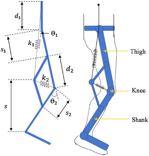
The prototype developed in the University of Canberra lab is not optimized for weight, rather it has been developed to demonstrate the design efficacies and therefore it weighs 110 kg. The weight of the robot thigh segment of one of the legs is 25 kg. The total weight of the shank and foot segments in one of the robot legs is 30 kg. The weight of the human test subject’s thigh segment is found to be 6.4 kg, whereas their shank and foot segments weighed 3.6 kg. Stiffnesses of the springs using these values can be derived in terms of the adjustable distances and
as
and
2.2. Robot hip and pelvis joints
The robot prototype has provisions for the pelvic motions and also allows the requisite trunk motion during the gait motion. The pelvic part of the gait robot is designed to be telescopic to accommodate subjects of the different physiques. The height of the pelvic joints should be more than the height of hip joints with reference to the ground (Sarkisian et al. Citation2020) and, therefore, there are two L-shaped links provided to raise the pelvic joints (). Such design flexibility has no adverse effect on the robot’s gait motion. At the top of the pelvic joints, there is a hook to hold a spring with high elastic coefficient, which is used for the gravity balancing. The telescopic design at the pelvis support helps in adjusting the distance between the robot legs ().
Figure 2. (a) Telescopic Pelvis support on the gait robot. (b) The hip joint linked with the pelvic support on the gait robot. (c) The knee joint with the meshing gears and damper.
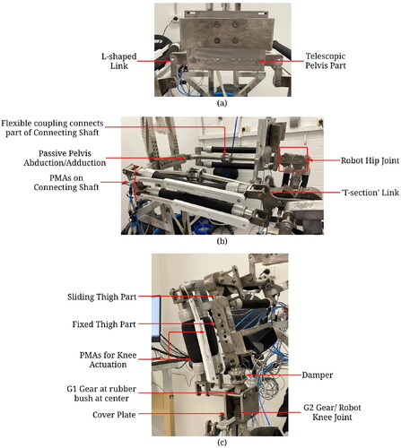
The ends of the pelvis support and the hip joints on the robot () are joined together with the help of a connecting shaft, which is made of two segments connected through a flexible coupling at the center to adapt for any misalignment. The pelvis part is pinned with the connecting shaft to passively allow for the abduction/adduction motion at the pelvis joint. The connecting shaft also has two PMAs mounted on it and their antagonistic actuation moves the robot hip joint in its sagittal plane. The large torque requirement (60 N-m) at the hip joint is achieved by using longer PMAs with large diameters. The longer PMAs can not be accommodated vertically in the robot leg and, therefore, are installed between the robot leg and its supporting frame (). The actuating ends of the two PMAs are connected with a special ‘T-section’ link, which houses a gear at its tail. The antagonistic motion of the PMAs rotates the ‘T-section’ and this in turn rotates the gear attached at the tail of the ‘T-section’ link. This gear in turn is meshed with another gear, which is mounted on the top of the robot’s thigh part and, thereby, the antagonistic actuation of the PMAs moves the robot thigh segment in the sagittal plane. The PMAs have linear encoders attached and can provide information on their individual displacements.
There is another pair of PMAs employed to actuate the robot knee joint and these are mounted on the thigh part of the robot. The thigh and the shank segments are designed in two parts (the upper and the lower parts), which can slide into each other. This feature makes the thigh and shank sections telescopic to accommodate adjustments required when the gait robot is used by different subjects. The telescopic feature on the thigh segment has six holes, which are 20 mm apart, while the shank telescopic feature has five holes spaced at 20 mm. Besides adapting the robot design to different users, the telescopic feature also improves portability and saves storage space since the entire robot structures can be downsized by sliding parts of thigh and shank segments into each other.
Unfortunately, it is not possible to change nominal lengths of the PMAs during such adjustments and, therefore, the PMAs are mounted only on the lower thigh part, which is also the sliding thigh part. This is an important design feature on this robot, which allows telescopic thigh and shank sections without altering lengths of PMAs.
2.3. Robot knee joint
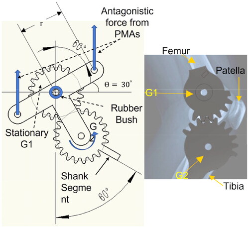
The knee joint is formed with two meshing gears of the same pitch, a nonmoving gear G1 at the top and a movable gear G2, which also acts as the robot knee joint (). The nonmoving gear (G1) is fixed at the end of the thigh segment, whereas the other meshing gear (G2) is connected with the shank of the robot and can rotate. The two actuating ends of the PMAs (which are used to actuate the knee joint) and the axis of G2 are rigidly connected at three points on a cover plate forming another ‘T-section’ such that during the antagonistic actuation of the PMAs, an anticlockwise moment (up to 60 N-m) from the PMAs rotates the gear G2 over G1 anticlockwise from 0 to 60 degrees. The top meshing gear G1 also has a lock that prevents gear G2 to rotate in the clockwise direction and, therefore, the knee joint can only have flexion motion and cannot extend. The PMAs employed cannot contract more than 10% of their nominal lengths and this limits the achievable rotational motions at the robot joints. To achieve the required hip, knee and ankle motions, the actuation from PMAs needs to be amplified. There are two ways to achieve larger actuation from PMAs, either by employing PMAs of longer nominal length or by amplifying the actuating signal by mechanical means. The telescopic feature in the thigh and the shank sections poses a constraint on the PMA lengths to be short. Therefore, in the proposed gait robot design, the actuation is mechanically amplified by using two meshed gears G1 and G2. It is evident from that a 30 degree rotation received from antagonistic actuation of PMAs can be converted to 60 degree rotation of the shank segment. Two cover plates are provided on both sides of the gears G1 and G2 for safety reasons. The cover plates prevent user’s clothes being snagged into the gears.
Figure 3. Amplification of PMA actuation using gears.
2.4. Alignment between robot and human knee joints
The human knee joint complex is formed by the patella bone together with the ends of the femur and tibia bones. It is a complex joint that provides three dof during walking over ground at natural speeds. While flexion-extension is the most pronounced rotation, a small internal-external rotation and abduction-adduction is also observed during the gait cycle (Gray et al. Citation2019).
The proposed new design of a gait robot offers passive internal-external rotation and abduction-adduction motions besides active flexion-extension motion at the knee joint. Gears G1 and G2, that form the robot knee, have rubber bushes at their centers to eventually provide small passive motion in the transverse and the coronal planes. The cushioning effect of rubber bushes also emulates the cartilages in the human knee acting as shock absorbers.
A damper consisting of damper springs is provided on the robot thigh part immediately before gear G1 as shown in . This damper serves two important purposes and the first one is to passively contribute toward the internal-external rotation and abduction-adduction motions of the knee joint. Secondly, the damper also serves as a safety device for the PMAs. In fact, to achieve the antagonistic actuation of two PMAs, one of them is contracted by inflating with high pressure (up to 8 bars). Since the actuating ends of the two PMAs are coupled through a link that forms a moment arm, contraction in one causes extension in another PMA. However, during this process, the link, forming the moment arm, also undergoes a small displacement, which cannot be restrained. The damper serves the important task of providing the necessary small displacement at the moment arm and, thereby, prevents the PMAs from potential bursting from high inflating pressure.
2.5. Robot ankle joint
As discussed in Sec. 2.2, the robot shank part is also telescopic and so has been designed in two parts, which can slide into each other, adjusting its length to accommodate different subjects. The PMAs, which are used to actuate the ankle joint, is mounted on the sliding part of the robot shank and, therefore, their lengths do not require to be altered during such the length adjustments ().
Figure 4. Robot shank and ankle joint.
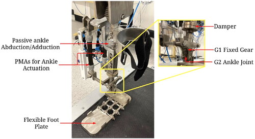
The human ankle joint has three rotational dof, collectively provided by the ankle and the subtalar joints, commonly referred to as the ankle complex. The three degrees of freedom are plantarflexion-dorsiflexion in the sagittal plane, eversion-inversion in the frontal plane, and abduction-adduction in the transverse plane. However, during the gait motion, the ankle predominantly moves in the sagittal plane with small rotations () in the frontal and transverse planes (Brockett and Chapman Citation2016). The ankle joint in the proposed robot design can provide actuated plantarflexion-dorsiflexion motions, while the other two rotations are provided passively. A flexible coupling, provided on the top non-sliding part of the shank, facilitates small passive abduction-adduction, which is required during walking. The damper, provided on the sliding part of the robot shank, allows small eversion-inversion besides serving as a safety device for the PMAs as explained in the previous section. Two meshing gears G1 (fixed) and G2 (movable) are used to provide ankle sagittal plane motion () in the same manner as they were used in the robot knee joint. The flexible foot plate in the gait robot conforms to the sole of users’ shoes and allows passive metatarsal motion during gait.
2.6. Robot workspace analysis
The new gait robot design was evaluated in terms of its capability of providing the required ranges of motions during gait at various joints. Human lower limb motions include a varied range of motions at hip, knee, and ankle joints for different tasks. In the present research, while considering the functional range of motions at these three joints for ambulation (predominantly in the sagittal plane), a study carried out by Yao et al. (Citation2019) has been referred. The results from the RoM experiments are provided in .
Table 1. Ranges of motions at various joints of the new gait robot design.
2.7. Robot safety aspects
Safety is an important consideration while developing rehabilitation robots and while building the proposed gait robot we have considered several safety aspects mentioned below:
Patient safety: While using a gait robot, a protocol is followed with inclusion and exclusion criteria for the subjects as the first point of patient safety. Further, the proposed gait robot legs are design to provide unconstrained motions using dampers and passive degrees of freedoms. For enhanced patient safety, cover plates are provided on both sides of the gears G1 and G2 to prevent user’s clothes being snagged into the gears.
Mechanical safety: The gait robot structure is mechanically rigid and stable to maintain balance during the treadmill-based training. This includes use of high-quality materials for harnesses and the gravity balance systems. The gait robot system also has required safety features, such as emergency stop buttons, to prevent accidents.
Actuation safety: The proposed gait robot is actuated using PMAs which work on compressed air and as such it does not require electrical safety features to prevent electrical shock. Actuation from PMAs is smooth and backdrivable that aids to the safety of actuation. While controlling robot motions, we ensure that pressure in PMAs remain within permissible range (up to 6 bars). The gait robot is recommended to be used under supervision to provide a safe and effective therapy for patients with walking impairments.
3. Actuation design
As discussed in the previous section, pneumatic muscle actuators (PMAs) are used to actuate the proposed gait robot. This actuator is made of a segment of sealed rubber tube wrapped in high-strength fiber. This fiber forms a three-dimensional rhomboid network structure around the rubber tube to allow deformations (Qian et al. Citation2023). The initial force of air muscles is much larger than the traditional pneumatic cylinders with the same diameter. Even in the case of overload, the dynamic characteristics of pneumatic muscles remain stable (Klein et al. Citation2008; Mat Dzahir and Yamamoto Citation2014). PMAs exhibit five times higher power/weight ratio and power/volume ratio in comparison to usual DC motors or hydraulic cylinders (Reynolds et al. Citation2003). When the PMAs are inflated, the diameter of their internal air bladder increases together with the protective outer sheath and the length contracts. This lengthwise contraction and the axial force generated due to inflation is used for the actuation.
These PMAs have properties similar to human skeletal muscles and therefore they have been widely used in robotic manipulators and rehabilitation prototypes (Zhang et al. Citation2019). However, their transient and nonlinear behavior, which mainly comes from the hysteresis effect of the inside latex tube, is difficult to model and there have been many attempts by researchers in past to model the dynamics of PMAs. In one of the earliest works (Chou and Hannaford Citation1994), a linearized model was proposed relating the extension and force at constant pressure. Improvements to this model were later suggested in Tondu and Lopez (Citation1995), Tsagarakis and Caldwell (Citation2000), and Colbrunn, Nelson, and Quinn (Citation2001) that improved the positional accuracy up to 5%. Later, a three-element mechanical model of PMAs was proposed by Reynolds et al. (Citation2003) and is commonly used to describe PMA dynamics.
If the pressure-dependent damping, spring, and force elements of PMAs are represented by and
their system model can be ascribed to the following differential equation.
(4)
(4)
Here, and ‘
’ are the mass, pressure, and the gravitational acceleration and the damping can be defined as:
where indices ‘
’ and ‘
’ are used for different damping characteristics of PMAs during inflation and deflation. The stiffness and the force elements are given as
and
respectively.
If the input variable to the PMAs, which is pressure, is defined as and the output displacement is denoted by
the dynamic Equationequation (4)
(4)
(4) can be rewritten as Equation(5)
(5)
(5) .
(5)
(5)
Here,
and
Unknown parameters, such as,
and
are obtained through experiments performed with PMAs to get a transfer function of the PMA system relating pressure and its length.
The PMAs used in the present research work are sourced from Festo® and during the experiments conducted they exhibited contraction up to 25% of their nominal lengths when inflated with 6 bar air pressure. Nominal lengths of the PMAs used for robot knee actuation are 200 mm, whereas their diameters are 40 mm, and they can provide approximately 6000 N axial force.
A different approach is adopted to relate the internal pressure and the force produced in PMAs whereby the work done by the force exerted by PMA is studied together with the stored strain energy density (ΔW). For a small change in PMA length, the input energy can be accounted as below (Colbrunn, Nelson, and Quinn Citation2001):
(5)
(5)
The initial volume and the inflation pressure of the muscle are represented by and
respectively. A change in the volume of a PMA is indicated by
and the force and axial displacements are given by
and
respectively. Rewriting Equation(5)
(5)
(5) in the differential form:
(6)
(6)
The above equation gives us the required transfer function relating input pressure and force from PMAs. To avoid contraction beyond allowable limits, a potential explosion of the air muscle, robot thigh and shank segments consists of damper springs. When the air muscle on one side contracts to drive the knee joint, the air muscle on the other side elongates. Here, the damper provides a small contraction to the thigh segment in the middle so that the air muscle on the other side can be extended by an acceptable amount.
The gait robot employs sensors to measure pressure, displacement, and force in real time. The pressure sensor is mounted on the compressor, and the pressure measurements are used to determine the force generated by the PMAs. The position sensors are installed on the robot joints. The PMAs required for actuating the hip joint are found to be too long and there is not enough space to install the air muscles on the thigh structure. Hence, the air muscles for the hip joints are installed between the robot and the supporting frame. Owing to this new arrangement of PMAs, it is possible to achieve passive abduction/adduction motion of the hip joint.
The gait robot is mounted on a supporting frame, which also has a body weight-support (BWS) system. The BWS system helps in performing diverse types of walking exercises for a prolonged period. The unweighing achieved through the BWS system helps users walk comfortably and can also improve their balance and coordination.
It can help to keep patients upright and centered, coordinates their steps, and prevents falls. The BWS also helps patients to walk for a longer duration and, thereby, shorten the recovery period. Finally, the BWS system also induces confidence in the patients, who can use the robot system in a safe manner. With the bodyweight-supported system, patients can rehabilitate gait safely and easier, and it can improve their confidence to train for further tasks.
The overall structure of the designed prototype and supporting frame is shown in . The robotic exoskeleton is kept 70 mm above the bottom of the supporting frame. This height difference is provided for its intended use with a treadmill. To reduce the overall weight of the robot, aluminum alloy is chosen to be the main material for fabrication. However, due to the large loading and axial forces in the structure, gears, screws, nuts, and supporting frames are fabricated with steel.
Figure 5. New Gait Robot Prototype (PMAs not shown here).
The robot design needs to be analyzed for its feasibility of use in gait rehabilitation. The kinematic analysis of the gait robot design is provided in the following section.
5. Robot firmware design
5.1. Position analysis
The gait robot discussed here is an open chain mechanism or a serial robot consisting of three closed chains in sequence for hip, knee, and ankle joints. The schematic of the robot is shown with line sketch in where various joints are positioned with reference to a global coordinate system (GCS) attached with the robot pelvis joint at ‘’. Here
is referred to as the vertical distance of the left hip joint from GCS in the design, while
represents the horizontal offset between the hip and the pelvis. Length of the thigh segment is
(distance between hip and knee joints) and
is the shank length (distance between knee and ankle joints).
and
respectively denote the active and the passive rotational
at the hip joint while there is a small passive translation (
) allowed along
due to the use of damper springs.
Figure 6. Schematic drawing for positional analysis.
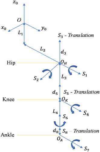
At the knee joint, the gait robot has an active rotational shown by
and a small passive translation (
)
along
which comes from the dampers. Further, at the robot ankle joint, the robot has an active rotational
(
) and a small passive rotation (
). There is also a small passive translation (
) allowed along
due to the damper springs ( and ). Therefore, the proposed gait robot design has eight
out of which three are active and the rest five are passive ones.
Screw theory is used in this research to derive and analyze kinematics of the entire mechanism in place of DH parameters and Euler angles. It simplifies the forward kinematics and doesn’t require link lengths, twists, link offsets etc. shows the directions and the positions of the eight on the gait robot and these parameters are further used in the current positional analysis and to obtain transformation matrices. For eight
there are equal number of transformations which are normally presented by homogenous transformation matrices.
Table 2. Parameters for positional analysis.
Elements of the individual transformation matrices for eight (EquationAppendix) can be obtained using and using the generalized homogeneous transformation matrix Equation(7)
(7)
(7) .
(7)
(7)
Table 3. Elements of the generalized homogeneous transformation matrix.
Transformation matrices are important to carry out the kinematic analysis which is of two kinds, namely, forward kinematics (FK) and inverse kinematics (IK). In order to achieve the desired position/velocity of a joint, it is required to know its current positional/velocity from known position/velocity of the preceding joints. Obtaining position/velocity of a successive joint of an open chain in space using known position/velocities of all preceding joints
is termed as forward kinematics Equation(8)
(8)
(8) . Later, to move successive joints to different position/velocity in space, we need to figure out the required position/velocities of all the preceding joints from the known position/velocity of the successive joints and this is done using the inverse kinematic analysis Equation(9)
(9)
(9) . If
are the position and velocity of
successive joint and
are the positions and velocities of all the preceding joints, the forward kinematics and the inverse kinematics can be expressed mathematically as (8, 9).
(8)
(8)
(9)
(9)
5.2. Forward kinematic analysis
For an open chain mechanism, forward kinematics always provides closed-form solutions since this is an Injective function. In the present case, the overall mechanism has eight and, therefore, the homogeneous transformation matrix used to perform forward kinematic analysis is given by Equation(10)
(10)
(10) .
(10)
(10)
Homogeneous transformation matrices for individual is provided in the Appendix for reference whereas the elements of the homogeneous transformation matrices Equation(8)
(8)
(8) are listed in (Appendix) in terms of their corresponding angular displacements. Fourth row elements of Equation(8)
(8)
(8) are taken as
since the motions are transformed without scaling.
Table 4. Elements of the homogeneous transformation matrix Equation(8)(8)
(8) .
5.3. Inverse kinematic analysis
The inverse kinematics (IK) is performed to find positions of preceding joints for given positions of the succeeding joints and related link lengths. Unfortunately, the IK analysis of an open chain mechanism does not provide a closed form solution using the conventional approach (Lloyd, Irani, and Ahmadi Citation2022). In fact, the IK analysis provides more than one solution and to obtain an accurate singular solution, analytical and iterative methods are normally employed (Zhong, Peng, and Dou Citation2022).
However, since FK and IK modules are normally part of the robot closed loop feedback controller, these are executed at higher frequencies. Therefore, apart from accuracy, it is imperative for FK and IK calculations to be computationally efficient. A machine learning based model can be developed to obtain solutions of the inverse kinematics of the gait robot quickly and precisely. In order to develop such a model, a database is normally required for training and testing the model and obtaining optimal model parameters. Solutions from the forward kinematic analysis Equation(8)(8)
(8) can be used for this purpose. During the present research, a database is first created by solving the forward kinematics Equation(8)
(8)
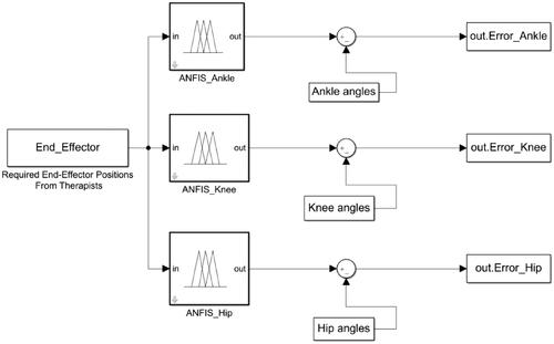
(8) which is an Injective function. Forward kinematics provides positions of the end-effector or a successive joint as outputs for the input preceding joint positions. Since mapping between inputs and outputs for an FK analysis is one-to-one, a database can be prepared which has a value for end-effector position for every set of joint positions. It is possible to develop a machine learning model by training on this database to give joint positions for a given end-effector position. A machine learning based model has been developed next to test how accurately instructions from therapists about gait trajectories can be quickly and precisely translated in terms of ankle knee, and hip joint angles. This information is later given to the controller for further execution. In order to obtain joint angles from the information about end-effector position, a multiple adaptive neuro-fuzzy inference system (MANFIS) has been developed during this research that contains three individual fuzzy inferencing systems (FIS) (FIS_Ankle, etc., shown in ) to provide joint angles at ankle, knee and hip (Kashyap, Parhi, and Pandey Citation2022). This model takes position coordinates of the forefoot containing phalanges as inputs and produces three joint angles through three different ANFIS (adaptive neuro-fuzzy inference system) models and these outputs can be either obtained as three different outputs or as a single vector of three values. Three ANFIS models combined in such a way are called MANFIS (). Details about construction and training of ANFIS are briefly discussed here and readers are further advised to refer (Refaai Citation2022) for more details.
Figure 7. MANFIS-based IK optimization.
5.4. Adaptive neuro-fuzzy inference system (ANFIS)
The adaptive network-based fuzzy inference system (ANFIS) makes use of a ‘hybrid learning’ rule to optimize the fuzzy system parameters of a first order Sugeno system. A first order Sugeno system can be graphically represented by:
The ANFIS architecture for a three-input ( and
position coordinates of the end-effector), first-order Sugeno model is shown in (Jamwal et al. Citation2010). Here, a first order polynomial is used to evaluate rule outputs for a given set of inputs using randomly initiated consequence parameters (
and
) which are later obtained using least square algorithm. The polynomial used for
rule is given as Equation(11)
(11)
(11) :
(11)
(11)
As such there are two sets of ANFIS parameters that are required to create the models and therefore are identified through training and testing over database. The first set of parameters is the antecedent fuzzy parameters (also called as fuzzy membership functions) namely, the mean and the standard deviation since in the present work, Gaussian functions are used to define the fuzzy functions. Later, the set of consequence parameters ( and
) is identified as discussed above. During the present research, Marquardt’s gradient descent algorithm is used to optimize the antecedent parameters (fuzzy parameters) and least squares algorithm is used to solve for the consequent parameters. Such training is termed as hybrid because two very different algorithms are employed to reduce the error. Initially the consequent parameters are updated and then the antecedent parameters are identified by backpropagating the errors.
Figure 8. ANFIS architecture for IK solver.
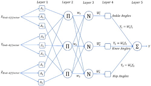
Outputs from the five layered ANFIS architecture () are described below:
Layer 1. Inputs are converted to fuzzy values:
Layer 2. Fuzzy outputs from the rules stored in a variable (
).
Layer 3. Weighted average of the outputs (
Layer 4. Rule outputs are found using the consequent parameters.
Layer 5. Solve using regression to find the consequent parameters as shown below.
Looking at Equation(13)
5. Fuzzy logic controller
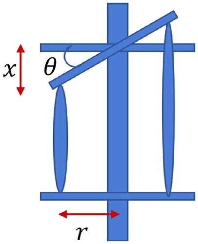
The gait robot is intended to move on prescribed trajectories which are normally provided by the therapists in terms of hip, knee, and ankle angles. Since, PMAs are used in the proposed gait robot, the prescribed angles at various joints can be achieved by controlling lengths of the PMAs. The angular displacements at joints are further achieved by the coupled motion of the PMAs, therefore, a relation is required to be established between input PMA contraction/extension and the output joint angles. Referring , it is apparent that in order to obtain an angular displacement of at a joint the required contraction (
) in PMA can be given by
Eventually, to control robot motions the PMA lengths are required to be controlled by inflating and deflating with appropriate pressures.
Figure 9. Antagonistic PMA actuation and joint rotation.
Owing to the transient and nonlinear behavior of PMAs, in the present work a fuzzy logic controller has been designed to operate the gait robot. The commanded gait robot trajectories are first converted to joint angles which are further converted to the required PMA lengths at different time instances. The fuzzy logic controller is designed, based on authors’ previous work (Xie and Jamwal Citation2011), to control PMA lengths and provide the desired joint angles and thereby the gait trajectories.
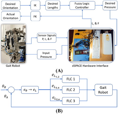
Overview of the Gait Robot hardware is shown in whereas working of the controller is explained using a simplified block diagram in . Commanded trajectory is converted to desired joint orientations and passed through IK module to convert these to the desired PMA lengths. The fuzzy controller provides the pressure values for a pair of muscles to work antagonistically and implement the required change in joint angle. Three instances of similar fuzzy controllers are used for hip, knee, and ankle joints. The dSPACE® card is used to implement the controller and acts as a hardware interface to facilitate reading sensors (pressure, force, and PMA lengths) and writing on the solenoid valves.
Figure 10. (A) Overview of the Gait Robot hardware and (B) Controller schematic.
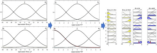
The error in the commanded joint angles is converted into desired change in PMA lengths and given to three fuzzy controllers designed for hip, knee, and ankle joints. The fuzzy controller designed to be used in the overall controller scheme is shown in with further details. The input errors in lengths () are converted to fuzzy variables using gaussian fuzzy functions. The rule base designed to map error in length to appropriate pressure values (
) and give pressure values as output.
Figure 11. Fuzzy controller design showing fuzzy variable and fuzzy rule-base for inferencing output pressure.
6. Evaluation and results
Evaluation and the related results from the MANFIS-based IK solver and the fuzzy controller are discussed in this section. First, in order to evaluate the IK solver, a training database consisting of 60,000 sets of end effector positions obtained using the FK Equation(8)(8)
(8) . Here the input angular positions are from the hip, knee, and the ankle joints. During gait, the required ranges of motions at hip and knee joints are
and
respectively, where extension is considered as positive rotation. Similarly, during walking, the ankle plantarflexion motion is about
whereas the dorsiflexion is normally
(Mena, Mansour, and Simon Citation1981). The database is created by incrementing the three rotations by one degree and so the database has (
) rows with as many end-effector positions which are found using the FK analysis. The database is further divided into training, testing, and validation datasets with 70%, 15%, and 15% data respectively. The sum of squared errors for the test data from the MANFIS model was found to be
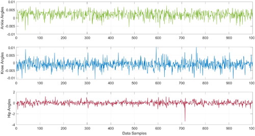
degrees respectively for predicting ankle, knee, and hip joints respectively (). Since the robot link connected at the hip joint has larger rotational inertia, it is subjected to larger deflections compared to the robot links connected at knee and ankle. This fact is apparent from the results in where errors in estimating hip angles are larger compared to the errors in the estimation of ankle and knee joint angles for given positions of the end-effector.
Figure 12. Estimated joint errors using IK solver in ANFIS.
Newton–Raphson method is a popular tool to solve inverse kinematics and in this research results from MANFIS are benchmarked against the results obtained from iterative Newton–Raphson approach (Xu, Wang, and Sun Citation2010). It is known that the N–R method can be computationally intensive since multiple iterations are required to achieve convergence. Further, the selection of the initial solution is also critical for the convergence of this method. While it is possible to address the issue of initializing solutions from previous results, the computational efficiency can only be achieved using more powerful computing hardware. During simulation experiments in the present research, it was found that the N–R method takes 110 milliseconds for 100 IK computations while MANIS-based IK solver took only 2.5 milliseconds for 100 IK computations.
Later, feasibility of the controller () is evaluated conducting experiments with the gait robot and the interfacing dSPACE® hardware. Initially, the controller is commanded to actuate the robot’s hip rotations (in sagittal plane). Position coordinates of the end-effector that are recorded during ‘only hip rotations’ are plotted together with the end-effector velocity and acceleration (). The input hip rotations in the sagittal plane ( plane) resulted into linear motion of the end-effector in
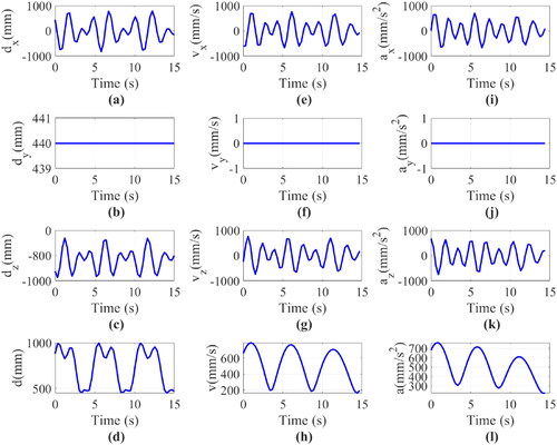
plane, as seen in . Later, the controller is commanded with rotations at robot hip, knee, and ankle joints simultaneously and the resulting end-effector positions are plotted in together with related velocities. End-effector positions ( and ) are compared from the FK and IK modules and found to be correct.
Figure 13. Displacement (a) along x-axis, (b) along y-axis, (c) along z-axis, (d) resultant displacement. Velocity (e) along x-axis, (f) along y-axis, (g) along z-axis, (h) resultant velocity. Acceleration (i) along x-axis, (j) along y-axis, (k) along z-axis, (l) resultant acceleration of the Endpoint (ankle joint) with hip rotation only.
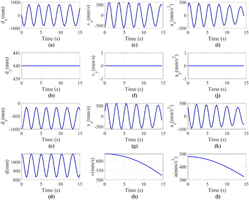
Figure 14. Displacement (a) along x-axis, (b) along y-axis, (c) along z-axis, (d) resultant displacement. Velocity (e) along x-axis, (f) along y-axis, (g) along z-axis, (h) resultant displacement. Acceleration (i) along x-axis, (j) along y-axis, (k) along z-axis, (l) resultant acceleration of the Endpoint (forefoot) with hip, knee, and ankle rotation.
7. Discussion and conclusions
The main goal of this research was to identify vital design and actuation issues of gait rehabilitation robots and propose a new gait robot design that can potentially address these issues. Toward meeting this goal, the first ever design of a multi-DOF gait robot is proposed in this article that has three actuated and five passive degrees of freedom to extend a natural walking experience to the users. The gait robot prototype developed during this research can actuate hip, knee, and ankle joints whereas it also can provide passive motions at the pelvis, hip, and ankle joints. The proposed design allows vertical translation at the pelvis, abduction/adduction and flexion/extension motions at the hip joint, and flexion/extension with small internal-external rotation and abduction-adduction motions at the knee and ankle joints.
The use of PMAs for actuators makes the proposed gait robot intrinsically compliant and thereby safe to be used by human subjects. Actuation amplification has been achieved using a novel mechanism for the gait robot powered by PMAs. This is an important contribution that overcomes the force output limitations for robot exoskeletons powered by PMAs. A self-alignment mechanism for providing better alignment of robot joints with anatomical joints was also achieved using two approaches including the use of rubber bushes and dampers.
To evaluate the design of the gait robot, kinematic analysis was performed. Performing inverse kinematics was not possible following the analytical methods owing to the fact that the gait robot designed is an open chain mechanism. A multiple adaptive neuro-fuzzy inference system (MANFIS) has been developed during this research that contains three fuzzy inferencing systems to provide joint angles at ankle, knee and hip to achieve a target end-effector position. This model takes position coordinates of the forefoot containing phalanges as inputs and produces three joint angles through three different ANFIS models and these outputs can be either obtained as three different outputs or as a single vector of three values. The MANFIS-based IK solver is found to be faster method when benchmarked against Newton-Paphson method.
Later, to move the robot on commended trajectories, a fuzzy logic controller is designed and implemented using appropriate hardware interface. Results from the controller were checked from similar results obtained through the kinematic analysis and found to be comply.
In summary, this article presents a novel design of a gait rehabilitation robot. The gait rehabilitation robot has multiple DOFs powered by PMAs. A novel mechanical amplification system was developed along with the self-aligning mechanism. To the authors’ best knowledge, no prior work including a multi-DOF gait rehabilitation robot powered by PMAs capable of providing self-alignment has been reported in the literature before this work. Future work shall involve the development of an adaptive controller for the gait robot as well as the evaluation of the gait robot with human participants.
References
- Agrawal, S. K., and A. Fattah. 2004. Theory and design of an orthotic device for full or partial gravity-balancing of a human leg during motion. IEEE Transactions on Neural Systems and Rehabilitation Engineering 12 (2):157–65. doi:10.1109/TNSRE.2004.827221.
- Banala, S. K., S. K. Agrawal, A. Fattah, V. Krishnamoorthy, W. Hsu, J. Scholz, and K. Rudolph. 2006. Gravity-balancing leg orthosis and its performance evaluation. IEEE Transactions on Robotics 22 (6):1228–39. doi:10.1109/TRO.2006.882928.
- Beyl, P., M. van Damme, R. van Ham, B. Vanderborght, and D. Lefeber. 2009. Design and control of a lower limb exoskeleton for robot-assisted gait training. Applied Bionics and Biomechanics 6 (2):229–43. doi:10.1080/11762320902784393.
- Brockett, C. L., and G. J. Chapman. 2016. Biomechanics of the ankle. Orthopaedics and Trauma 30 (3):232–8. doi:10.1016/j.mporth.2016.04.015.
- Cao, J., S. Q. Xie, and R. Das. 2018. MIMO sliding mode controller for gait exoskeleton driven by pneumatic muscles. IEEE Transactions on Control Systems Technology 26 (1):274–81. doi:10.1109/TCST.2017.2654424.
- Carlo, A. 2009. Human and economic burden of stroke. Age and Aging 38:4–5.
- Cempini, M., S. M. M. De Rossi, T. Lenzi, N. Vitiello, and M. C. Carrozza. 2013. Self-alignment mechanisms for assistive wearable robots: A kinetostatic compatibility method. IEEE Transactions on Robotics 29 (1):236–50. doi:10.1109/TRO.2012.2226381.
- Chang, M. K. 2010. An adaptive self-organizing fuzzy sliding mode controller for a 2-DOF rehabilitation robot actuated by pneumatic muscle actuators. Control Engineering Practice 18 (1):13–22. doi:10.1016/j.conengprac.2009.08.005.
- Chaparro-Cárdenas, S. L., A. A. Lozano-Guzmán, J. A. Ramirez-Bautista, and A. Hernández-Zavala. 2018. A review in gait rehabilitation devices and applied control techniques. Disability and Rehabilitation. Assistive Technology 13 (8):819–34. doi:10.1080/17483107.2018.1447611.
- Chou, C.-P, and B. Hannaford. 1994. Static and dynamic characteristics of McKibben pneumatic artificial muscles. Proceedings - IEEE International Conference on Robotics and Automation.
- Cieza, A., K. Causey, K. Kamenov, S. Hanson, S. Chatterji, and T. Vos. 2020. Global estimates of the need for rehabilitation based on the Global Burden of Disease study 2019: A systematic analysis for the Global Burden of Disease Study 2019. The Lancet 396 (10267):2006–17. doi:10.1016/S0140-6736(20)32340-0.
- Colbrunn, R. W., G. M. Nelson, and R. D. Quinn. 2001. Modeling of braided pneumatic actuators for robotic control. Proceedings of the International Conference on Intelligent Robots and Systems, Oct 29–Nov 03 2001.
- Festo_Corporation. 2022. Fluidic Muscle DMSP. https://www.festo.com/us/en/p/fluidic-muscle-id_DMSP/.
- Giovacchini, F., F. Vannetti, M. Fantozzi, M. Cempini, M. Cortese, A. Parri, T. Yan, D. Lefeber, and N. Vitiello. 2015. A light-weight active orthosis for hip movement assistance. Robotics and Autonomous Systems 73:123–34. doi:10.1016/j.robot.2014.08.015.
- Gray, H. A., S. Guan, L. T. Thomeer, A. G. Schache, R. de Steiger, and M. G. Pandy. 2019. Three-dimensional motion of the knee-joint complex during normal walking revealed by mobile biplane x-ray imaging. Journal of Orthopaedic Research 37 (3):615–30. doi:10.1002/jor.24226.
- Hogan, N., H. Krebs, B. Rohrer, J. Palazzolo, L. Dipietro, S. Fasoli, J. Stein, R. Hughes, W. Frontera, D. Lynch, et al. 2006. Motions or muscles? Some behavioral factors underlying robotic assistance of motor recovery. Journal of Rehabilitation Research and Development 43 (5):605–18. doi:10.1682/jrrd.2005.06.0103.
- Huang, J., X. Tu, and J. He. 2016. Design and evaluation of the RUPERT wearable upper extremity exoskeleton robot for clinical and in-home therapies. IEEE Transactions on Systems, Man, and Cybernetics: Systems 46 (7):926–35. doi:10.1109/TSMC.2015.2497205.
- Huang, M., X. Huang, X. Tu, Z. Li, and Y. Wen. 2016. An online gain tuning proxy-based sliding mode control using neural network for a gait training robotic orthosis. Cluster Computing 19 (4):1987–2000. doi:10.1007/s10586-016-0629-y.
- Hussain, S. 2014. State-of-the-art robotic gait rehabilitation orthoses: Design and control aspects. NeuroRehabilitation 35 (4):701–9. doi:10.3233/NRE-141174.
- Hussain, S., P. K. Jamwal, P. Van Vliet, and M. H. Ghayesh. 2020. State-of-the-art robotic devices for wrist rehabilitation: Design and control aspects. IEEE Transactions on Human-Machine Systems 50 (5):361–72. doi:10.1109/THMS.2020.2976905.
- Hussain, S., P. K. Jamwal, M. H. Ghayesh, and S. Q. Xie. 2017. Assist-as-needed control of an intrinsically compliant robotic gait training orthosis. IEEE Transactions on Industrial Electronics 64 (2):1675–85. doi:10.1109/TIE.2016.2580123.
- Hyun, D. J., H. Park, T. Ha, S. Park, and K. Jung. 2017. Biomechanical design of an agile, electricity-powered lower-limb exoskeleton for weight-bearing assistance. Robotics and Autonomous Systems 95:181–95. doi:10.1016/j.robot.2017.06.010.
- Jamwal, P. K., and S. Hussain. 2016. Multicriteria design optimization of a parallel ankle rehabilitation robot: Fuzzy dominated sorting evolutionary algorithm approach. IEEE Transactions on Systems, Man, and Cybernetics: Systems 46 (5):589–97. doi:10.1109/TSMC.2015.2478389.
- Jamwal, P. K., S. Hussain, M. H. Ghayesh, and S. V. Rogozina. 2016. Impedance control of an intrinsically compliant parallel ankle rehabilitation robot. IEEE Transactions on Industrial Electronics 63 (6):3638–47. doi:10.1109/TIE.2016.2521600.
- Jamwal, P. K., S. Hussain, N. Mir-Nasiri, M. H. Ghayesh, and S. Q. Xie. 2018. Tele-rehabilitation using in-house wearable ankle rehabilitation robot. Assistive Technology 30 (1):24–33. doi:10.1080/10400435.2016.1230153.
- Jamwal, P. K., S. Q. Xie, Y. H. Tsoi, and K. C. Aw. 2010. Forward kinematics modelling of a parallel ankle rehabilitation robot using modified fuzzy inference. Mechanism and Machine Theory 45 (11):1537–54. doi:10.1016/j.mechmachtheory.2010.06.017.
- Junius, K., M. Degelaen, N. Lefeber, E. Swinnen, B. Vanderborght, and D. Lefeber. 2017. Bilateral, misalignment-compensating, full-DOF hip exoskeleton: Design and kinematic validation. Applied Bionics and Biomechanics 2017:1–14. doi:10.1155/2017/5813154.
- Kapsalyamov, A., S. Hussain, and P. K. Jamwal. 2020. State-of-the-art assistive powered upper limb exoskeletons for elderly. IEEE Access 8:178991–9001. doi:10.1109/ACCESS.2020.3026641.
- Kapsalyamov, A., P. K. Jamwal, S. Hussain, and M. H. Ghayesh. 2019. State of the art lower limb robotic exoskeletons for elderly assistance. IEEE Access 7:95075–86. doi:10.1109/ACCESS.2019.2928010.
- Kashyap, A. K., D. R. Parhi, and A. Pandey. 2022. Multi-objective optimization technique for trajectory planning of multi-humanoid robots in cluttered terrain. ISA Transactions 125:591–613. doi:10.1016/j.isatra.2021.06.017.
- Kim, I., T. Lee, and S. H. Lee. 2021. Ankle intention detection algorithm using electromyography signal. Journal of Computational Design and Engineering 8 (5):1234–42. doi:10.1093/jcde/qwab042.
- Klein, J., S. J. Spencer, J. Allington, K. Minakata, E. T. Wolbrecht, R. Smith, J. E. Bobrow, and D. J. Reinkensmeyer. 2008. Biomimetic orthosis for the neurorehabilitation of the elbow and shoulder (BONES). 2008 2nd IEEE RAS & EMBS International Conference on Biomedical Robotics and Biomechatronics.
- Lloyd, S., R. A. Irani, and M. Ahmadi. 2022. Fast and robust inverse kinematics of serial robots using Halley’s method. IEEE Transactions on Robotics 38 (5):2768–80. doi:10.1109/TRO.2022.3162954.
- Marchal-Crespo, L. 2007. Review of control strategies for robotic movement training after neurologic injury. Journal of NeuroEngineering and Rehabilitation. 14:22–44.
- Mat Dzahir, M. A., and S-i Yamamoto. 2014. Recent trends in lower-limb robotic rehabilitation orthosis: Control scheme and strategy for pneumatic muscle actuated gait trainers. Robotics 3 (2):120–48. doi:10.3390/robotics3020120.
- Mena, D., J. M. Mansour, and S. R. Simon. 1981. Analysis and synthesis of human swing leg motion during gait and its clinical applications. Journal of Biomechanics 14 (12):823–32. doi:10.1016/0021-9290(81)90010-5.
- Otten, A., C. Voort, A. Stienen, R. Aarts, E. v. Asseldonk, and H. v. d. Kooij. 2015. LIMPACT:A hydraulically powered self-aligning upper limb exoskeleton. IEEE/ASME Transactions on Mechatronics 20 (5):2285–98. doi:10.1109/TMECH.2014.2375272.
- Qian, K., Z. Li, S. Chakrabarty, Z. Zhang, and S. Q. Xie. 2023. Robust iterative learning control for pneumatic muscle with uncertainties and state constraints. IEEE Transactions on Industrial Electronics 70 (2):1802–10. doi:10.1109/TIE.2022.3159970.
- Ramirez-Bautista, J. A., A. Hernández-Zavala, S. L. Chaparro-Cárdenas, and J. A. Huerta-Ruelas. 2018. Review on plantar data analysis for disease diagnosis. Biocybernetics and Biomedical Engineering 38 (2):342–61. doi:10.1016/j.bbe.2018.02.004.
- Ramirez-Bautista, J. A., J. A. Huerta-Ruelas, S. L. Chaparro-Cárdenas, and A. Hernández-Zavala. 2017. A review in detection and monitoring gait disorders using in-shoe plantar measurement systems. IEEE Reviews in Biomedical Engineering 10:299–309. doi:10.1109/RBME.2017.2747402.
- Refaai, M. R. A. 2022. An improved inverse kinematics solution for a robot arm trajectory using multiple adaptive neuro-fuzzy inference systems. Advances in Materials Science and Engineering 2022:1–12. doi:10.1155/2022/1413952.
- Reinkensmeyer, D. J., J. L. Emken, and S. C. Cramer. 2004. Robotics, motor learning, and neurologic recovery. Annual Review of Biomedical Engineering 6:497–525. doi:10.1146/annurev.bioeng.6.040803.140223.
- Reynolds, D., D. Repperger, C. Phillips, and G. Bandry. 2003. Modeling the dynamic characteristics of pneumatic muscle. Annals of Biomedical Engineering 31 (3):310–7. doi:10.1114/1.1554921.
- Saccares, L., I. Sarakoglou, and N. G. Tsagarakis. 2016. It-knee: An exoskeleton with ideal torque transmission interface for ergonomic power augmentation. IEEE International Conference on Intelligent Robots and Systems.
- Sarkisian, S. V., M. K. Ishmael, G. R. Hunt, and T. Lenzi. 2020. Design, development, and validation of a self-aligning mechanism for high-torque powered knee exoskeletons. IEEE Transactions on Medical Robotics and Bionics 2 (2):248–59. doi:10.1109/TMRB.2020.2981951.
- Schiele, A., and F. C. T. Van Der Helm. 2006. Kinematic design to improve ergonomics in human machine interaction. IEEE Transactions on Neural Systems and Rehabilitation Engineering 14 (4):456–69. doi:10.1109/TNSRE.2006.881565.
- Stienen, A. H. A., E. E. G. Hekman, F. C. T. v. d. Helm, and H. v. d. Kooij. 2009. Self-aligning exoskeleton axes through decoupling of joint rotations and translations. IEEE Transactions on Robotics 25 (3):628–33. doi:10.1109/TRO.2009.2019147.
- Tondu, B., and P. Lopez. 1995. Theorie d‘un muscle artificiel pneumatique et application a la modelisation du muscle artificiel de McKibben. Theory of an Artificial Pneumatic Muscle and Application to the Modelling of McKibben Artificial Muscle." 320 (3):105–14.
- Tsagarakis, N., and D. G. Caldwell. 2000. Improved modelling and assessment of pneumatic muscle actuators. Proceedings - IEEE International Conference on Robotics and Automation.
- Tschiersky, M., E. E. G. Hekman, D. M. Brouwer, and J. L. Herder. 2019. Gravity balancing flexure springs for an assistive elbow orthosis. IEEE Transactions on Medical Robotics and Bionics 1 (3):177–88. doi:10.1109/TMRB.2019.2930341.
- Wang, D., K. M. Lee, J. Guo, and C. J. Yang. 2014. Adaptive knee joint exoskeleton based on biological geometries. IEEE/ASME Transactions on Mechatronics 19 (4):1268–78. doi:10.1109/TMECH.2013.2278207.
- Weber, L. M., and J. Stein. 2018. The use of robots in stroke rehabilitation: A narrative review. NeuroRehabilitation 43 (1):99–110. doi:10.3233/NRE-172408.
- Winter, D. A. 2009. Biomechanics and motor control of human movement. USA: Wiley Online Library.
- Xie, S. Q., and P. K. Jamwal. 2011. An iterative fuzzy controller for pneumatic muscle driven rehabilitation robot. Expert Systems with Applications 38 (7):8128–37. doi:10.1016/j.eswa.2010.12.154.
- Xu, J., W. Wang, and Y. Sun. 2010. Two optimization algorithms for solving robotics inverse kinematics with redundancy. Journal of Control Theory and Applications 8 (2):166–75. doi:10.1007/s11768-010-0011-1.
- Yao, J., N. Guo, Y. Xiao, Z. Li, Y. Li, F. Pu, and Y. Fan. 2019. Lower limb joint motion and muscle force in treadmill and over-ground exercise. Biomedical Engineering Online 18 (1):89. doi:10.1186/s12938-019-0708-4.
- Young, A. J., and D. P. Ferris. 2017. State of the art and future directions for lower limb robotic exoskeletons. IEEE Transactions on Neural Systems and Rehabilitation Engineering 25 (2):171–82. doi:10.1109/TNSRE.2016.2521160.
- Zanotto, D., Y. Akiyama, P. Stegall, and S. K. Agrawal. 2015. Knee joint misalignment in exoskeletons for the lower extremities: Effects on user’s gait. IEEE Transactions on Robotics 31 (4):978–87. doi:10.1109/TRO.2015.2450414.
- Zhang, J., J. Sheng, C. T. O'Neill, C. J. Walsh, R. J. Wood, J. H. Ryu, J. P. Desai, and M. C. Yip. 2019. Robotic artificial muscles: Current progress and future perspectives. IEEE Transactions on Robotics 35 (3):761–81. doi:10.1109/TRO.2019.2894371.
- Zhong, G., B. Peng, and W. Dou. 2022. Kinematics analysis and trajectory planning of a continuum manipulator. International Journal of Mechanical Sciences 222:107206. doi:10.1016/j.ijmecsci.2022.107206.
- Zhou, L., W. Chen, W. Chen, S. Bai, J. Zhang, and J. Wang. 2020. Design of a passive lower limb exoskeleton for walking assistance with gravity compensation. Mechanism and Machine Theory 150:103840. doi:10.1016/j.mechmachtheory.2020.103840.
Appendix
This section describes the position analysis of the robot from the kinematics perspective.
The gait robot discussed here is an open chain mechanism or a serial robot consisting of the hip, knee, and ankle joints. The overall positioning system used for robot joints is shown in with reference positions on a natural vertical attitude. Point is referred to as the left-top corner of the pelvis part with the
directions of the reference coordinate system shown in .
is referred to as the vertical dimension between Point
and the left hip joint in the design, while
is represented as the width of the gait robot (distance between two hip joints).
is the length of the thigh segment on the robot (distance between hip and knee joints) and
is the shank length (distance between knee and ankle joints).
to
represent the motion of joints depending on the degrees of freedom on designed joints.
and
are translational motions facilitating the self-aligning of robot and human joints in the designed prototype.
Screw theory is used to derive forward and inverse kinematics. showed the parameters used in the current positional analysis. Three coordinates in column represented by
and
respectively and refer to the type of motions each joint can achieve (). Further,
and
describe the positions of joints relative to the global coordinate system. These parameters will be used in equations of screw theory for obtaining transformation matrices.
The elements described in are used for calculating each element in eight homogenous transformation matrices to be used for the eight joints. Here, stands for cos
and S
is used in place of Sin
Parameters in are substituted into relations provided in to derive transformation matrices. While calculating the value of
is considered to be zero. The homogenous transformation matrices
to
are expressed as (EquationA1
(A1)
(A1) – EquationA8
(A8)
(A8) ).
(A1)
(A1)
(A2)
(A2)
(A3)
(A3)
(A4)
(A4)
(A5)
(A5)
(A6)
(A6)
(A7)
(A7)
(A8)
(A8)