
 ?Mathematical formulae have been encoded as MathML and are displayed in this HTML version using MathJax in order to improve their display. Uncheck the box to turn MathJax off. This feature requires Javascript. Click on a formula to zoom.
ABSTRACT
Hydrogen has the potential to be the sustainable fuel of the future, decrease the global dependence on fossil fuel resources, and lower the pollutant emissions from the transportation industry. In this study, recent development in hydrogen-based transportation engines is reviewed to scrutinize the feasibility of using hydrogen as a major fuel of future. Using hydrogen in internal combustion engines achieves only 20-25% efficiency and low power output compared to fossil-fueled internal combustion engines. Although hydrogen-based internal combustion engines have recently received considerable interests, several practical barriers have prevented the fast development of this technology. Hence, at the current stage, using hydrogen as an additive to hydrocarbon fuel systems have been taken into consideration to produce higher performance than hydrogen-only internal combustion engines. Using the dual-fuel strategy can increase the combustion stability and thermal efficiency while decreasing the CO and unburned hydrocarbons emissions, and fuel consumption. Alternatively, hydrogen can be used in fuel cells for vehicular applications with several automotive manufacturers producing fuel cell vehicles currently. Fuel cells can achieve efficiencies of up to 60%, while the rest is lost as heat. Strategies that have been investigated to increase the efficiency, performance, and lifespan of fuel cells are capillary pumping systems, a chemisorption chiller, nanofluids and supercapacitors. All such strategies improved the fuel cells in one or more ways. Safety, hydrogen delivery, onboard storage, and the capital and operating costs of hydrogen powered vehicles are analyzed to approach to clean transportation utopia.
1. Introduction
The most significant problem of the 21st century is the global demand for enhanced energy generation and the related environmental issues such as local pollution and global warming. In 2016, it was internationally agreed that 2°C of global temperature increase is inevitable (Álvarez Fernández et al. Citation2018). This limit means that the design goals for the energy system must be widened from only concerning technology and economics to including environmental impact, sustainability through its life cycle, constituent materials, and the waste products (Hosseini Citation2019). A significant amount of the energy consumed globally is by transportation vehicles and machineries which are almost exclusively dependent on fossil fuels (Chapman Citation2007; Mori and Hirose Citation2009). Due to fossil fuel resources depletion and increasing rate of anthropogenic greenhouse gas (GHG) emissions, the possibility of using other prime movers and energy carriers is highlighted by energy strategists and environmentalists (Hosseini and Wahid Citation2012). Currently, around 65% of the worldwide energy demand is supplied by fossil fuels in fluid form because they are easily accessible and convenient to use. In the urban transportation (private cars, taxis, buses, and urban rail transit), the energy consumption of various options is different, with private cars having the highest energy consumption. The rapid development of the private cars industry has an adverse influence on the energy scenario and environment of the cities (Chang, Ma, and Wu Citation2018). Road vehicles consume approximately 50% of the world’s oil produced (Balat Citation2008). The demand for crude oil has continuously increased because of economic acceleration. Energy planners of many countries are searching for sustainable solutions to fulfill their energy demand, especially in the transportation sector (Hosseini et al. Citation2013). In this context, research and investments in the utilization of renewable and sustainable alternative fuels, as well as the enhancement of energy efficiency of the engines have been developed (Hosseini and Wahid Citation2014). Hydrogen is one of the most important candidates to supply energy demands in future and plays a crucial role in most governmental strategic plans (Elnashaie, Chen, and Prasad Citation2007; Hosseini, Wahid, and Ganjehkaviri Citation2015b). Hydrogen has a heating value three times larger than petroleum, on a mass basis, and creates significantly less zero harmful tailpipe-emissions in internal combustion engines and fuel cells, which is one of the most significant drawbacks of fossil fuels (Fayaz et al. Citation2012; Muradov and Vezirolu Citation2005).
There are countless benefits to using hydrogen instead of fossil fuels. The most notable benefits are that it is considered as an environmentally friendly fuel because it emits only H2O when used in a fuel cell (Zeng and Zhang Citation2010). Hydrogen, the most plentiful element, has the highest specific energy content compared to the fossil fuels (Balat and Balat Citation2009). Hydrogen possesses an energy yield of 122 kJ/g, which is 2.75 times larger than numerous hydrocarbon fuels (Kapdan and Kargi Citation2006). Energy per unit mass stored in hydrogen is about 2.6 times more than gasoline; however, hydrogen is disadvantageous because it requires approximately four times more volume for storage than gasoline when stored as a liquid, and approximately 19 times more volume when stored as a gas (Petkov, Veziroǧlu, and Of Citationn.d.). Utilizing hydrogen as a fuel in an internal combustion engine (ICE) or fuel cell (FC) propelled vehicles is a promising direction for the future of the transportation sector. Hydrogen-fueled ICEs (H2ICEs) have low achievable efficiency of 20–25%, which is a cause for problems when considering the current hydrogen storage capabilities in both gas and liquid states. Lacking the ability to achieve driving ranges comparable to those of fossil-fueled ICE vehicles makes H2ICEs less appealing to consumers. The poor efficiency of H2ICEs and low storage capabilities combined with the lack of hydrogen refueling infrastructure makes the engine type not feasible for consumers at this time. Studies have investigated methods of improving the efficiency of hydrogen ICEs to make the application of hydrogen in ICE vehicles feasible for light- and heavy-duty vehicles. To supplement the low storage capabilities of hydrogen, some studies have investigated the use of dual-fuel fossil fuel-hydrogen ICEs. On the other hand, hydrogen FC vehicles offer more potential with the current efficiency of up to 60%; however, the use of rare-earth metals in different types of FCs increases the cost and creates a limiting factor on the manufacturability (US Department of Energy Citation2017a). Certain types of membranes used in fuel cells are subject to damage from using less-than-pure quality hydrogen, which shortens the lifespan of the fuel cell stack. Studies have been conducted on improving the operation and increasing the efficiency in order to improve the durability and lifespan of FCs. A hydrogen-based transportation system would drastically alter the fuel production industry and introduces several new economic challenges and opportunities (Chen et al. Citation2019).
Several experimental methods to produce hydrogen (hydrogen from wind energy (Nagasawa et al. Citation2019), solar energy (Burhan et al. Citation2017), biomass (Hosseini et al. Citation2015a), geothermal (Kianfard, Khalilarya, and Jafarmadar Citation2018), nuclear energy (Sorgulu and Dincer Citation2018), dissociating water by electrolysis (Dos Santos et al. Citation2017), fossil fuels (Lee, Elgowainy, and Dai Citation2018a), etc.) have been investigated, but the majority of hydrogen is generated from costly, nonrenewable sources (Holladay et al. Citation2009). A variety of clean/highly efficient methods have been developed to convert the chemical energy of hydrogen to a desirable energy type (fuel cell (Das et al. Citation2017), gas turbine (Ditaranto, Li, and Løvås Citation2015), internal combustion engine (ICE) (Yang et al. Citation2018), etc.) (Hosseini and Wahid Citation2016). The annual hydrogen production is estimated to be about 50 million tons; where the share of natural gas (NG), oil, coal, and renewable energy sources is 48%, 30%, 18% and 4%, respectively (Srinivasan Citation2006). Electrolysis is a production method that can use renewable energy, but it is an energy extensive process, making it not ideal for sustainable use at this time (Hwang Citation2013). Hydrogen is a clean, versatile, and efficient fuel if it is produced from any of the variety of renewable energy sources and methods; however, only a few of these methods are currently commercially viable (Barbir Citation2009). Presently, the price of hydrogen is more than double that of diesel and petrol on a mass basis. To enable hydrogen production to be environmentally sustainable and competitively priced, substantial progress must be made. To establish an operational hydrogen economy, the required energy for pure hydrogen production, its storage and transport should be estimated (Herzog and Tatsutani Citation2005).
Although very low density of hydrogen has made some challenges for its bulk storage, as well as its distribution and onboard vehicle storage, the advantages of hydrogen utilization in the transportation system are significant enough to introduce hydrogen as a serious energy carrier candidate for modern transportation systems (Verhelst and Wallner Citation2009). Renewable energy can provide hydrogen locally; however, they are not adequate sources to provide enough hydrogen to meet the global requirement (Lindorfer et al. Citation2019). This is because there are currently no adequate storage solutions for hydrogen that are inexpensive. According to the US Department of Energy (DOE), solar is most likely the only source of renewable energy that could produce sufficient hydrogen to develop the hydrogen economy (Edwards et al. Citation2008).
Due to the several challenges in hydrogen production and utilization processes, investigation about development and various characteristics of hydrogen, especially in the transportation engines application, has become one of the most significant research directions. Hence, in this paper, recent developments in hydrogen-based transportation engines with special focus on ICEs and fuel cell vehicles (FCVs) is reviewed to evaluate the feasibility of a hydrogen-based transportation system.
2. Hydrogen transportation engines
Two main hydrogen-based technologies have been employed to power vehicles: hydrogen fuel cell (HFC) (Ehsani et al. Citation2018), and hydrogen-fueled internal combustion engine (H2ICE) (Boretti Citation2011). The benefits of hydrogen FCVs are the high efficiency, the lack of harmful emissions (water vapor is the only emission which is harmless compared to the emissions created by the fossil fuels combustion, such as nitric oxide, nitrogen dioxide, carbon dioxide, and sulfur dioxide), they operate quietly, and are modular (Dicks and Rand Citation2018). FCVs use electrochemical reactions to produce electricity from hydrogen and oxygen. Alternatively, the benefits of H2ICEs are the reliance on a mature industry with a huge production infrastructure, the ability to offer “flex-fuel” to aid in the transitional period which could aid in the deployment of the hydrogen infrastructure, lower requirements for hydrogen compared to HFCs, ultra-low emissions, raised peak and part load efficiencies in comparison with conventionally fueled ICEs, and they are not dependent on rare materials (Verhelst Citation2014). FCVs and battery-electric vehicles (BEVs) use rare materials which could limit the spread of these devices. FCs require platinum, which is already expensive and will increase in price as the demand raises. BEVs use rare earth elements that would be difficult to produce in large quantities. It is estimated that FCVs are capable of reducing greenhouse gas (GHG) emissions by 80% in the US in 2100 compared with that of 1990, and the country will become independent of gasoline fuel in the transportation system by the 2100s (Dougherty et al. Citation2009). An extensive amount of progress has been made in hydrogen ICE vehicles and hydrogen FCVs in the past century. The current hydrogen-fueled vehicles available on the market and some of the most innovative test engines have been compared to the most environmentally friendly fossil-fueled vehicles available today in .
Table 1. Comparisons of the most important engine characteristics for current experimental and developed engine technologies.
3. Challenges in hydrogen powered vehicles
3.1. Safety of hydrogen vehicles
Fuels with low density, high diffusion coefficient, and higher specific heat are safer. The higher specific heat alleviates the temperature mitigations for a given heat input (Singh et al. Citation2015). For a specific fuel, some characteristics like wider ignition limits and lower ignition temperature cause the fuel to become less safe by increasing the limits in which a fire could occur. Higher emissivity/temperature of the flame and high explosive energy make the fuel less safe because the fire will be more damaging [8]. summarizes the fire hazard properties of gasoline, methane, and hydrogen (Veziroğlu and Şahi˙n Citation2008).
Table 2. Fire hazard of various transportation fuels (Veziroğlu and Şahi˙n Citation2008).
Hydrogen is very light (~6.9% density of air), 4 times as diffusive as NG, and 12 times as diffusive as gasoline; hence, a risk of combustion or explosion is minimal (Sharma and Ghoshal Citation2015). Due to the non-toxicity characteristic of hydrogen, its leakage would not damage the environment. An explosion of hydrogen is very difficult to create, so it is much more likely that a quick burning fire would result if a hydrogen/air mixture experienced a spark (Hawkins and Hughes Citation2006). A safety advantage of hydrogen is that it blazes with little heat radiation, therefore only things immediately next to the flame would burn (Alazemi and Andrews Citation2015). The clear flame can also not sear skin at a distance due to its low thermal radiation. Hydrogen can burn in lower concentrations which causes safety concerns (Midilli et al. Citation2005).
The US DOE has set parameters for storage and system safety. For permeation and leakage, the system must fulfill SAE J2579 for system safety; for toxicity, the system must meet applicable standards; and failure analysis must be conducted and evaluated for the system. The permeation and leakage tests are for the entire storage system, rather than each component or storage material. The toxicity criteria are regulated by government standards such as the EPA’s Toxic Substances Control Act Chemical Substance Inventory (TSCA Inventory) and the US Department of Labor Occupational Safety and Health Administration (OHSHA). The safety instructions cover the transport system, manufacture, certification and operation of vehicles, fuel dispensing, and end of life issues, which each must comply with applicable federal, state, and local standards. The onboard storage systems should comply with SAE J2579 and the United Nations Global Technical Regulation No. 13 and the applicable standards for the country that the vehicle is deployed.
3.2. Hydrogen storage tank
There are several levels of hydrogen storage that are required to develop a successful hydrogen economy: at production centers, at filling stations, onboard vehicles, and nationally as a strategic reserve. The storage of hydrogen is the most difficult challenge associated with the hydrogen economy (Chang et al. Citation2016). Before a hydrogen transportation economy can be built, an appropriate storage system must be developed for hydrogen powered vehicles. Due to hydrogen’s extremely low density, a huge onboard storage tank would be needed to transport the fuel. To mimic the 400 km range of a standard car, only 8 kg of hydrogen is required for an ICE or 4 kg of hydrogen for an FC (Schlapbach and Züttel Citation2010). The challenge at hand is finding a material for the storage container that fulfills three requirements: high hydrogen density, fast release/charge kinetics with minimum energy barriers to hydrogen release and charge, and reversibility of the release/charge cycle at moderate temperatures (70–100°C) must be compatible with the FCs. The tank material must have strong chemical bonds and close atomic packing. The material also needs loose enough atomic packing to assist fast diffusion of gaseous hydrogen between the surface and the bulk. An adequate thermal conductivity of the material is required to hamper decomposition by the heat released upon hydrating (Sharma and Ghoshal Citation2015). Investigations show that several materials can meet two of the requirements, but none have been found that fulfill all the necessary requirements. Whichever material is selected must also be cost effective, a practical weight, have an adequate lifetime, and meet safety requirements (Hydrogen Fuel: Production, Transport, and Storage, Citation2008; Satyapal et al. Citation2007). The gravimetric and volumetric density in a storage tank material is very important in both mobile and stationary applications of gaseous hydrogen (Atkinson et al. Citation2001). Carbon nanotubes have been discovered to be a source of hydrogen storage, which spurred a massive influx of research devoted to nanostructures (Hirscher et al. Citation2001). By physio-chemical or chemical treatments, the state of hydrogen can be changed and it can be stored in solid or liquid phases (Dalai et al. Citation2014). Various materials such as boron compounds (Fakioğlu, Yürüm, and Nejat Veziroğlu Citation2004), chemical hydrides (Biniwale et al. Citation2008), carbon-based materials (Xu et al. Citation2007), Mg-based alloys (Jurczyk et al. Citation2008), and metal hydrides (Muthukumar, Prakash Maiya, and Murthy Citation2005; Sakintuna, Lamari-Darkrim, and Hirscher Citation2007; Xiao et al. Citation2008) have been employed in hydrogen storage systems to achieve the best performance.
There are six different methods for storing hydrogen (Züttel Citation2004):
Liquid hydrogen in cryogenic tanks (at 21 K)
Absorbed on interstitial sites in a host metal (at ambient temperature/pressure)
Chemically bonded in covalent and ionic compounds (at ambient pressure)
High-pressure gas cylinders (up to 800 bar)
Adsorbed hydrogen on materials with a large specific surface area (at T < 100 K)
Oxidation of reactive metals (i.e. Li, Na, Mg, Al, Zn) in water.
In the gaseous state, hydrogen has extremely low density (0.09 kg/NA m3), and very low boiling point (20.2 K); however, in liquid phase, the density of hydrogen is exceptionally high (70.9 kg/NA m3) (Balat Citation2008). These properties make storing hydrogen very complicated in mobile application. The current method for storing hydrogen in transportation engines is as a liquid in cryogenic reservoirs (at 20 K) or as a gas in high-pressure cylinders (at up to 700 bar). Neither of these two methods are exceptionally efficient. Compressing the gaseous hydrogen uses up to 20% and liquefying hydrogen requires up to 40% of the energy content. Solid-phase hydrogen storage is compatible with electrolyzers and FCs. A porous material can absorb hydrogen molecules, but generally, an attractive capacity can only be obtained at cryogenic temperatures. The most commonly used material for solid-state hydrogen storage is interstitial metal hydride. Metals are the only reversible solid-phase hydrogen storage that have been commercialized, primarily for stationary applications.
The available tanks for FCVs to the public utilize compressed hydrogen carbon-fiber Type IV tanks that store about 5%wt when pressurized at a global standard of 700 bar. Bus fuel tanks are generally 350 bar composite tanks since energy density is less important in larger vehicles. Another type of compressed hydrogen tank is the composite Type III tanks (Lee et al. Citation2018b). The tanks are composed of an aluminum liner wrapped in epoxy resin-coated, aerospace-grade carbon fiber. The aluminum liner does not have any seams, is more tolerant to impacts than traditional gas tanks, is resistant to heat, can be filled in all weather conditions, fills as quickly as a gasoline tank, has a burst safety factor of 3.0, and has a built-in leak-before-burst fatigue failure design. Liquid hydrogen is compatible with electrolyzers and FCs, but the complexity and cost of a cryogenic liquefier make it impractical for small-scale use; therefore, storing hydrogen in liquid form at low pressures is commonly employed for bulk hydrogen storage and transport (Zhang et al. Citation2005). Currently, limited development has been made for onboard liquid hydrogen fuel tanks for automotive use (Salvi and Subramanian Citation2015). The least expensive technique for creating high-performance composite fuel tanks is filament winding (Vasiliev and Morozov Citation2001). Cold (sub-ambient but higher than 150 K) or cryogenic (below 150 K) storage methods are being investigated because higher fuel density can be achieved at reduced temperatures (“Physical Hydrogen Storage | Department of Energy,” Citationn.d.). Ahluwalia et al. (Ahluwalia, Hua, and Peng Citation2012) claimed that the cryo-compressed storage system is the best storage method at this point because it met all the storage targets for well-to-tank efficiency, well-to-engine efficiency, emissions on a per kilogram of hydrogen basis and on a per mile basis, refueling cost, and ownership cost, but not initial cost and onboard efficiency.
Paster et al. (Paster et al. Citation2011) studied GHG emission, energy efficiency, the well-to-wheel costs and performance of five hydrogen storage techniques. The five systems were cold, compressed gaseous hydrogen at 500 bar and 200 K; cryo-compressed liquid hydrogen (CcH2) at 275 bar and 30 K; compressed gas hydrogen at 350 bar; compressed gas hydrogen at 700 bar; and metal hydride sorbent metal-organic frame work (MOF 177) at 250 bar and 100 K. From this study, the most attractive storage system was determined to be the CcH2 system due to its low price since it runs at lower pressures than the compressed gas systems, used a smaller tank, and can fulfill the DOE’s volumetric efficiency goal even though this system had the highest GHG emissions, hydrogen cost, and energy use. For all five storage methods, the GHG emissions are largely dictated by the method used to produce the hydrogen. The systems that utilized liquid hydrogen required significantly more energy to convert the gaseous hydrogen into a liquid state, thus these systems also have higher GHG emissions.
Refueling compressed gaseous hydrogen tanks takes no more than 5 min, which is comparable to gasoline. DOE Fuel Cell Technologies Office (FCTO) is currently deploying safe, low cost and high-performance storage systems that support a driving range of more than 300 miles (US Department of Energy Citation2017b). The technical system targets that FCTO has set for onboard hydrogen storage systems in light-duty FCVs is shown below in .
Table 3. Technical system targets: On-board hydrogen storage for light-duty FCVs (US Department of Energy Citation2017b).
By 2020, there will be 100 hydrogen refueling stations constructed in California. The targets are set to assure the initial and operational costs of the storage system is comparable to the incumbent technology by 2020.
The most favorable method of hydrogen storage is physical containment, specifically compressed tanks, because they are readily available (Jorgensen Citation2011). The fill time of these tanks is competitive with fossil fuels when the hydrogen is pre-cooled (Maus et al. Citation2008). Cost is the main setback for the wide scale use of compressed hydrogen (CH2) tanks because the material and assembly are expensive. Another potential setback is the public’s concern of using such high pressure (70 MPa) storage tanks in vehicles. An alternative to traditional CH2 tanks that is still being researched is a tank with an internal skeleton, which is a complex design of struts in tension within the tank to resist the forces of the compressed hydrogen (Aceves et al. Citation2006). Liquid hydrogen (LH2) storage has improved significantly, achieving the best specific mass (15%) of other onboard hydrogen storage systems (Fieseler and Allidiers Citation2006). Energy efficiency is decreased when liquid hydrogen is used. To widely develop LH2 systems, the boil off property should be improved. A promising alternative design is a cryo-compressed tank in which hydrogen is highly compressed at cryogenic temperatures. More studies must be done on this method to determine long-term durability and public acceptance of the system. Hydride storage systems require substantial research and progress to meet the requirements for large-scale use. The most well studied hydride is NaAlH4, but it does not have the capacity necessary for application. Based on the results of the few studies, it is indicated that tanks with no internal heat transfer elements could be constructed based on the moderate heat of absorption of hydrogen on surfaces (Paggiaro et al. Citation2010).
Cold hydrogen must be used in this system to double as the fuel and the coolant. High surface area, low-density powders are used in absorption storage systems. The storage media must be compressed into pellets or pucks to increase the amount of media in the tank, but this decreases the specific hydrogen capacity of the media. The system mass and cost are reduced by decreasing the system’s volume and compressing the media, which makes up for the lost capacity. Hydrogen stored via reactive chemicals usually involves borohydride hydrolysis which is a method of fast hydrogen production. This method for use on transportation engines is limited by the high level of heat generation during the reaction, high energy needed to recycle boron oxide and hydroxide by products, and the severe wear on parts in contact with the borohydride solution. Progress has been made in organic liquid carriers which have lower temperature reactions and higher hydrogen capacity than other chemical storage systems (Hovland et al. Citation2003).
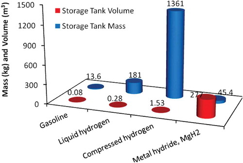
Hydrogen storage requires extensive research and a major technological breakthrough to develop alternative methods to compressed and liquefied hydrogen (Aasadnia and Mehrpooya Citation2018). There are various types of materials for solid-state hydrogen storage that have higher energy density than liquid hydrogen, but extensive investigations are required to ameliorate the materials hydrogen desorption and absorption characteristics. In future, the widely used hydrogen storage method could be solid materials that either chemically bind or physically absorb hydrogen at a greater volume density than LH2 (Zhou Citation2005). demonstrates a comparison between different onboard hydrogen storage systems with respect to volume-mass of fuel sufficient for 418 km of vehicle operation. According to this figure, the storage tank mass of compressed hydrogen is very high, which limits the suitability of this method; however, the stored mass of metal hydrides is low, while the storage system volume is high (xPetkov, Veziroǧlu, and Of Citationn.d.).
Figure 1. On-board hydrogen storage with respect to volume-mass (Petkov, Veziroǧlu, and Of Citationn.d).
3.3. Hydrogen transport and delivery
A successful hydrogen-based transportation system needs infrastructure to deliver hydrogen from production plants to refueling stations (Grüger et al. Citation2018). The potential hydrogen delivery methods are compressed gas pipelines, cryogenic liquid trucks, and compressed tube trailers (Yang and Ogden Citation2007). Any combination of these methods could be utilized at varying stages of the hydrogen automotive transportation. Delivery distance and the number of stations are the crucial factors affecting the cost of delivering hydrogen (Yang, Nicholas, and Ogden Citation2006). Pipelines could be used for transporting hydrogen farther distances, while trucks carry smaller amounts shorter distances. Due to the low density of hydrogen, transportation of liquid or pressurized hydrogen is inefficient (Lasn and Echtermeyer Citation2014). High-purity stainless steel piping with a maximum hardness of 80 HRB is preferred for pipelines (Cadwallader and Herring Citation1999). The lowest cost choice depends upon market and specific geographical characteristics. For the past 50 years, pipelines have been used to transport hydrogen. Currently, there are approximately 16,000 km of hydrogen pipelines throughout the world that transfer hydrogen to chemical plants and refineries (Ball and Wietschel Citation2009). Although the capital cost of pipelines is high, their operation cost is low especially for compressor power. Liquid hydrogen could be transported on ships, railcars or trucks, but its operating cost is very high because of the electricity required for liquefaction (about 30–60% of the total liquefaction costs), which may leave a considerable carbon footprint. Distance is an important factor to select the hydrogen delivery method. Investments in the construction of pipelines of high-quality materials must be made due to the specific physical and chemical characteristics of hydrogen (Ball and Weeda Citation2015).
4. Hydrogen-fueled internal combustion engines
The transportation system is heavily reliant on ICEs, which consume huge amounts of liquid fossil fuels in the form of diesel and gasoline. The energy conversion of petroleum fuel in ICEs via combustion releases various pollutants such as carbon monoxide (CO), nitric oxide (NOx), unburned hydrocarbons (UHCs), particulate matter (PM) and GHGs (Reitz Citation2013). Compared to gasoline engines, the high energy content of H2ICEs combined with their physical and chemical properties allow these engines to operate more effectively on excessively lean mixtures. Hydrogen has greater diffusivity, much lower ignition energy (0.02 MJ), and higher ignition temperature compared to the other fuels (Schlapbach and Züttel Citation2010). Hydrogen possesses greater dispersion in air than gasoline, which is majorly accredited to the ease constitution of a uniform air/fuel mixture, and the rapid dispersion of hydrogen when a leak develops. Because of the low density of hydrogen, two main issues arise when it is used in ICEs. First, to give the vehicle the ability to drive an adequate range, a large storage volume is required. Second, the power output is mitigated by the energy density of the hydrogen/air mixture (Balat Citation2008).
In recent decades, many investigations have been performed to find adequate substitutions for ICEs in transportation systems; however, none of those efforts have yet succeeded in challenging the dominant role of fossil-fueled ICEs. Nevertheless, innovative techniques have been proposed to improve ICEs efficiency and emission characteristics to meet the ever-rising challenges of environmental crisis and petroleum demand (Yan, Xu, and Wang Citation2018).
4.1. Hydrogen-only ICEs
Since the octane number of hydrogen is higher than that of gasoline fuel, it can be considered as a serious candidate to use in IC transportation engines. Some hydrogen properties, such as its higher diffusivity compared to gasoline and methane, lower ignition energy requirement, and higher flame velocity are desirable for spark ignition (SI) engines (Luo and Sun Citation2016). Since hydrogen flame speed is approximately five times higher than gasoline and methane and ten-times higher than diesel, hydrogen-fueled SI engines can be run with lower cyclic variations (Bradley et al. Citation2007).
Hydrogen in SI engines is used in one of the following ways (Acar and Dincer Citation2018):
Manifold induction: Low-temperature hydrogen is injected to the manifold via a passage which is controlled by a valve.
Direct introduction: A cryogenic cylinder is used to store hydrogen. A pump sends the liquid hydrogen to a heat exchanger to evaporate it and then cold hydrogen gas is injected into the engine. By using cold hydrogen gas, pre-ignition is avoided and NOx formation in the combustion process is reduced.
Hydrogen addition to gasoline: In this method, a hydrogen-gasoline mixture is introduced to the ICE where the compressed mixture is ignited by a spark.
Hydrogen also can be employed in a compression ignition (CI) engine. The generated power from a CI engine has been found to be twice that of the same engine worked in the premixed system (Ganesan Citation2012). In hydrogen-based CI motors, an injector is used to inject high-pressure hydrogen into the cylinder (Naber and Siebers Citation1998). Therefore, not only the design of engine structure is important, but the design of the injector is crucial because the injection nozzle controls how the pressurized hydrogen is injected into the system (Gomes Antunes, Mikalsen, and Roskilly Citation2009). Hydrogen supply in CI engines has illustrated significant reductions in CO2, CO, HC and smoke levels that under optimum circumstances can reach as much as over 50%. An apparent effect of using high amounts of hydrogen in IC engines (high load conditions) is a sharp rise in heat release rate (and consequently the increased in-cylinder temperatures and high rates of NOx formation) and brake thermal efficiency (Dimitriou and Tsujimura Citation2017).
Szwaja and Grab-Rogalinski (Szwaja and Grab-Rogalinski Citation2009) used pure hydrogen in homogeneous charge compression ignition (HCCI) engine. To achieve hydrogen auto-ignition under the HCCI mode, a compression ratio of at least 16 was used. It was found that using a stoichiometric hydrogen–air mixture in the HCCI mode generates an extremely high combustion knock. Therefore, various methods such as leaning combustible mixture or EGR should be employed to reduce the knock effect.
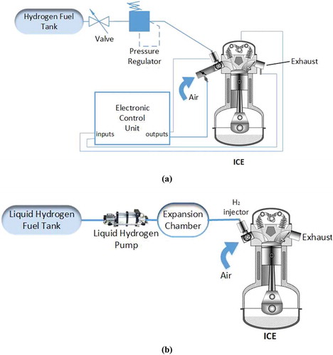
In the pressure-boosted H2ICE structure, a hydrogen gas compression chamber is used to raise the intake-air/hydrogen pressure to maximize engine power density of ICEs. In this condition, the hydrogen pressure is increased to achieve hydrogen volumetric efficiencies closer to the gasoline fuel (White, Steeper, and Lutz Citation2006). Using liquid hydrogen is another method which does not require significant changes in conventional ICEs. In this system, liquefied hydrogen is injected to an expansion chamber to convert to a cold hydrogen gas and ultimately it is conducted to the combustion chamber. Using cold hydrogen decreases NOx emission as well as pre-ignition (Gurz et al. Citation2017). shows these two types of H2ICEs.
Figure 2. Schematic of (a) Pressure-boosted H2ICE (b) Liquid hydrogen internal combustion engine (Gurz et al. Citation2017).
Currently, direct injection (DI) and PFI are the injection methods being investigated for H2ICEs. DI offers high efficiencies and controlled emissions, but the durability of DI injectors is low. Injection needs high pressure, which further limits the storage options. Hydrogen could be stored in cryogenic tanks in the liquid state and injection pressure are generated onboard, or compressed hydrogen is stored, which limits the tank capacity and onboard compression would negate the efficiency benefits of DI (Peschka Citation1998).
Numerous labs and organizations have been conducting research in direct injection for hydrogen fuels. The DOE program targeted demonstrating a peak brake thermal efficiency (BTE) of 45%, a part-load BTE of 31% with part load point set at 2 bar brake mean effective pressure (bmep) at 1500 rpm, and “Tier II Bin 5” emissions (which limit NOx emissions to 0.07 g/mile) (FreedomCAR and Fuel Partnership Plan -March 2006). The National Traffic Safety & Environment Laboratory (NTSEL) project aimed a peak power output of 100 kW from a 4-cylinder naturally aspirated engine with less than 0.05 g/kWh of NOx on a JE05 transient emission testing cycle.
Sopena et al. (Sopena et al. Citation2010) modified an SI gasoline-fueled ICE of a transportation vehicle (suitable for both interurban and city) to operate on hydrogen fuel only. The most important modifications were performed on the electronic management unit, gas injectors, inlet manifold, and oil radiator. Verhelst and Sierens (Verhelst and Sierens Citation2001) upgraded a GM/Crusader V8 engine from fossil fuels to hydrogen only to investigate its capability in public transportation bus. The specifications of a hydrogen port fuel injection (PFI) GM 454 spark ignition test engine are shown in . The engine was equipped with a port fuel injection system, which supplied hydrogen at 3 bar. The compressed hydrogen was stored in steel bottles at 200 bar. Since backfire is an important issue in hydrogen-fueled engines (Dhyani and Subramanian Citation2018), the authors claimed that this problem can be avoided by using a lean mixture. Limiting the air–fuel ratio caused the power output of the engine to decrease. The minimum 90 kW power output and 300 Nm torque required for a city bus were reached. The necessity of smaller spark plug gaps, the choice of injection pressure, the deterioration of the lubricating oil, and the calibration of the oxygen sensors for use in extremely low mixtures in hydrogen ICEs were analyzed. Additionally, the advantages of using lean mixtures to operate at low-load conditions without using a throttle valve was analyzed. The disadvantage of removing the throttle valve was an increased hydrogen concentration in the exhaust gas when the engine was idling, which led to the undesirable result of increased fuel consumption.
Table 4. Specifications for a hydrogen PFI GM 454 spark ignition test engine (Verhelst and Sierens Citation2001).
Lee et al. (Lee et al. Citation2014) experimentally assessed the potential of simultaneously obtaining high output without backfire, like a gasoline engine, by using lean boosting in a single cylinder hydrogen engine with Mechanical Continuous Variable Valve Timing (MCVVT). The specifications of the engine used in the experiment are shown in . The MCVVT is a timing belt that continuously varies the opening and closing periods of the intake and exhaust valve during ignition. In the test engine, a low-pressure solenoid injector was used to inject gaseous hydrogen.
Table 5. Specifications for a single cylinder hydrogen test engine with mechanical continuous variable valve timing (Lee et al. Citation2014).
Through experimentation, the equivalence ratio was increased at 0.1 increments to observe the occurrence of backfire and locate the backfire limit. The amount of residual gases present in the cylinder affects the likelihood of backfire occurring at certain cylinder wall temperatures and equivalence ratios. The amount of exhaust gases is dependent on the amount of residual gases, thus the change in exhaust pressure is related to the change in residual gases. The backfire limit was observed to not be significantly impacted by the exhaust pressure, as well as the exhaust valve closing (EVC) timing. This indicates that the inlet valve opening (IVO) timing impacts backfiring more significantly than EVC timing. Through experimentation, it was determined that backfiring occurred consistently beyond stoichiometric combustion, above at 1000 rpm when the intake valve timing was IVO (intake valve opening) BTDC 10
C A due to a rich air–fuel mixture. The equivalence ratio where the backfire limit occurred decreased as the engine speed increased, leveling out at
at approximately 1600 rpm and remaining constant thereafter. The inevitable backfiring was controlled by slowing the IVO and by applying lean boosting. From Eq (1), the gas temperature
, in the engine is proportional to the supplied energy and inversely proportional to the specific heat at constant volume and the mass of fresh air (
).
Where is the temperature at position one,
is energy supplied by the combustion process,
is the mass of fresh air and
is the specific heat of the species.
Due to hydrogen’s high specific heat, the maximum temperature mitigation rate from lean boosting was greater than other fuels. Hydrogen can achieve stable combustion at ultra-lean equivalence ratios (), which allows for nearly NOx-free emissions when operated at power outputs equivalent to gasoline-level outputs. The experiment was successful with the single cylinder engine, but further detailed analysis is necessary to achieve similar results from a multi-cylinder engine, turbocharger, and at other various operating conditions.
Bai-gang et al. (Bai-gang, Hua-yu, and Fu-shui Citation2014) investigated various characteristics of the combustion duration in hydrogen H2ICE through engine experimentation and analysis of the physical properties of hydrogen in comparison to gasoline. Graphing the pressure rise rate versus the crank angle at 4000 rpm showed a proportional relationship between the richness of the mixture, the peak cylinder pressure and the increasing pressure rate, which are dependent on combustion speed. Graphing pressure versus crank angle shows that with the augmentation of equivalence ratio, the heat release rate increases while the combustion duration decreases. The combustion duration tends to the same value as the engine speed increases regardless of mixture concentration as long as the equivalence ratio is above 0.6.
Port fuel injection is another method of fuel injection that is currently being heavily reviewed due to its ability to produce high part load efficiency and extremely low emissions; however, it has a low power output. Sun et al. (Sun, Zhang, and Liu Citation2013) studied how the covariance of indicated mean effective pressure (COVimep) effected the cycle variations in a PFI hydrogen-fueled ICE. The specifications for the PFI test engine are shown in . It was verified that COVimep is the most appropriate parameter for assessing cycle variations in H2ICEs. Through experimentation, it was found that 150 cycles were enough to evaluate the cycle variations in H2ICEs. When the COVimep was less than 5% and the fuel–air ratio was greater than 0.2, the COVimep decreased as the fuel–air ratio increased at 1000–5000 rpm. The engine speed had no significant impact on the COVimep as the variation trend of COVimep with fuel–air ratio tended to be the same at different engine speeds of the H2ICE. For all ignition advance angles, the COVimep decreased as fuel–air ratio increased. With a rich mixture, the effect of ignition advance angle on COVimep lessened, and gradually varied with ignition advance angle, which proves that ignition advance angle does not affect COVimep as significantly as fuel–air ratio does. At less than 20% throttle, COVimep quickly decreased as throttle position increased. No notable changes in COVimep were observed with larger throttle positions. The hydrogen injection process significantly affected COVimep when the engine was at idle, but minimal affects were observed at high speed conditions.
Table 6. Specifications for employed hydrogen-fueled ICE to evaluate how the covariance of indicated mean effective pressure (COVimep) effected the cycle variations (Sun, Zhang, and Liu Citation2013).
Wang et al. (Wang et al. Citation2017) reported that nozzle position does not have a significant impact on the uniformity of the hydrogen–air mixture in an H2ICEs; however, a larger distance between the inlet valve and the nozzle, increased the probability that backfiring would occur. The closest position to the inlet valve would be the optimal nozzle position.
Due to wide flammability range of hydrogen and its low ignition energy, fast combustion of hydrogen–air mixture in ICEs is unavoidable; therefore, undesired backfiring and pre-ignition should be controlled (Duan, Liu, and Sun Citation2014). Engine malfunctions like sudden increases in pressure, high engine temperature, acoustic oscillations, and high waste heat release are the results of pre-ignition (Ferguson and Kirkpatrick Citationn.d.). Moreover, pre-ignition reduces the peak power output of the system and consequently decreases the efficiencies of H2ICEs (Das Citation2016).
5. Mixing hydrogen with conventional fuels in ICEs
Utilization of hydrogen fuel in ICEs has recently been investigated, which has presented several practical barriers such as hydrogen production, storage and fueling infrastructures that are preventing the fast development of this technology. Therefore, at the current step, using hydrogen as an additive to hydrocarbon fuels in ICEs is a method that can instigate the use of hydrogen in transportation engines (Juste and Benavides Citation2008; Tartakovsky and Sheintuch Citation2018).
Internal combustion engines do not require pure hydrogen gas to achieve power generation like fuel cells do; therefore, oxyhydrogen gas can be used as an additional fuel type to the combustion process. Oxyhydrogen (HHO) gas in an effective additive in fossil fuel combustion because it has only two combustible atoms, whereas hydrocarbon fuels consist of thousands of large carbohydrate molecules (EL-Kassaby et al. Citation2016). HHO gas has been observed to increase the thermal efficiency of the engine as well as reduce the specific fuel consumption. Another benefit to introducing HHO gas to the combustion process is the decrease of unburned hydrocarbons in the exhaust gases. In a study conducted by Gutarevych et al. (Gutarevych et al. Citation2018) the effects of adding HHO gas to a gasoline-powered MeM3-245 engine operating in the idle mode were investigated. The fuel consumption, CO emissions, UHC emissions, NOx, excess air, and engine efficiency were observed when the engine ran without HHO gas addition and with HHO gas addition. The effects of operating the engine with 5.9% additive HHO gas are decreased fuel consumption (gasoline) from 0.57 kg/h to 0.49 kg/h, a 14% decrease. The CO concentration in the exhaust gases decreased from 1.12% to 0.65%. The UHC concentration decreased from 262 ppm without HHO gas addition to 225 ppm with HHO gas addition. The NOx concentration decreased as well from 48 ppm to 42 ppm while in idle mode; however, when the engine was operating in a low-load mode the NOx concentration increased from 1290 ppm to 1360 ppm. Adding HHO to the combustion process causes the engine cylinder temperature to increase, thus NOx production is increased, which is not a desirable effect. Overall, the indicated engine efficiency improved by 6.7% with HHO addition and the indicated power increased by 2.8%. Using hydrogen or HHO gas addition in diesel engines, especially biodiesel engines, aids to raise the lower heating value (LHV). Hydrogen has a high LHV compared to diesel and biodiesel, so when it is used as an additive in a diesel or biodiesel engine, the engine performance increases (Arat Citation2018).
Although adding hydrogen to the liquid/gas fossil fuels has demonstrated several benefits, performance improvement of ICEs is not guaranteed by simply blending hydrogen with fossil fuels. Several design factors and operation parameters should be optimized to achieve the desirable hydrogen/fuel blend. Reduction of combustion duration and augmentation of in-cycle temperature in ICEs are the main consequences of adding hydrogen to the conventional fuels; therefore, a complete combustion with higher efficiency and lower CO and UHCs emissions is expected. However, due to the high combustion temperature in this condition, higher rate of NOx formation is unavoidable. Consequently, many research investigations have been implemented to determine the optimal condition of ICEs when hydrogen is added to the conventional fuel (Ma et al. Citation2009; Moreno et al. Citation2012).
Yu et al. (Yu et al. Citation2016) studied combustion variations of a four-cylinder gasoline direct injection spark ignition (DISI) engine under lean burn conditions (). The engine was modified from gasoline to a dual-fuel engine with gasoline PFI and hydrogen DI for the tests. The impacts of hydrogen fraction of 10% with different amounts of excess air ratio and throttle positions were experimentally observed. A self-developed hydrogen electric control unit (HECU) was employed to regulate the duration of hydrogen injection into the cylinder. To adjust the amount of air/fuel mixture and the excess air ratio, a throttle controlled by a step motor was used. It was reported that the coefficient of variation (COV) at indicated mean effective pressure decreases initially, then increases afterward with the retardation of ignition timing at different throttle positions and excess air ratio. Thus, it is proven that a minimum cycle-by-cycle variations (MCV) ignition timing for various throttle position and excess air ratio exists. The second conclusion reached was that the maximum rate of pressure rise increases, the peak cylinder pressure increases, and the cycle-by-cycle variations mitigate when hydrogen is added to the engine operating at MCV ignition timing. When hydrogen is introduced to the mixture, a strong correlation between peak cylinder pressure, maximum rate of pressure rise, and the corresponding crank angle, which weakens as the excess air ratio increases. The combustion stability is kept down by the increase of excess air ratio, but the cycle-by-cycle variations reduce by enlarging the throttle opening. Lastly, hydrogen addition extended the engine lean burn limit, which indicated that the addition of hydrogen by DI enhanced the stable combustion for the reduction of cycle-by-cycle variations.
Table 7. Specifications of a Dual-fuel (gasoline PFI, hydrogen DI) engine test (Yu et al. Citation2016).
Ezzat and Dincer (Ezzat and Dincer Citation2018) proposed a novel carbon-free ammonia-hydrogen fuel ICEV and claimed that the overall energy and exergy efficiencies of the system are 31.1% and 28.94%, respectively. Kamil and Rahman (Kamil and Rahman Citation2015) evaluated the performance of an SI engine using methane–hydrogen and gasoline-hydrogen blends. It was stipulated that using methane–hydrogen blend indicates better results compared to the gasoline–hydrogen blends. The authors concluded that the benefits of hydrogen addition are significantly stronger than the limitations.
According to Tsujimura et al. (Tsujimura and Suzuki Citation2017) tests (), as the hydrogen fraction increases up to 50% under higher engine load operations, pre-ignition occurs. Under this circumstance, the temperature of cylinder head is strongly dependent on the hydrogen fraction which is related to the change in combustion behavior. Abnormal combustion of hydrogen takes place at the hot region of the chamber when the equivalence ratio exceeds 0.35. In hydrogen-fueled engines, because of the faster flame speed of hydrogen, the net heat release rate is two times higher and the peak cylinder pressure is 1.36 times higher compared to the gasoline SI engine (Navale, Kulkarni, and Thipse Citation2017).
Table 8. Specification for dual-fuel (hydrogen PFI, diesel DI) test engine ran by Tsujimura et al. (Tsujimura and Suzuki Citation2017) [119].
Du et al. (Du et al. Citation2016) experimentally evaluated the influences of hydrogen fractions (0% −11.09%) on lean burn combustion, as well as the emissions of an SI gasoline engine on a premixed gasoline engine with hydrogen DI under the condition of the excessive air coefficient from 1.0 to 1.5. A gasoline direct-injection engine was modified into a hydrogen DI system with gasoline port fuel injection. The hydrogen volume fraction was set at 0%, 3.99%, 5.87%, 7.68%, 9.41%, and 11.09%, respectively. The authors reported that at different throttle openings and excessive air coefficients, the various levels of hydrogen addition ratio had great impacts on the emissions and engine performance. The increasing levels of hydrogen addition lead to increased thermal efficiency, mean effective pressure and combustion speed. The highest thermal efficiency was obtained at 1.2 excessive air ratio. As the hydrogen fraction increased at a certain excess air coefficient and throttle opening, the development of flame and combustion durations decreased while the maximum pressure rise rate, maximum mean temperature, maximum heat release rate and the maximum cylinder pressure increased. Under this circumstance, as the hydrogen fraction addition increased, the CO and HC emissions decreased, but the NOx formation increased as a result of the increased mean temperature. The volumetric efficiency did not decrease by using the hydrogen DI and gasoline port injection. With the given system, the addition of hydrogen allowed the engine to have stable combustion at 1.5 excessive air ratio. The thermal efficiency of the system was increased by the addition of hydrogen. The similar results for pollutants formation were reported by Kim et al. (Kim et al. Citation2017) when they experimentally ran an in-line four-cylinder 2.0 L T-GDI gasoline engine with the specifications denoted in .
Table 9. Specifications for in-line, T-GDI, DOHC test engine ran by Kim et al. (Kim et al. Citation2017) [122].
To inject hydrogen into a diesel power generator, Oliveira et al. (de Oliveira et al. Citation2013) tested an electronic control system using a multipoint gas fuel injection rail with an electronic control unit (ECU), a speed sensor, and injection valves. The injector was designed to operate a dual fuel (diesel/hydrogen) system. The engine and generator specifications are shown in . The generator used was a 3-phase generator with a 55 kVA power rating and 60 Hz frequency. The system was tested under eight different conditions at 5%, 10%, 15%, and 20% hydrogen concentration at different power and pressures. The comparison between hydrogen mass flow rate and the load power in kilowatts demonstrated that as the hydrogen mass flow rate increased so did the load power and hydrogen concentration in the fuel.
Table 10. Specifications for test engine and generator ran by Oliveira et al. (de Oliveira et al. Citation2013) [123].
Shi et al. (Shi et al. Citation2017) studied the effects of spark timing on the characteristics of combustion and pollutant emissions of a hydrogen DI stratified gasoline engine. The engine used in the experiment was a 1.8 L four-cylinder gasoline engine with the original injection system modified to a hydrogen injection system. To control hydrogen/gasoline injection timing as well as the spark timing, a gasoline port fuel injection system and a hydrogen–gasoline ECU were considered in the engine design. The engine was worked at 1500 rpm; the intake hydrogen volume fraction () was regulated between 0% and 10% and the excessive air ratio (
) was maintained at 1.2 using the following equations:
The authors claimed that a good stratified effect with the hydrogen injection timing at 110°C A before top dead center (BTDC) is achievable which improved fuel economy and BTE, and reduced emissions (Shi et al. Citation2017). The volumetric efficiency was increased by using direct injection when the intake valve was closed. The BTE was first increased then reduced as the spark advance angle increased. Overall, the BTE and the combustion rate increased as the hydrogen volume fraction increased. Optimal spark advance angle for maximum BTE was 10°C A BTDC at 9% hydrogen volume fraction. The maximum pressure raised with the spark advance angle, which further raised with the addition of hydrogen. The maximum rate of pressure rises resulted from the augmentation of spark advance angle and hydrogen volume fraction for each volume fraction. NOx emissions rose quickly; the spark advance angle increased at specific hydrogen volume fractions, while CO and HC emissions rose slowly. By increasing the hydrogen volume fraction, NOx rose, but CO and HC emissions reduced.
The thermal efficiency () of an Ideal Otto Cycle is calculated by (Faizal and Saidur Citation2017):
Compared to gasoline (γ = 1.1), the molecular structure of hydrogen is simpler its specific heat ratio (γ = 1.4) is larger. Hence, the thermal efficiency of H2ICEs is theoretically higher than gasoline-powered engines (Amrouche et al. Citation2016). Overall, the actual thermal efficiency of an H2ICE is much lower than the Ideal Otto Cycle efficiency due to losses from incomplete combustion and heat loss. Combusting hydrogen in an ICE can be achieved at a very lean air–fuel ratio (ϕ = 0.19), which decreases the fuel consumption, but also results in higher instances of incomplete combustion of the fuel in comparison to gasoline- or diesel-only engines. The losses due to incomplete combustion in a gasoline engine are approximately 3%, whereas in a hydrogen engine the losses are slightly higher (Verhelst and Wallner Citation2009). To create a homogeneous mixture inside the engine cylinder, the hydrogen is directly injected during the compression stroke. Adding hydrogen during the compression stroke allows the lower heating value of the mixture to increase. Theoretically, to decrease the amount of work required for compressions, the specific heat ratio must be decreased. The actual amount of compression work is highly dependent on the injection strategy, such as timing and duration, which can increase the engine efficiency up to 4% when the system is optimized (Wallner Citation2004).
6. Exhaust gas recirculation in H2ICEs
In addition to modifying the combustion process itself, exhaust gas recirculation (EGR) has been used to improve the performance of hydrogen-only and hydrogen-fossil fuel engines. To investigate the influences of exhaust gas recirculation (EGR) on the pollutant formation and combustion characteristics under various hydrogen ratios, Du et al. (Du et al. Citation2017) employed an engine with a gasoline intake port injection and hydrogen DI. For hydrogen addition ratios of 0%, 5%, and 25%, the engine’s output torque, in-cylinder pressure, cylinder temperature, exhaust temperature, NOx emissions (ppm), HC emissions (ppm), and CO emissions (%) were measured. From the experiments, it was found that when a small amount of hydrogen was added into the combustion process, the peak cylinder pressure increased by 9.8% and the engine torque increased by 11%. Using a 20% EGR ratio and a 5% hydrogen ratio improved the engine torque output about 20% and reduced the NOx formation by 54.8% compared to the original engine without hydrogen addition. The fuel economy of engine raised after the addition of hydrogen and the trend in brake specific fuel consumption changed slowly, which created a wider economical range for the engine. The CO and HC emissions were decreased significantly by adding hydrogen to the system. The fuel consumption is greatly decreased with the co-control of EGR and hydrogen addition in the engine.
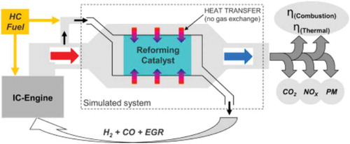
A similar test was performed by Fennell et al. (Fennell, Herreros, and Tsolakis Citation2014) modifying a conventional EGR system to a reformed exhaust gas recirculation (REGR) to improve the performance of a gasoline DI system. In the REGR design, hydrogen and CO were supplied into the EGR system as shown in . The results indicated that the REGR improved the engine efficiency in comparison to the gasoline engine, and the REGR outperformed EGR due to the extended dilution limit. The REGR largely decreased NOx formation and had moderately increased HC emissions. Both the EGR and REGR reduced or eliminated knock, as well as reduced the particulate matter number and mass emissions.
Figure 3. Schematic of a modified hydrogen-fueled engine with reformed exhaust gas recirculation (Fennell, Herreros, and Tsolakis Citation2014).
7. Hydrogen fuel cell
7.1. Application of HFC in transportation engines
Electricity generation is continually moving away from centralized generation based on fossil fuels as the technology is becoming more complex and diverse. Hydrogen and fuel cells can be incorporated into the global energy sector, but it will be difficult due to the intricacy of the structure of the energy sector. HFCs are static energy conversion systems that generate electrical energy through an electro-chemical reaction of hydrogen and oxygen. The electrical energy will be generated by HFCs as long as hydrogen/oxygen is conducted into the system. FCs have low-efficiency ratings, around 50% at lower heating value, which is inferior to batteries; however, the volumetric energy density of an HFC is much higher than the equivalent electricity capacity of a battery (Gray et al. Citation2011). Unlike in batteries, FCs do not self-discharge the hydrogen stored, because the FC itself is not the storage device which is important for long-term storage. A unique and appealing characteristic of hydrogen fuel cells is the decoupling of energy and power ratings (Eriksson and Gray Citation2017). These are proportional in a battery, which is why battery-electric vehicles (BEVs) with a large driving range are expensive, heavy, and very powerful. HFCs are superior to BEVs in the aspect of power availability because, the FC itself dictates the power capacity while the hydrogen storage sets the duration of the energy supply, similar to an ICE. HFCs alone can be used to replace a traditional ICE in the transportation sector on this similarity. Since 2007, more than 100 automobiles of the generation HydroGen4 illustrated in were manufactured in countries like the United States and Germany (Harrop and Das Citationn.d.).
Figure 4. GM HydroGen4 vehicle (CitationHarrop and Das n.d).
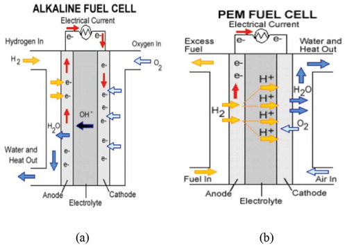
Although experiments with different types of FCs in hydrogen transportation engines have been conducted, the principal behind their function is similar. Generally, an anode, a cathode, and an electrolyte are the main components of an HFC engine where oxygen is charged to the cathode and hydrogen is supplied to the anode. Electrons are separated from hydrogen atoms at the anode and the process is accelerated by a catalyst. The electrons are conducted through a path to power an attached device and leading to the cathode, decreasing oxygen whereas the generated protons pass through a proton-conducting electrolyte. At the cathode side, the protons and oxygen are combined to form water. Generally, the HFC system employs oxygen and hydrogen to generate electricity and water with no other pollutants (Kraytsberg and Ein-Eli Citation2014).
Alkaline Fuel Cells (AFCs) or Alkaline Membrane Fuel Cells (AMFCs) and Proton Exchange Membrane Fuel Cells (PEMFCs), also known as Polymer Electrolyte Membrane Fuel Cells, are the two main types of FCs. AMFCs are similar to PEMFCs, the difference being that PEMFCs use an acid membrane instead of an alkaline membrane. AFCs can use a variety of non-precious metal catalysts at the anode and cathode, making them more affordable than PEMFCs. The challenges for AMFCs are tolerance to carbon dioxide, membrane durability and conductivity, higher temperature operation, power density, water management, and anode electrocatalysis (Alesker et al. Citation2016; Deng et al. Citation2016).
The second type of FC is PEMFC which operates at temperatures less than 120°C using perfluorosulfonic acid as the charge carrier material (Ye et al. Citation2015). They are ideal for transportation applications because they can achieve faster start-up times than other types of FCs. PEMFCs do require a significant amount of precious metals for construction, particularly platinum, which must be minimized or eliminated to improve the cell durability and manage water transport within the cell. Flooding is a common problem in PEMFCs operation which accrues due to enhancement of gas humidity which accelerates Platinum dissolution–precipitation and carbon support corrosion (Gang and Kwon Citation2016; Pei and Chen Citation2014).
A schematic of the AFC and PEMFC is shown in .
Figure 5. The operation diagram of HFC (a) Alkaline Fuel Cell (b) Proton Exchange Membrane Fuel Cell (Hames et al. Citation2018).
7.2. Technical challenges in hydrogen FCVs
During the chemical reaction within hydrogen FCs, electricity is produced with H2O and heat as byproducts. PEMFCs achieve approximately 50% efficiency and the energy that is not converted into electrical power is lost in the form of low-temperature heat (between 60°C and 80°C) (Barbir Citation2013). There are opportunities to recover the waste heat in an integrated system to raise the overall efficiency of the system. The membranes used in HFCs are sensitive to temperature, so a thermal control system should be employed to avoid causing any damage to the membrane and to optimize the performance of the FC system. Typically, the temperature of the HFC is controlled using forced convection of air or water (Lee and Skala Citation2002). Because of a thermal boundary layer, high thermal gradient was produced using this method, which decreased the performance of the HFC. To combat this issue, alternative techniques have been proposed. One technique is the using of capillary pumping systems to create higher thermal homogeneity, which improves the system performance (Oro and Bazzo Citation2015; Silva et al. Citation2012).
Vinicio et al. (Oro, de Oliveira, and Bazzo Citation2018) used the waste heat from a PEMFC to operate a chemisorption chiller, using sodium bromide impregnated in expanded graphite as the adsorbent and ammonia as refrigerant. A thermosiphon acted as the heat reservoir to decrease the temperature drop in the PEMFC stack and to integrate the thermal energy between the chemisorption system and the PEMFC. A simulation of the system was produced and validated by experimental results. The HFC power output range increased the useful energy of the hydrogen fuel, increasing the overall efficiency to 63%.
Zakaria et al. (Zakaria et al. Citation2018) used Al2O3 nanofluid as an alternative coolant for a PEMFC system and studied the thermo-electrical performance of the system. The volume concentrations of Al2O3 nanoparticles were 0.1%, 0.3%, and 0.5% in both water and a 60:40 water and Ethylene glycol mixture. The 0.5% volume concentration nanofluid in water had superior thermal conductivity compared to the base fluid, water, resulting in the cooling rate increasing by 187%. The use of nanofluids resulted in a high voltage/pressure drop. Upon analyzing the thermo-electrical ratios, it was determined that the 0.1% volume concentration of Al2O3 in water was the most advantageous nanofluid for use in a liquid-cooled PEMFC system.
Hydrogen FCs have lower power density and slower power response than batteries or ICEs so supercapacitors (SCAPs), batteries, and energy storage systems can be combined with the FC to make the system more comparable to an ICE (Ayad, Becherif, and Henni Citation2011; Ren, Ma, and Cong Citation2015; Tie and Tan Citation2013). Compared to the traditional batteries, SCAPs have a higher power density because the employed electrodes in SCAPs have lower internal resistance (Bauman and Kazerani Citation2008). Furthermore, SCAPs offer higher longevity/efficiency and their charging is done faster (Zhang et al. Citation2008). SCAPs can supply enough power to the engine system with little or no time delay, thus integrating them into an FC system is a great way to improve the power of the system. To optimize the output power management of the system, an advanced control system must be employed.
Control systems record data from the traction motor and energy storage systems, the nominal output power of the FC is compared to the vehicle power demand and the parameters are continually calculated and adjusted (Emadi et al. Citation2005). Using an energy storage device, such as a SCAP or a battery, in the FC system allows regenerative braking to be utilized. It is claimed that because automobiles are used for a limited amount of time, energy stored in the on-board hydrogen tanks of FCVs can be employed to generate power when they are parked (Alavi et al. Citation2017).
Fangzhu and Philip (Fangzhu and Cooke Citation2009) compared characteristics of an HFC car (FCX Clarity made by Honda) and an electric car (E6 model made by Chinese Company BYD) as demonstrated in .
Table 11. Comparison between an electric car and a hydrogen FCV (Fangzhu and Cooke Citation2009).
According to this table, the HFC automobile is lighter and refill time is significantly faster compared to the electric car. The energy storage in HFC car could increase to 136 kWh by improving storage technologies, which promises a considerable potential for the future of the transportation system (Wilberforce et al. Citation2017).
. summarizes well to wheel (WTW) efficiencies of an ICE vehicle, hybrid electric vehicle (HEV), BEV and HFC vehicle (Tanç et al. Citation2018). The WTW efficiency is characterized as the overall efficiency from the point where the fuel is obtained and refined into an useable product, through all of the internal components of the drivetrain, to the final power output that propels the vehicle on the road. The intermediate efficiencies vary based upon drivetrain type in the vehicle, which will be detailed further following the figure.
Figure 6. Well to wheel efficiencies of IC engine vehicle, HEV, BEV, and HFC vehicles (Tanç et al. Citation2018).
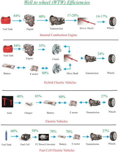
This figure illustrates the efficiency differences between the listed. For a traditional gasoline or diesel ICE, the well-to-tank efficiency, , is approximately 84%. The engine efficiency,
, of a gasoline engine is approximately 30% and 40% for a diesel engine. The tank to wheel efficiency,
, for a gasoline engine is approximately 17% and 20% for a diesel engine. The well-to-wheel efficiency for an ICE is calculated using the following equation:
The resulting well-to-wheel efficiency for gasoline and diesel ICEs is approximately 17% and 20%, respectively.
The well-to-wheel efficiency for hybrid electric vehicles, electric vehicles, and fuel cell vehicles. The figure depicts the wheel-to-well efficiency for a parallel hybrid electric vehicle, which utilizes a dual-clutch transmission that allows either the electric motor or the ICE to be coupled with the drive axel. The well-to-tank efficiency for an HEV is the same as a traditional ICE at . The efficiency of the IC engine,
, is approximately 35%. On the electric side of the system from the electric motor to the driveshaft, the powertrain-to-wheel efficiency,
, is approximately 80%. The wheel-to-well efficiency for the system with a gasoline IC engine is calculated using the following equation:
The resulting well-to-wheel efficiency of a parallel hybrid electric vehicle is approximately 24%.
For battery electric vehicles, there is no well-to-tank efficiency because the vehicle is energy storage system is a battery instead of a tank-like ICE vehicles, HEVs, and FCVs. The grid efficiency, , is the efficiency for the generation, transmission, and distribution of electricity from the average public grid. The estimated grid efficiency is 40% based on fossil-fueled power plants. The charging efficiency of the battery,
, is approximately 85%. The battery-to-wheel powertrain efficiency,
, is approximately 80% for the average BEV. The overall well-to-wheel efficiency for the BEV is calculated using the following equation:
The resulting well-to-wheel efficiency of a battery electric vehicle is approximately 27%.
Similar to the HEV, the FCV system involves an energy storage system that absorbs transient power demands on the electric motors and regenerative power from the braking system. The hydrogen used as fuel in the FCV is assumed to be produced via steam reforming of natural gas, which results in the well-to-tank efficiency of 60%. In this vehicle, the fuel cell stack acts in place of a motor or a power inverter. The efficiency of the fuel cell stack, , is approximately 58% when operating in optimum power mode and a battery is used to supplement the power output. The powertrain-to-wheel efficiency is 78%, which is slightly lower than that of HEVs due to the FC boost converter. The overall well-to-wheel efficiency of the FCV is calculated using the following equation:
The overall well-to-wheel efficiency of the hydrogen fuel cell vehicle is approximately 27%.
The FCV and BEV have the highest well-to-wheel efficiency in comparison to the ICE and HEV. There are many factors that can affect the well-to-tank efficiency of the FCV and BEV. The grid power is dependent on the type of power plant used to produce electricity; therefore, the location of the user will affect the well-to-wheel efficiency of the vehicle. Coal- and oil-fired power plants, the most common type of power plant in the United States, generally operate around 40% efficiency. On the higher end of efficient power plants, there is combined-cycle gas-fired power plants that operate from 56% to 60% efficiency, and hydropower plants that operate from 85% to 90% (Theus Citation2010). Conversely, photovoltaic solar power plants operate at the lowest efficiency of approximately 12% (Green et al. Citation2019). It is important to note that the FCV has higher well-to-wheel efficiency than the ICE despite the well-to-tank efficiency being lower for the FCV, as natural gas reforming is less efficient than refining crude oil to gasoline.
Hames et al. (Hames et al. Citation2018) analyzed four different FC control systems available and selected the ideal one based on safety, low cost, and high efficiency. The four different control systems investigated are peak power source strategy (PPSS), operating mode control strategy (OMCS), fuzzy logic control strategy (FLCS), and equivalent consumption minimization strategy (ECMS). The PPSS determines the acceleration or deceleration of the vehicle and regenerative braking energy, if regenerative braking is incorporated into the vehicle. The OMCS controls power variances and sharing between the fuel cell and battery, ensuring that enough battery power is used to meet the demand of the vehicle that is not provided by the fuel cell. The OMCS can indicate the operating mode at three different charging states: fast charge mode, charge mode, and discharge mode. The FLCS controls the power between energy storage systems to increase system efficiency and optimize the fuel economy of the vehicle. The downside of the FLCS was that it had the highest computation time due to its complexity. The ECMS controls changes in vehicle performance batteries, while the system utilizes SCAPs in addition to an FC. The battery is charged by the FC and the energy exchange is controlled by the ECM system. From comparing the four control strategies, they all have similar results. The preferred strategy is ECMS because the hydrogen consumed by the FC and battery/SCAP equivalent hydrogen consumption were minimized, it has the simplest parameters, and can be used in many vehicles while keeping the performance high. The PPSS, OMCS, and ECMS can be easily applied to different FCVs with only minor modifications due to the simplicity of the systems.
Piela et al. (Piela and Mitzel Citation2015) suggested a new definition of FC efficiency at stack level for PEMFCs. Stack losses are the stack polarization loss and reaction losses from the fuel cell itself. The reaction losses include entropy and enthalpy losses due to the fuel oxidation reaction occurring incompletely. There are some losses from the fuel not being completely used to produce useful energy due to leaks or fuel crossover through the stack membranes. The stack energy conversion efficiency, which includes electrical performance of the FC stack and considers the theoretical energy expenditures for altering the conditions of the stack feed streams and the fuel loss in the stack, was defined as:
Where is the useful power of the stack,
is the minimum theoretical power expense for stack feed streams conditioning,
is the measured electric power output of stack,
is the calculated heat power output of stack,
is the Faradaic efficiency of the fuel cell reaction, and
is the fuel efficiency of the stack. The Faradaic efficiency of the reaction and the fuel efficiency were, respectively, defined as:
Where is the effective HHV enthalpy change of the fuel cell reaction at stack inlet conditions and
is the HHV enthalpy change of ideal fuel cell reaction at stack inlet conditions. The measured electric power output of the stack and the calculated heat power output of the stack were, respectively, defined as:
Where the thermal stack voltage and
is the measured stack current. The thermal stack voltage is defined as:
Where is the number of electrons exchanged in fuel cell reaction,
is Faraday’s constant, and
is the number of cells per stack.
The Balance-of-Plant (BoP) causes energy losses from the conditions of the input and output of the stack, namely the pressure, pumping, humidification, etc. Fuel loss can also occur at the BoP when there is an excess of fuel inputted into the stack, thus a leak in the BoP occurs. Considering all of the stated losses, the BoP efficiency is defined as:
where is the fuel cell system net useful power and
is the fuel efficiency of fuel cell system BoP, which is defined as:
Where and
are the molar rate of fuel consumed by fuel cell stack and the molar rate of fuel consumed by the fuel cell system, respectively.
The system efficiency is defined as:
The equation for energy conversion efficiency at the stack level was experimentally verified using a hydrogen-fueled, liquid-cooled PEMFC stack that had 10 cells of 96 cm2 geometrical working area and a nominal electric power of 480 W each. Grade 5.0 hydrogen and 5.2 grade nitrogen were used with deionized water and ambient air. The tests involved stack startup and shutdown, testing at constant load, and polarization-curve test which followed the procedures outlined in the European Stack-Test project (Ju et al. Citation2015). The approach to designing an effective FC power system includes the selection of a stack for the system, selection of the components, making schematics for the operating scenario, and optimization of the operating conditions of the stack to obtain the highest combined system efficiency. Through the tests, it was determined that the equations developed in this experiment provide an accurate way of calculating the efficiency and optimizing the stack operating parameters of stationary hydrogen-fueled combined heat and power (CHP) system, hydrogen-fueled power-only mobile systems, and direct methanol fuel cell (DMFC) systems. The results obtained from the stack polarization tests showed that the calculated quantities were accurate in the test bench environment.
7.3. Economic challenges of hydrogen FCVs
The market entry of FCVs is dependent on early adopters purchasing or leasing the vehicles. The early adopters are people generally characterized by having a high household income, high level of education, being in larger household units, being willing to accept lifestyle changes, and other similar attributes (Rogers Citation2003). As of June 2018, there have been more than 6500 FCVs delivered to consumers. California is the leading market for FCVs with nearly 3000 vehicles being delivered due to its largest network of hydrogen refueling stations (Hardman and Tal Citation2018). In Europe, it is projected to have 600 HFC vehicles added to the current taxi fleet by the end of 2020. Zero Emission Fleet vehicles for European Roll-out (ZEFER) project, will add a total of 180 HFC vehicles, in 60 vehicle fleets, of to London, Paris and Brussels, for use in urban fleets such as police cars, private-hire vehicles and taxis (“Hype hydrogen fuel cell taxi fleet in Paris reaches 100 vehicles Citation2018). South Korea plans to expand the number of HFCVs from 100 in 2016 to 10,000 in 2020 (Yoo, Kim, and Song Citation2018). According to the International Energy Agency (IEA) Technology Roadmap, about 150 million FCVs seals is expected by 2050 (Ambrose et al. Citation2017).
Presently, several automakers are manufacturing various HFCVs, which are often compared to BEVs. Both FCVs and BEVs offer zero tailpipe emissions, the ability to be fueled using renewable energy sources, and use electric motors. The most notable differences between FCVs and BEVs are the driving range and refueling style. FCVs have above a 300-mile driving range and can be refueled in less than 10 min at a hydrogen refueling station, which is more comparable to a traditional ICE fossil fuel-powered vehicle, whereas BEVs require up to several hours to recharge completely (Lipman, Elke, and Lidicker Citation2018). The most recent FCV can be refueled in 4–5 min and have driving ranges of approximately 450–580 km (Oak Ridge National Laboratory Citationn.d).
The four FCVs currently on the market in North America, Europe, and Asia are the Hyundai Tuscon/ix35 FCEV, Nexo (“Hyundai Nexo – Sign Up For Updates | HyundaiUSA.com,” n.d.), Toyota Mirai FCEV (with a range of approximately 650 km, a maximum speed of 175 km/h, and full tank refueling in less than 3 min) (“2018 Toyota Mirai Hydrogen Fuel Cell Vehicle | The Future of Everyday [WWW Document] Citationn.d), Honda Clarity FCEV (“2018 Honda Clarity Fuel Cell – Hydrogen Powered Car | Honda [WWW Document] Citationn.d) and Daimler manufacturing the Mercedes-Benz GLC F-CELL (“The new Mercedes-Benz GLC F-CELL.,” n.d.). All four of these vehicles utilize proton exchange membrane fuel cells (PEMFCs) and use composite compressed hydrogen tanks. Increasing the performance and efficiency of FCVs is being heavily researched currently.
The numerous aforementioned government plans to implement FCV fleets in the form of public transportation will allow the hydrogen refueling station networks to maintain steady usage and help improve the public’s perception of hydrogen FCVs.
Colmenar-Santos et al. (Campíñez-Romero et al. Citation2018) designed a strategy to overcome the dilemma of implementing FCVs or creating hydrogen refueling infrastructure first by using a fleet of taxis as a stable market for hydrogen consumption. There are three objectives of the design: ensuring a consistent hydrogen supply, having alternative refueling stations throughout the city, and achieving a maximum utilization rate of the infrastructure. The city used for this model was Madrid, Spain with 15,000 HFC taxis. A base case business plan that is technically viable and financially feasible for the construction and operation of the hydrogen refueling station (HRS) network capable of supplying the hydrogen demand for the fuel cell electric taxi (FCET) fleet. The case is a simulation of the first year of operation where utilization is at its lowest and the construction and operation costs are at their highest. Internal Rate of Return (IRR) and Annual Debt Service Coverage Rate (ADSCR) methods were used to quantify the feasibility and financially viability of HRS. The Net Present Value (NPV) of the investment was evaluated from yearly income, accounting for costs assumed by the investor with 0% interest rate. From the study, it was determined that the development of an HRS network is only feasible if government support is received in the form of politics and subsidies that promote and fund the hydrogen retail infrastructure. The allocation of funds would need to aid in the construction of the HRSs, operation costs, and give tax exemptions. The optimal solution would be a subsidy package with 50% of Capex executed at the beginning of the investment, 50% of operating costs and 50% of tax exemption over 25 years. This ensures around 10% of shareholder IRR in the first 25 years, which is reasonably feasible. The estimated cost of implementing the HRS in Madrid is $415 million over 25 years, which an attainable amount in a large city. The substitution of the whole taxi fleet by FCETs in a large city would cut down CO2 emissions by around 300 kilotons per year (kt/year), which is about 3% of GHG emissions from transportation in the city.
8. Future aspects of hydrogen utilization in transportation system
The future hydrogen market depends upon potential long-term restrictions on GHGs, the cost of hydrogen and the advancement rates of different technologies that employ hydrogen (Forsberg Citation2005). The hydrogen required for FCVs must be of high purity to improve the performance and life of the stack which increases the cost of the fuel. An efficient and economical method for monitoring hydrogen purity must be integrated into the refueling network and production facilities. The motor companies must be able to achieve an acceptable return on investment when implementing the hydrogen FCV to the market. The vehicles must be sold at a reasonable profit after the engineering and manufacturing costs are recovered (Frenette and Forthoffer Citation2009).
Many social, environmental and economic benefits of hydrogen made it a promising clean energy career for future transportation system (Andrews and Shabani Citation2014). Currently, there are three important barriers that should be solved to technically/economically move forward toward a hydrogen-based transportation system. First, the cost of hydrogen production and its delivery should be considerably mitigated to introduce it on par with other fuels, such as gasoline. Hydrogen cost depends on the process applied for its production, the primary energy source, and the model adopted (centralized or decentralized methods) (Lemus and Martínez Duart Citation2010). In centralized models, hydrogen cost is influenced by the method of delivery from the production factories to the refueling stations (cryogenic liquid or compressed gas trucks, compressed gas pipelines, etc.) (Brey, Carazo, and Brey Citation2018). Second, a new or improved method of hydrogen storage for transportation vehicles should be found to ensure reasonable driving ranges. Finally, the cost of hydrogen-based vehicles (H2ICE or FCVs) should be reduced with respect to improvement in their lifetime. The future scenario of using hydrogen in the transportation system significantly depends upon the cost of hydrogen compared to the other fuels, as well as technological development in vehicles’ engine design toward hydrogen-based engines (Müller and Arlt Citation2013). Moreover, social-cultural factors play a crucial role on the development of hydrogen in the transportation system as issues related to mobility and household equipment of current conventional fossil fuel-based engines are regulated. It has been found that information campaigns have a significant influence on the development of hydrogen technologies especially at this early stage, to enhance awareness for those with low or no knowledge and to positively impact attitudes toward hydrogen vehicles (Bögel et al. Citation2018).
H2ICEs are not being researched as heavily as hydrogen fuel cells for cars and light-duty vehicles (LDV). Using hydrogen in IC engines achieves only 20–25% efficiency in comparison to FCs that achieve 60% or higher. A much larger fuel storage tank is required to supply a competitive driving range for vehicles due to lower efficiency of IC engines. The use of hydrogen in IC engines on heavy-duty vehicles (HDV) is more appealing. The existing diesel engines can be easily modified to support hydrogen fuel, making the adoption of hydrogen both easier and more affordable than adopting fuel cells. Medium- and heavy-duty (MHD) vehicles (including about one million buses and eleven million trucks) consume approximately 20–25% of energy in the US transportation sector (“National Transportation Statistics [WWW Document] Citation2017). In the U.S. transportation sector, after light-duty vehicles (pickup trucks, sports-utility vehicles, and passenger cars), MHD vehicles are the largest energy consumers and GHGs emitters (Davis, Williams, and Boundy Citationn.d; EPA (U.S. Environmental Protection Agency) Citationn.d.). Due to fast growing demand for MHD vehicles in the US transportation market, H2ICEs could be deployed in HDV for clean and sustainable transportation. In the UK, the strategy of using H2ICEs in MHD vehicles has been seriously considered; however, since they cannot achieve a competitive driving range to conventional IC engines, the strategy has not been adopted. Some companies, like ULEMCo in the UK, works to retrofit semitrucks from diesel to a dual-fuel hydrogen-diesel engine, which is slowly shifting HDV market toward a hydrogen-based future (“ULEMCo to Demonstrate First Zero Emission Combustion Engine Truck,” Citationn.d.).
There have been numerous studies that showed ways to improve the performance and efficiency of HFCs, and these methods can be applied to vehicles fuel cell stacks. Nevertheless, a lack of a harmonized standards and codes to ensure the insurability and safety of HFC technology in the transportation system is observed (US Department of Energy Citation2017a). Without a doubt, transition to hydrogen transportation engines would lead to an augmentation in gross domestic product (GDP), investment and employment opportunities (Köhler et al. Citation2010).
9. Conclusion
This study reviewed the development and challenges toward creating a clean transportation system using hydrogen-powered vehicles. As the major fuel of future, applications of hydrogen in various types of transportation engines, namely fuel cells, and IC engines were considered. Compared to fossil fuel-based ICEs, using H2 ICEs obtains 20–25% efficiency. Due to several technical barriers in H2ICEs, using hydrogen as an additive to hydrocarbon fuels has been developed as a transient solution for GHG reduction in transportation engines. Strong adaptability to rapid load changes, high energy conversion efficiency, appropriate dynamic features, low operating noise, and zero tailpipe emissions have been found as the most important characteristics of FCVs. These characteristics have made FCVs comparable to H2ICEs in terms of storage time and range, acceleration, and speed. FC engines can achieve efficiencies of up to 60%, while the rest is lost as heat. The main challenge preventing the use of hydrogen in vehicles is the on-board storage and inaccessibility to refueling stations. Significant progress must be made to provide an adequate solution to the storage issue. Both infrastructure and financial resources must be allocated to develop the hydrogen economy, which will require major political support.
Nomenclature
| = | Stoichiometric air-fuel ratios of hydrogen (kg/kg) | |
| = | Stoichiometric air-fuel ratios of gasoline (kg/kg) | |
| = | Specific heat at constant volume (J/kg.K) | |
| = | Faraday’s constant (C mol−1) | |
| = | Measured stack current (A) | |
| = | Mass of inlet air (kg) | |
| = | Mass flowrate of hydrogen (kg/s) | |
| = | Mass flowrate of gasoline (kg/s) | |
| n | = | Polytropic index |
| = | Number of cells in stack | |
| = | Stack useful power (W) | |
| = | Fuel cell system net useful power (W) | |
| = | Minimum (theoretical) power expense for stack feed streams conditioning (W) | |
| = | Measured electric power output of stack (W) | |
| = | Calculated heat power output of stack (W) | |
| Q | = | Supplied thermal energy (W) |
| T | = | Temperature (K) |
| = | Temperature at position 1 ( | |
| = | Stack voltage measured at stack electrical terminals (V) | |
| = | Thermal stack voltage (V) | |
| = | Air volume flow rate (dm3/s) of at normal condition | |
| = | Number of electrons exchanged in fuel cell reaction | |
| = | Densities of air (kg/dm3) at normal condition | |
| = | Densities of hydrogen (kg/dm3) at normal condition | |
| ε | = | Compression ratio |
| λ | = | Hydrogen equivalence ratio |
| = | Equivalence ratio | |
| = | Thermal efficiency (%) | |
| γ | = | Specific heat ratio |
| = | HHV enthalpy change of ideal fuel cell reaction at stack inlet conditions; (J.mol−1) | |
| = | Effective HHV enthalpy change of fuel cell reaction at stack inlet conditions (J.mol−1) | |
| = | Molar rate of fuel consumed by fuel cell stack (mol.s−1) | |
| = | Faradaic efficiency of fuel cell reaction (%) | |
| = | Fuel efficiency of stack (%) | |
| = | Fuel efficiency of fuel cell system BoP (%) | |
| = | Molar rate of fuel consumed by fuel cell system (mol.s−1) | |
| = | Energy conversion efficiency of fuel cell system BoP (%) | |
| = | Energy conversion efficiency at stack level (%) |
Abbreviations
| ADSCR | = | Annual Debt Service Coverage Rate |
| AFC | = | Alkaline Fuel Cell |
| AMFC | = | Alkaline Membrane Fuel Cell |
| bmep | = | Brake mean effective pressure |
| BEV | = | Battery electric vehicle |
| BoP | = | Balance-of-Plant |
| BTDC | = | Before top dead center |
| BTE | = | Brake thermal efficiency |
| CO | = | Carbon monoxide |
| CH2 | = | Compressed hydrogen |
| CI | = | Compression ignition |
| COV | = | Coefficient of variation |
| COVimep | = | Covariance of indicated mean effective pressure |
| cr | = | Compression ratio |
| DI | = | Direct injection |
| DOE | = | Department of Energy |
| ECMS | = | Equivalent consumption minimization strategy |
| ECU | = | Electronic control unit |
| EGR | = | Exhaust gas recirculation |
| EVC | = | Exhaust valve closing |
| FCV | = | Fuel cell vehicle |
| FCET | = | Fuel cell electric taxi |
| FCTO | = | Fuel Cell Technologies Office |
| FLCS | = | Fuzzy logic control strategy |
| GDI | = | Gasoline direct injection |
| GDP | = | Gross domestic product |
| GHG | = | Greenhouse gas |
| H2ICE | = | Hydrogen fueled internal combustion engine |
| HCCI | = | Homogeneous charge compression ignition |
| HECU | = | Hydrogen electric control unit |
| HEV | = | Hybrid electric vehicle |
| HFC | = | Hydrogen fuel cell |
| HRS | = | Hydrogen refueling station |
| ICE | = | Internal combustion engines |
| IEA | = | International Energy Agency |
| IRR | = | Internal Rate of Return |
| IVO | = | Intake valve opening |
| LDV | = | Light-duty vehicles |
| LHV | = | Lower heating value |
| LH2 | = | Liquid hydrogen |
| MCV | = | Minimum cycle-by-cycle variations |
| MCVVT | = | Mechanical Continuous Variable Valve Timing |
| MHD | = | Medium- and heavy-duty |
| NG | = | Natural gas |
| NOx | = | Nitric oxide |
| NPV | = | Net Present Value |
| NTSEL | = | National Traffic Safety & Environment Laboratory |
| OMCS | = | Operating mode control strategy |
| PFI | = | Port fuel injection |
| PEMFC | = | Polymer electrolyte membrane fuel cells |
| PFIHICE | = | Port fuel injection hydrogen internal combustion engine |
| PM | = | Particulate matter |
| PPSS | = | Peak power source strategy |
| REGR | = | Reformed exhaust gas recirculation |
| SCAP | = | Supercapacitors |
| SI | = | Spark ignition |
| UHC | = | Unburned hydrocarbons |
| WTW | = | Well-to-wheel |
| ZEFER | = | Zero Emission Fleet vehicles for European Roll-out |
References
- 2018 Honda Clarity Fuel Cell – Hydrogen Powered Car | Honda [WWW Document]. n.d. Accessed December 3, 2018. https://automobiles.honda.com/clarity-fuel-cell.
- 2018 Toyota Mirai Hydrogen Fuel Cell Vehicle | The Future of Everyday [WWW Document]. n.d. Accessed December 3, 2018. https://ssl.toyota.com/mirai/fcv.html
- Aasadnia, M., and M. Mehrpooya. 2018. Large-scale liquid hydrogen production methods and approaches: A review. Applied Energy 212:57–83. doi:10.1016/J.APENERGY.2017.12.033.
- Acar, C., and I. Dincer. 2018. The potential role of hydrogen as a sustainable transportation fuel to combat global warming. International Journal of Hydrogen Energy. doi:10.1016/J.IJHYDENE.2018.10.149.
- Aceves, S. M., G. D. Berry, A. H. Weisberg, F. Espinosa-Loza, and S. A. Perfect, 2006. Advanced concepts for vehicular containment of compressed and cryogenic hydrogen. 16th World Hydrog. Energy ConfWHEC, Lyon, France. 3, 94550. doi:10.1103/PhysRevLett.98.010504
- Ahluwalia, R. K., T. Q. Hua, and J. K. Peng. 2012. On-board and Off-board performance of hydrogen storage options for light-duty vehicles. International Journal of Hydrogen Energy 37:2891–910. doi:10.1016/J.IJHYDENE.2011.05.040.
- Alavi, F., E. Park Lee, N. van de Wouw, B. De Schutter, and Z. Lukszo. 2017. Fuel cell cars in a microgrid for synergies between hydrogen and electricity networks. Applied Energy 192:296–304. doi:10.1016/J.APENERGY.2016.10.084.
- Alazemi, J., and J. Andrews. 2015. Automotive hydrogen fuelling stations: An international review. Renewable and Sustainable Energy Reviews 48:483–99. doi:10.1016/J.RSER.2015.03.085.
- Alesker, M., M. Page, M. Shviro, Y. Paska, G. Gershinsky, D. R. Dekel, and D. Zitoun. 2016. Palladium/nickel bifunctional electrocatalyst for hydrogen oxidation reaction in alkaline membrane fuel cell. Journal of Power Sources 304:332–39. doi:10.1016/J.JPOWSOUR.2015.11.026.
- Álvarez Fernández, R., S. Corbera Caraballo, F. Beltrán Cilleruelo, and J. A. Lozano. 2018. Fuel optimization strategy for hydrogen fuel cell range extender vehicles applying genetic algorithms. Renewable and Sustainable Energy Reviews 81:655–68. doi:10.1016/J.RSER.2017.08.047.
- Ambrose, A. F., A. Q. Al-Amin, R. Rasiah, R. Saidur, and N. Amin. 2017. Prospects for introducing hydrogen fuel cell vehicles in Malaysia. International Journal of Hydrogen Energy 42:9125–34. doi:10.1016/J.IJHYDENE.2016.05.122.
- Amrouche, F., P. A. Erickson, J. W. Park, and S. Varnhagen. 2016. Extending the lean operation limit of a gasoline Wankel rotary engine using hydrogen enrichment. International Journal of Hydrogen Energy 41:14261–71. doi:10.1016/J.IJHYDENE.2016.06.250.
- Andrews, J., and B. Shabani. 2014. The role of hydrogen in a global sustainable energy strategy. Wiley Interdisciplinary Reviews: Energy and Environment 3:474–89. doi:10.1002/wene.103.
- Arat, H. T. 2018. Simulation of diesel hybrid electric vehicle containing hydrogen enriched CI engine. International Journal Hydrogen Energy. doi:10.1016/J.IJHYDENE.2018.10.004.
- Atkinson, K., S. Roth, M. Hirscher, and W. Grünwald. 2001. Carbon nanostructures: An efficient hydrogen storage medium for fuel cells. Fuel Cells Bulletin 4:9–12. doi:10.1016/S1464-2859(01)80733-1.
- Ayad, M. Y., M. Becherif, and A. Henni. 2011. Vehicle hybridization with fuel cell, supercapacitors and batteries by sliding mode control. Renewable Energy 36:2627–34. doi:10.1016/J.RENENE.2010.06.012.
- Bai-gang, S., T. Hua-yu, and L. Fu-shui. 2014. The distinctive characteristics of combustion duration in hydrogen internal combustion engine. International Journal of Hydrogen Energy 39:14472–78. doi:10.1016/J.IJHYDENE.2014.04.013.
- Balat, M. 2008. Potential importance of hydrogen as a future solution to environmental and transportation problems. International Journal of Hydrogen Energy 33:4013–29. doi:10.1016/J.IJHYDENE.2008.05.047.
- Balat, M., and M. Balat. 2009. Political, economic and environmental impacts of biomass-based hydrogen. International Journal of Hydrogen Energy 34:3589–603. doi:10.1016/j.ijhydene.2009.02.067.
- Ball, M., and M. Weeda. 2015. The hydrogen economy – Vision or reality? International Journal of Hydrogen Energy 40:7903–19. doi:10.1016/J.IJHYDENE.2015.04.032.
- Ball, M., and M. Wietschel. 2009. The future of hydrogen – Opportunities and challenges☆. International Journal of Hydrogen Energy 34:615–27. doi:10.1016/j.ijhydene.2008.11.014.
- Barbir, F. 2009. Transition to renewable energy systems with hydrogen as an energy carrier. Energy 34:308–12. doi:10.1016/J.ENERGY.2008.07.007.
- Barbir, F. 2013. PEM fuel cells : Theory and practice. San Diego, CA: Academic Press.
- Bauman, J., and M. Kazerani. 2008. A comparative study of fuel-cell–battery, fuel-cell–Ultracapacitor, and fuel-cell–battery–Ultracapacitor vehicles. IEEE Transactions on Vehicular Technology 57:760–69. doi:10.1109/TVT.2007.906379.
- Biniwale, R. B., S. Rayalu, S. Devotta, and M. Ichikawa. 2008. Chemical hydrides: A solution to high capacity hydrogen storage and supply. International Journal of Hydrogen Energy 33:360–65. doi:10.1016/J.IJHYDENE.2007.07.028.
- Bögel, P., C. Oltra, R. Sala, M. Lores, P. Upham, E. Dütschke, U. Schneider, and P. Wiemann. 2018. The role of attitudes in technology acceptance management: Reflections on the case of hydrogen fuel cells in Europe. Journal of Cleaner Production 188:125–35. doi:10.1016/J.JCLEPRO.2018.03.266.
- Boretti, A. 2011. Advantages of the direct injection of both diesel and hydrogen in dual fuel H2ICE. International Journal of Hydrogen Energy 36:9312–17. doi:10.1016/j.ijhydene.2011.05.037.
- Bradley, D., M. Lawes, K. Liu, S. Verhelst, and R. Woolley. 2007. Laminar burning velocities of lean hydrogen–Air mixtures at pressures up to 1.0 MPa. Combustion and Flame 149:162–72. doi:10.1016/J.COMBUSTFLAME.2006.12.002.
- Brey, J. J., A. F. Carazo, and R. Brey. 2018. Exploring the marketability of fuel cell electric vehicles in terms of infrastructure and hydrogen costs in Spain. Renewable and Sustainable Energy Reviews 82:2893–99. doi:10.1016/J.RSER.2017.10.042.
- Burhan, M., S. J. Oh, K. J. E. Chua, and K. C. Ng. 2017. Solar to hydrogen: Compact and cost effective CPV field for rooftop operation and hydrogen production. Applied Energy 194:255–66. doi:10.1016/J.APENERGY.2016.11.062.
- Cadwallader, L. C., and J. S. Herring. 1999. Safety Issues with Hydrogen as a Vehicle Fuel. Contract. US: Department of Energy.
- Campíñez-Romero, S., A. Colmenar-Santos, C. Pérez-Molina, and F. Mur-Pérez. 2018. A hydrogen refuelling stations infrastructure deployment for cities supported on fuel cell taxi roll-out. Energy 148:1018–31. doi:10.1016/J.ENERGY.2018.02.009.
- Chang, W.-C., A. Y.-J. Huang, D.-R. Huang, and T.-Y. Chen. 2016. An economic evaluation on the purification and storage of waste hydrogen for the use of fuel cell scooters. International Journal of Green Energy 13:1608–14. doi:10.1080/15435075.2016.1212199.
- Chang, X., T. Ma, and R. Wu. 2018. Impact of urban development on residents’ public transportation travel energy consumption in China: An analysis of hydrogen fuel cell vehicles alternatives. International Journal Hydrogen Energy. doi:10.1016/J.IJHYDENE.2018.09.099.
- Chapman, L. 2007. Transport and climate change: A review. Journal of Transport Geography 15:354–67. doi:10.1016/J.JTRANGEO.2006.11.008.
- Charles, W. 2006. Hydrogen markets: Implications for hydrogen production technologies. USA: Oak Ridge National Laboratory.
- Chen, S., A. Kumar, W. C. Wong, M.-S. Chiu, and X. Wang. 2019. Hydrogen value chain and fuel cells within hybrid renewable energy systems: Advanced operation and control strategies. Applied Energy 233–234:321–37. doi:10.1016/J.APENERGY.2018.10.003.
- Dalai, S., S. Vijayalakshmi, P. Sharma, and K. Y. Choo. 2014. Magnesium and iron loaded hollow glass microspheres (HGMs) for hydrogen storage. International Journal of Hydrogen Energy 39:16451–58. doi:10.1016/J.IJHYDENE.2014.03.062.
- Das, L. M. 2016. Hydrogen-fueled internal combustion engines. Compend. Hydrogen Energy 177–217. doi:10.1016/B978-1-78242-363-8.00007-4.
- Das, V., S. Padmanaban, K. Venkitusamy, R. Selvamuthukumaran, F. Blaabjerg, and P. Siano. 2017. Recent advances and challenges of fuel cell based power system architectures and control – A review. Renewable and Sustainable Energy Reviews 73:10–18. doi:10.1016/J.RSER.2017.01.148.
- Davis, S. C., S. E. Williams, and R. G. Boundy. n.d. Transportation energy data book: Edition 36.2 - Full Document [WWW Document]. Oak Ridge Natl. Lab. Accessed December 1, 2018. https://cta.ornl.gov/data/tedbfiles/Edition36_Full_Doc.pdf.
- de Oliveira, A., E. C. Moreira Dos Santos, G. C. Botelho, O. S. Valente, and J. R. Sodré. 2013. Hydrogen electronic injection system for a diesel power generator. International Journal of Hydrogen Energy 38:7986–93. doi:10.1016/J.IJHYDENE.2013.04.118.
- Deng, H., D. Wang, X. Xie, Y. Zhou, Y. Yin, Q. Du, and K. Jiao. 2016. Modeling of hydrogen alkaline membrane fuel cell with interfacial effect and water management optimization. Renewable Energy 91:166–77. doi:10.1016/J.RENENE.2016.01.054.
- Dhyani, V., and K. A. Subramanian. 2018. Experimental investigation on effects of knocking on backfire and its control in a hydrogen fueled spark ignition engine. International Journal of Hydrogen Energy 43:7169–78. doi:10.1016/J.IJHYDENE.2018.02.125.
- Dicks, A. L., and D. A. J. Rand. 2018. Fuel cell systems explained. Chichester, UK: John Wiley & Sons, Ltd. doi:10.1002/9781118706992.
- Dimitriou, P., and T. Tsujimura. 2017. A review of hydrogen as a compression ignition engine fuel. International Journal of Hydrogen Energy 42:24470–86. doi:10.1016/J.IJHYDENE.2017.07.232.
- Ditaranto, M., H. Li, and T. Løvås. 2015. Concept of hydrogen fired gas turbine cycle with exhaust gas recirculation: Assessment of combustion and emissions performance. International Journal of Greenhouse Gas Control 37:377–83. doi:10.1016/J.IJGGC.2015.04.004.
- Dos Santos, K. G., C. T. Eckert, E. De Rossi, R. A. Bariccatti, E. P. Frigo, C. A. Lindino, and H. J. Alves. 2017. Hydrogen production in the electrolysis of water in Brazil, a review. Renewable and Sustainable Energy Reviews 68:563–71. doi:10.1016/J.RSER.2016.09.128.
- Dougherty, W., S. Kartha, C. Rajan, M. Lazarus, A. Bailie, B. Runkle, and A. Fencl. 2009. Greenhouse gas reduction benefits and costs of a large-scale transition to hydrogen in the USA. Energy Policy 37:56–67. doi:10.1016/J.ENPOL.2008.06.039.
- Du, Y., X. Yu, J. Wang, H. Wu, W. Dong, and J. Gu. 2016. Research on combustion and emission characteristics of a lean burn gasoline engine with hydrogen direct-injection. International Journal of Hydrogen Energy 41:3240–48. doi:10.1016/J.IJHYDENE.2015.12.025.
- Du, Y., X. Yu, L. Liu, R. Li, X. Zuo, and Y. Sun. 2017. Effect of addition of hydrogen and exhaust gas recirculation on characteristics of hydrogen gasoline engine. International Journal of Hydrogen Energy 42:8288–98. doi:10.1016/J.IJHYDENE.2017.02.197.
- Duan, J., F. Liu, and B. Sun. 2014. Backfire control and power enhancement of a hydrogen internal combustion engine. International Journal of Hydrogen Energy 39:4581–89. doi:10.1016/J.IJHYDENE.2013.12.175.
- Edwards, P. P., V. L. Kuznetsov, W. I. F. David, and N. P. Brandon. 2008. Hydrogen and fuel cells: Towards a sustainable energy future. Energy Policy 36:4356–62. doi:10.1016/J.ENPOL.2008.09.036.
- Ehsani, M., Y. Gao, S. Longo, and K. Ebrahimi. 2018. Modern electric, hybrid electric, and fuel cell vehicles, Third ed. New York, NY: CRC Press. doi:10.1201/9780429504884.
- EL-Kassaby, M. M., Y. A. Eldrainy, M. E. Khidr, and K. I. Khidr. 2016. Effect of hydroxy (HHO) gas addition on gasoline engine performance and emissions. Alexandria Engineering Journal 55:243–51. doi:10.1016/J.AEJ.2015.10.016.
- Elnashaie, S., Z. Chen, and P. Prasad. 2007. Efficient Production and Economics of Clean-Fuel Hydrogen∗. International Journal of Green Energy 4:249–82. doi:10.1080/15435070701193100.
- Emadi, A., K. Rajashekara, S. S. Williamson, and S. M. Lukic. 2005. Topological overview of hybrid electric and fuel cell vehicular power system architectures and configurations. IEEE Transactions on Vehicular Technology 54:763–70. doi:10.1109/TVT.2005.847445.
- EPA (U.S. Environmental Protection Agency). n.d. Inventory of U.S. Greenhouse Gas Emissions and Sinks:1990–2014 [WWW Document]. Accessed December 1, 2018. https://www.epa.gov/ghgemissions/inventory-us-greenhouse-gas-emissions-and-sinks
- Eriksson, E. L. V., and E. M. Gray. 2017. Optimization and integration of hybrid renewable energy hydrogen fuel cell energy systems – A critical review. Applied Energy 202:348–64. doi:10.1016/J.APENERGY.2017.03.132.
- Ezzat, M., and I. Dincer. 2018. Development and assessment of a new hybrid vehicle with ammonia and hydrogen. Applied Energy 219:226–39. doi:10.1016/J.APENERGY.2018.03.012.
- Faizal, M., and R. Saidur. 2017. Comparative thermodynamics analysis of gasoline and hydrogen fuelled internal combustion engines. International Journal of Advanced Science Research and Management 2 (3).
- Fakioğlu, E., Y. Yürüm, and T. Nejat Veziroğlu. 2004. A review of hydrogen storage systems based on boron and its compounds. International Journal of Hydrogen Energy 29:1371–76. doi:10.1016/J.IJHYDENE.2003.12.010.
- Fangzhu, Z., and P. Cooke. 2009. The green vehicle trend: Electric, plug-in or hybrid or hydrogen fuel cell? [WWW document]. http://www.dime-eu.org/working-papers/sal3-green.
- Fayaz, H., R. Saidur, N. Razali, F. S. Anuar, A. R. Saleman, and M. R. Islam. 2012. An overview of hydrogen as a vehicle fuel. International Journal of Hydrogen Energy 16:5511–28. doi:10.1016/J.RSER.2012.06.012.
- Fennell, D., J. Herreros, and A. Tsolakis. 2014. Improving gasoline direct injection (GDI) engine efficiency and emissions with hydrogen from exhaust gas fuel reforming. International Journal of Hydrogen Energy 39:5153–62. doi:10.1016/J.IJHYDENE.2014.01.065.
- Ferguson, C. R., and A. Kirkpatrick. n.d. Internal combustion engines : Applied thermosciences. UK: Wiley.
- Fieseler, H., and L. Allidiers, 2006. Liquid hydrogen technologies for mobile use. 16th World Hydrog. Energy Conf, Lyon, France, 1–9.
- Forsberg, C. W. 2005. Hydrogen markets : Implications for hydrogen production technologies. International Journal Hydrogen 1–13. https://www.edenguard.fr/Docs%20NRJ%20Et%20Cie/Meyer%20et%20Co/122902.pdf
- Frenette, G., and D. Forthoffer. 2009. Economic & commercial viability of hydrogen fuel cell vehicles from an automotive manufacturer perspective. International Journal of Hydrogen Energy 34:3578–88. doi:10.1016/j.ijhydene.2009.02.072.
- Ganesan, V. 2012. Internal combustion engines. New Delhi, India: McGraw Hill Education (India) Pvt Ltd.
- Gang, B. G., and S. Kwon. 2016. The proton exchange membrane fuel cell systems using methanolysis of sodium borohydride as a hydrogen source with cobalt catalysts. International Journal of Green Energy 13:1224–31. doi:10.1080/15435075.2016.1183494.
- Gomes Antunes, J. M., R. Mikalsen, and A. P. Roskilly. 2009. An experimental study of a direct injection compression ignition hydrogen engine. International Journal of Hydrogen Energy 34:6516–22. doi:10.1016/J.IJHYDENE.2009.05.142.
- Gray, E. M., C. J. Webb, J. Andrews, B. Shabani, P. J. Tsai, and S. L. I. Chan. 2011. Hydrogen storage for off-grid power supply. International Journal of Hydrogen Energy 36:654–63. doi:10.1016/J.IJHYDENE.2010.09.051.
- Green, M. A., Y. Hishikawa, E. D. Dunlop, D. H. Levi, J. Hohl-Ebinger, M. Yoshita, and A. W. Y. Ho-Baillie. 2019. Solar cell efficiency tables (Version 53). Progress in Photovoltaics: Research and Applications 27:3–12. doi:10.1002/pip.3102.
- Grüger, F., L. Dylewski, M. Robinius, and D. Stolten. 2018. Carsharing with fuel cell vehicles: Sizing hydrogen refueling stations based on refueling behavior. Applied Energy 228:1540–49. doi:10.1016/J.APENERGY.2018.07.014.
- Gurz, M., E. Baltacioglu, Y. Hames, and K. Kaya. 2017. The meeting of hydrogen and automotive: A review. International Journal of Hydrogen Energy 42:23334–46. doi:10.1016/J.IJHYDENE.2017.02.124.
- Gutarevych, Y., Y. Shuba, J. Matijošius, S. Karev, E. Sokolovskij, and A. Rimkus. 2018. Intensification of the combustion process in a gasoline engine by adding a hydrogen-containing gas. International Journal of Hydrogen Energy 43:16334–43. doi:10.1016/J.IJHYDENE.2018.06.124.
- Hames, Y., K. Kaya, E. Baltacioglu, and A. Turksoy. 2018. Analysis of the control strategies for fuel saving in the hydrogen fuel cell vehicles. International Journal of Hydrogen Energy 43:10810–21. doi:10.1016/J.IJHYDENE.2017.12.150.
- Hardman, S., and G. Tal. 2018. Who are the early adopters of fuel cell vehicles? Int. International Journal of Hydrogen Energy 43:17857–66. doi:10.1016/J.IJHYDENE.2018.08.006.
- Harrop, P., and R. Das, n.d. Hybrid and pure electric cars 2009–2019 [WWW document]. http://www.idtechex.com/research/reports/hybrid_and_pure_electric_cars_2009_2019_000227.asp.
- Hawkins, A. S., and N. Hughes. 2006. Technological characterisation of hydrogen storage and distribution technologies. Social Science 1–28. https://s3.amazonaws.com/academia.edu.documents/5465208/h2storagedistributiontechnologycharacterisation.pdf?response-content-disposition=inline%3B%20filename%3DTechnological_characterisation_of_hydrog.pdf&X-Amz-Algorithm=AWS4-HMAC-SHA256&X-Amz-Credential=AKIAIWOWYYGZ2Y53UL3A%2F20191105%2Fus-east-1%2Fs3%2Faws4_request&X-Amz-Date=20191105T210751Z&X-Amz-Expires=3600&X-Amz-SignedHeaders=host&X-Amz-Signature=5120930bf6e3293b6fb6a0f45e10dfd9f1fc6492c939740c1889aa701f17958b
- Herzog, A., and M. Tatsutani. 2005. A Hydrogen future? An economic and environmental assessment of hydrogen production pathways. Natural Resources Defense Council Issue Paper 23. https://www.nrdc.org/sites/default/files/hydrogen.pdf
- Hirscher, M., M. Becher, M. Haluska, U. Dettlaff-Weglikowska, A. Quintel, G. S. Duesberg, Y.-M. Choi, P. Downes, M. Hulman, S. Roth, et al. 2001. Hydrogen storage in sonicated carbon materials. Applied Physics A Materials Science & Processing 72:129–32. doi:10.1007/s003390100816.
- Holladay, J. D., J. Hu, D. L. King, and Y. Wang. 2009. An overview of hydrogen production technologies. Catalysis Today 139:244–60. doi:10.1016/J.CATTOD.2008.08.039.
- Hosseini, S. E. 2019. Development of solar energy towards solar city Utopia. Energy sources, Part A recover. Utilization and Environmental Effects 1–14. doi:10.1080/15567036.2019.1576803.
- Hosseini, S. E., A. M. Andwari, M. A. Wahid, and G. Bagheri. 2013. A review on green energy potentials in Iran. Renewable and Sustainable Energy Reviews 27:533–45. doi:10.1016/j.rser.2013.07.015.
- Hosseini, S. E., M. Abdul Wahid, M. Jamil, A. A. M. Azli, and F. M. Mohamad. 2015a. A review on biomass-based hydrogen production for renewable energy supply. International Journal of Energy Research 39:1597–615. doi:10.1002/er.
- Hosseini, S. E., and M. A. Wahid. 2012. Necessity of biodiesel utilization as a source of renewable energy in Malaysia. Renewable and Sustainable Energy Reviews 16:5732–40. doi:10.1016/j.rser.2012.05.025.
- Hosseini, S. E., and M. A. Wahid. 2014. Development of biogas combustion in combined heat and power generation. Renewable and Sustainable Energy Reviews 40:868–75. doi:10.1016/j.rser.2014.07.204.
- Hosseini, S. E., and M. A. Wahid. 2016. Hydrogen production from renewable and sustainable energy resources: Promising green energy carrier for clean development. Renewable and Sustainable Energy Reviews 57. doi:10.1016/j.rser.2015.12.112.
- Hosseini, S. E., M. A. Wahid, and A. Ganjehkaviri. 2015b. An overview of renewable hydrogen production from thermochemical process of oil palm solid waste in Malaysia. Energy Conversion and Management 94:415–29. doi:10.1016/j.enconman.2015.02.012.
- Hovland, V., A. Pesaran, R. M. Mohring, I. A. Eason, G. M. Smith, D. Tran, R. Schaller, and T. Smith. 2003. Water and heat balance in a fuel cell vehicle with a sodium borohydride hydrogen fuel processor. SAE Transactions. doi:10.4271/2003-01-2271.
- Hwang, J. J. 2013. Sustainability study of hydrogen pathways for fuel cell vehicle applications. Renewable and Sustainable Energy Reviews 19:220–29. doi:10.1016/J.RSER.2012.11.033.
- 2018. Hype hydrogen fuel cell taxi fleet in Paris reaches 100 vehicles. Fuel Cells Bull 2 2018 (8):2. doi: 10.1016/S1464-2859(18)30271-2. https://www.sciencedirect.com/science/article/pii/S1464285918302712
- Jorgensen, S. W. 2011. Hydrogen storage tanks for vehicles: Recent progress and current status. Current Opinion in Solid State and Materials Science 15:39–43. doi:10.1016/J.COSSMS.2010.09.004.
- Ju, F. C. H., G. Agreement, T. Jungmann, C. Harms, and S. Rosini. 2015. Development of PEM fuel cell stack reference test procedures for industry. http://stacktest.zsw-bw.de
- Jurczyk, M., L. Smardz, I. Okonska, E. Jankowska, M. Nowak, and K. Smardz. 2008. Nanoscale Mg-based materials for hydrogen storage. International Journal of Hydrogen Energy 33:374–80. doi:10.1016/J.IJHYDENE.2007.07.022.
- Juste, G. L., and E. M. Benavides. 2008. Feasibility analysis of hydrogen as additional fuel in aircraft propulsion. International Journal of Green Energy 5:69–86. doi:10.1080/15435070701839421.
- Kamil, M., and M. M. Rahman. 2015. Performance prediction of spark-ignition engine running on gasoline-hydrogen and methane-hydrogen blends. Applied Energy 158:556–67. doi:10.1016/J.APENERGY.2015.08.041.
- Kapdan, I. K., and F. Kargi. 2006. Bio-hydrogen production from waste materials. Enzyme and Microbial Technology 38:569–82. doi:10.1016/j.enzmictec.2005.09.015.
- Kianfard, H., S. Khalilarya, and S. Jafarmadar. 2018. Exergy and exergoeconomic evaluation of hydrogen and distilled water production via combination of PEM electrolyzer, RO desalination unit and geothermal driven dual fluid ORC. Energy Conversion and Management 177:339–49. doi:10.1016/J.ENCONMAN.2018.09.057.
- Kim, J., K. M. Chun, S. Song, H.-K. Baek, and S. W. Lee. 2017. The effects of hydrogen on the combustion, performance and emissions of a turbo gasoline direct-injection engine with exhaust gas recirculation. International Journal of Hydrogen Energy 42:25074–87. doi:10.1016/J.IJHYDENE.2017.08.097.
- Köhler, J., M. Wietschel, L. Whitmarsh, D. Keles, and W. Schade. 2010. Infrastructure investment for a transition to hydrogen automobiles. Technological Forecasting and Social Change 77:1237–48. doi:10.1016/J.TECHFORE.2010.03.010.
- Kraytsberg, A., and Y. Ein-Eli. 2014. Review of advanced materials for proton exchange membrane fuel cells. Energy and Fuels 28:7303–30. doi:10.1021/ef501977k.
- Lasn, K., and A. T. Echtermeyer. 2014. Safety approach for composite pressure vessels for road transport of hydrogen. Part 1: Acceptable probability of failure and hydrogen mass. International Journal of Hydrogen Energy 39:14132–41. doi:10.1016/J.IJHYDENE.2014.06.116.
- Lee, D.-Y., A. Elgowainy, A. Kotz, R. Vijayagopal, and J. Marcinkoski. 2018b. Life-cycle implications of hydrogen fuel cell electric vehicle technology for medium- and heavy-duty trucks. Journal of Power Sources 393:217–29. doi:10.1016/J.JPOWSOUR.2018.05.012.
- Lee, D.-Y., A. Elgowainy, and Q. Dai. 2018a. Life cycle greenhouse gas emissions of hydrogen fuel production from chlor-alkali processes in the United States. Applied Energy 217:467–79. doi:10.1016/J.APENERGY.2018.02.132.
- Lee, J., K. Lee, J. Lee, and B. Anh. 2014. High power performance with zero NOx emission in a hydrogen-fueled spark ignition engine by valve timing and lean boosting. Fuel 128:381–89. doi:10.1016/J.FUEL.2014.03.010.
- Lee, J. H., and G. W. Skala. 2002. Cooling system for a fuel cell stack. U.S. Patent No. 6,866,955. 15 Mar. 2005.
- Lemus, R. G., and J. M. Martínez Duart. 2010. Updated hydrogen production costs and parities for conventional and renewable technologies. International Journal of Hydrogen Energy 35:3929–36. doi:10.1016/J.IJHYDENE.2010.02.034.
- Lindorfer, J., G. Reiter, R. Tichler, and H. Steinmüller. 2019. Hydrogen fuel, fuel cells, and methane. Management Global Warming 419–53. doi:10.1016/B978-0-12-814104-5.00014-4.
- Lipman, T. E., M. Elke, and J. Lidicker. 2018. Hydrogen fuel cell electric vehicle performance and user-response assessment: Results of an extended driver study. International Journal of Hydrogen Energy 43:12442–54. doi:10.1016/J.IJHYDENE.2018.04.172.
- Luo, Q., and B. Sun. 2016. Inducing factors and frequency of combustion knock in hydrogen internal combustion engines. International Journal of Hydrogen Energy 41:16296–305. doi:10.1016/J.IJHYDENE.2016.05.257.
- Ma, F., Y. Wang, S. Ding, and L. Jiang. 2009. Twenty percent hydrogen-enriched natural gas transient performance research. International Journal of Hydrogen Energy 34:6523–31. doi:10.1016/J.IJHYDENE.2009.05.135.
- Maus, S., J. Hapke, C. N. Ranong, E. Wüchner, G. Friedlmeier, and D. Wenger. 2008. Filling procedure for vehicles with compressed hydrogen tanks. International Journal of Hydrogen Energy 33:4612–21. doi:10.1016/J.IJHYDENE.2008.06.052.
- Midilli, A., M. Ay, I. Dincer, and M. A. Rosen. 2005. On hydrogen and hydrogen energy strategies: I: Current status and needs. Renewable and Sustainable Energy Reviews 9:255–71. doi:10.1016/J.RSER.2004.05.003.
- Moreno, F., M. Muñoz, J. Arroyo, O. Magén, C. Monné, and I. Suelves. 2012. Efficiency and emissions in a vehicle spark ignition engine fueled with hydrogen and methane blends. International Journal of Hydrogen Energy 37:11495–503. doi:10.1016/J.IJHYDENE.2012.04.012.
- Mori, D., and K. Hirose. 2009. Recent challenges of hydrogen storage technologies for fuel cell vehicles. International Journal of Hydrogen Energy 34:4569–74. doi:10.1016/J.IJHYDENE.2008.07.115.
- Müller, K., and W. Arlt. 2013. Status and development in hydrogen transport and storage for energy applications. Energy Technology 1:501–11. doi:10.1002/ente.201300055.
- Muradov, N., and T. Vezirolu. 2005. From hydrocarbon to hydrogen?carbon to hydrogen economy. International Journal of Hydrogen Energy 30:225–37. doi:10.1016/j.ijhydene.2004.03.033.
- Muthukumar, P., M. Prakash Maiya, and S. S. Murthy. 2005. Experiments on a metal hydride-based hydrogen storage device. International Journal of Hydrogen Energy 30:1569–81. doi:10.1016/J.IJHYDENE.2004.12.007.
- Naber, J. D., and D. L. Siebers. 1998. Hydrogen combustion under diesel engine conditions. International Journal of Hydrogen Energy 23:363–71. doi:10.1016/S0360-3199(97)00083-9.
- Nagasawa, K., F. T. Davidson, A. C. Lloyd, and M. E. Webber. 2019. Impacts of renewable hydrogen production from wind energy in electricity markets on potential hydrogen demand for light-duty vehicles. Applied Energy 235:1001–16. doi:10.1016/J.APENERGY.2018.10.067.
- National Transportation Statistics [WWW Document]. 2017. DOT (U.S. Dep. Transp. Accessed November 30, 2018. https://www.bts.gov/rita.
- Navale, S. J., R. R. Kulkarni, and S. S. Thipse. 2017. An experimental study on performance, emission and combustion parameters of hydrogen fueled spark ignition engine with the timed manifold injection system. International Journal of Hydrogen Energy 42:8299–309. doi:10.1016/J.IJHYDENE.2017.01.059.
- Oak Ridge National Laboratory. n.d. Vehicle technologies market report - 2016. US Department of Energy.
- Oro, M. V., and E. Bazzo. 2015. Flat heat pipes for potential application in fuel cell cooling. Applied Thermal Engineering 90:848–57. doi:10.1016/J.APPLTHERMALENG.2015.07.055.
- Oro, M. V., R. G. de Oliveira, and E. Bazzo. 2018. An integrated solution for waste heat recovery from fuel cells applied to adsorption systems. Applied Thermal Engineering 136:747–54. doi:10.1016/J.APPLTHERMALENG.2018.01.081.
- Paggiaro, R., F. Michl, P. Bénard, and W. Polifke. 2010. Cryo-adsorptive hydrogen storage on activated carbon. II: Investigation of the thermal effects during filling at cryogenic temperatures. International Journal of Hydrogen Energy 35:648–59. doi:10.1016/J.IJHYDENE.2009.11.013.
- Paster, M. D., R. K. Ahluwalia, G. Berry, A. Elgowainy, S. Lasher, K. McKenney, and M. Gardiner. 2011. Hydrogen storage technology options for fuel cell vehicles: Well-to-wheel costs, energy efficiencies, and greenhouse gas emissions. International Journal of Hydrogen Energy 36:14534–51. doi:10.1016/J.IJHYDENE.2011.07.056.
- Pei, P., and H. Chen. 2014. Main factors affecting the lifetime of proton exchange membrane fuel cells in vehicle applications: A review. Applied Energy 125:60–75. doi:10.1016/J.APENERGY.2014.03.048.
- Peschka, W. 1998. Hydrogen: The future cryofuel in internal combustion engines. International Journal of Hydrogen Energy 23:27–43. doi:10.1016/S0360-3199(97)00015-3.
- Petkov, T., T. Veziroǧlu, and J. S. Of. n.d. An outlook of hydrogen as an automotive fuel. International Journal of Hydrogen Energy 14:449–74. doi:10.1016/0360-3199(89)90031-1.
- Physical Hydrogen Storage | Department of Energy [WWW Document]. n.d. Accessed February.2 2018. https://www.energy.gov/eere/fuelcells/physical-hydrogen-storage.
- Piela, P., and J. Mitzel. 2015. Polymer electrolyte membrane fuel cell efficiency at the stack level. Journal of Power Sources 292:95–103. doi:10.1016/J.JPOWSOUR.2015.05.043.
- Ram, B. G. 2008. Hydrogen fuel: production, transport, and storage. USA: CRC Press.
- Reitz, R. D. 2013. Directions in internal combustion engine research. Combustion and Flame 160:1–8. doi:10.1016/j.combustflame.2012.11.002.
- Ren, G., G. Ma, and N. Cong. 2015. Review of electrical energy storage system for vehicular applications. Renewable and Sustainable Energy Reviews 41:225–36. doi:10.1016/J.RSER.2014.08.003.
- Rogers, E. M. 2003. Diffusion of innovations. USA: Free Press.
- Sakintuna, B., F. Lamari-Darkrim, and M. Hirscher. 2007. Metal hydride materials for solid hydrogen storage: A review. International Journal of Hydrogen Energy 32:1121–40. doi:10.1016/J.IJHYDENE.2006.11.022.
- Salvi, B. L., and K. A. Subramanian. 2015. Sustainable development of road transportation sector using hydrogen energy system. Renewable and Sustainable Energy Reviews 51:1132–55. doi:10.1016/J.RSER.2015.07.030.
- Satyapal, S., J. Petrovic, C. Read, G. Thomas, and G. Ordaz. 2007. The U.S. Department of energy’s national hydrogen storage project: Progress towards meeting hydrogen-powered vehicle requirements. Catalysis Today 120:246–56. doi:10.1016/J.CATTOD.2006.09.022.
- Schlapbach, L., and A. Züttel. 2010. Hydrogen-storage materials for mobile applications. In Materials for sustainable energy, ed. by Dusastre, V., 265–70. UK: Co-Published with Macmillan Publishers Ltd. doi:10.1142/9789814317665_0038.
- Sharma, S., and S. K. Ghoshal. 2015. Hydrogen the future transportation fuel: From production to applications. Renewable and Sustainable Energy Reviews 43:1151–58. doi:10.1016/J.RSER.2014.11.093.
- Shi, W., X. Yu, H. Zhang, and H. Li. 2017. Effect of spark timing on combustion and emissions of a hydrogen direct injection stratified gasoline engine. International Journal of Hydrogen Energy 42:5619–26. doi:10.1016/J.IJHYDENE.2016.02.060.
- Silva, A. P., R. M. Galante, P. R. Pelizza, and E. Bazzo. 2012. A combined capillary cooling system for fuel cells. Applied Thermal Engineering 41:104–10. doi:10.1016/J.APPLTHERMALENG.2012.01.008.
- Singh, S., S. Jain, V. PS, A. K. Tiwari, M. R. Nouni, J. K. Pandey, and S. Goel. 2015. Hydrogen: A sustainable fuel for future of the transport sector. Renewable and Sustainable Energy Reviews 51:623–33. doi:10.1016/J.RSER.2015.06.040.
- Sopena, C., P. M. Diéguez, D. Sáinz, J. C. Urroz, E. Guelbenzu, and L. M. Gandía. 2010. Conversion of a commercial spark ignition engine to run on hydrogen: Performance comparison using hydrogen and gasoline. International Journal of Hydrogen Energy 35:1420–29. doi:10.1016/J.IJHYDENE.2009.11.090.
- Sorgulu, F., and I. Dincer. 2018. Cost evaluation of two potential nuclear power plants for hydrogen production. International Journal of Hydrogen Energy 43:10522–29. doi:10.1016/J.IJHYDENE.2017.10.165.
- Srinivasan, S. 2006. Fuel cells: From fundamentals to applications. In Fuel cells, 3–25. Boston, MA: Springer Science & Business Media. doi:10.1007/0-387-35402-6_1.
- Sun, B., D. Zhang, and F. Liu. 2013. Cycle variations in a hydrogen internal combustion engine. International Journal of Hydrogen Energy 38:3778–83. doi:10.1016/J.IJHYDENE.2012.12.126.
- Szwaja, S., and K. Grab-Rogalinski. 2009. Hydrogen combustion in a compression ignition diesel engine. International Journal of Hydrogen Energy 34:4413–21. doi:10.1016/J.IJHYDENE.2009.03.020.
- Tanç, B., H. T. Arat, E. Baltacıoğlu, and K. Aydın. 2018. Overview of the next quarter century vision of hydrogen fuel cell electric vehicles. International Journal Hydrogen Energy. doi:10.1016/J.IJHYDENE.2018.10.112.
- Tartakovsky, L., and M. Sheintuch. 2018. Fuel reforming in internal combustion engines. Progress in Energy and Combustion Science 67:88–114. doi:10.1016/J.PECS.2018.02.003.
- Theus, G. 2010. Generation IV nuclear reactors. Advanced Materials and Processes 168:26–29.
- Tie, S. F., and C. W. Tan. 2013. A review of energy sources and energy management system in electric vehicles. Renewable and Sustainable Energy Reviews 20:82–102. doi:10.1016/J.RSER.2012.11.077.
- Tsujimura, T., and Y. Suzuki. 2017. The utilization of hydrogen in hydrogen/diesel dual fuel engine. International Journal of Hydrogen Energy 42:14019–29. doi:10.1016/J.IJHYDENE.2017.01.152.
- ULEMCo to Demonstrate First Zero Emission Combustion Engine Truck [WWW Document]. n.d. Accessed December 1, 2018. http://ulemco.com/?p=2638.
- US Department of Energy. 2017a. Fuel cell technologies office, multi-year research, development, and demonstration plan. Energy Efficiency and Renewable Energy.
- US Department of Energy. 2017b. Target explanation document: onboard hydrogen storage for light-duty fuel cell vehicles [WWW document]. Accessed November 2, 2018. www.uscar.org.
- Vasiliev, V. V., and E. V. Morozov. 2001. Mechanics and analysis of composite materials. The Netherlands: Elsevier.
- Verhelst, S. 2014. Recent progress in the use of hydrogen as a fuel for internal combustion engines. International Journal of Hydrogen Energy 39:1071–85. doi:10.1016/J.IJHYDENE.2013.10.102.
- Verhelst, S., and R. Sierens. 2001. Hydrogen engine-specific properties. International Journal of Hydrogen Energy 26:987–90. doi:10.1016/S0360-3199(01)00026-X.
- Verhelst, S., and T. Wallner. 2009. Hydrogen-fueled internal combustion engines. Progress in Energy and Combustion Science 35:490–527. doi:10.1016/J.PECS.2009.08.001.
- Veziroğlu, T. N., and S. Şahi˙n. 2008. 21st Century’s energy: Hydrogen energy system. Energy Conversion and Management 49:1820–31. doi:10.1016/j.enconman.2007.08.015.
- Wallner, T., 2004. Development of combustion concepts for a hydrogen powered internal combustion engine. Diss. Ph. D. thesis, Graz University of Technology.
- Wang, L., Z. Yang, Y. Huang, D. Liu, J. Duan, S. Guo, and Z. Qin. 2017. The effect of hydrogen injection parameters on the quality of hydrogen–Air mixture formation for a PFI hydrogen internal combustion engine. International Journal of Hydrogen Energy 42:23832–45. doi:10.1016/J.IJHYDENE.2017.04.086.
- White, C. M., R. R. Steeper, and A. E. Lutz. 2006. The hydrogen-fueled internal combustion engine: A technical review. International Journal of Hydrogen Energy 31:1292–305. doi:10.1016/J.IJHYDENE.2005.12.001.
- Wilberforce, T., Z. El-Hassan, F. N. Khatib, A. Al Makky, A. Baroutaji, J. G. Carton, and A. G. Olabi. 2017. Developments of electric cars and fuel cell hydrogen electric cars. International Journal of Hydrogen Energy 42:25695–734. doi:10.1016/J.IJHYDENE.2017.07.054.
- Xiao, X., L. Chen, X. Wang, S. Li, C. Chen, and Q. Wang. 2008. Reversible hydrogen storage properties and favorable co-doping mechanism of the metallic Ti and Zr co-doped sodium aluminum hydride. International Journal of Hydrogen Energy 33:64–73. doi:10.1016/J.IJHYDENE.2007.09.015.
- Xu, W.-C., K. Takahashi, Y. Matsuo, Y. Hattori, M. Kumagai, S. Ishiyama, K. Kaneko, and S. Iijima. 2007. Investigation of hydrogen storage capacity of various carbon materials. International Journal of Hydrogen Energy 32:2504–12. doi:10.1016/J.IJHYDENE.2006.11.012.
- Yan, F., L. Xu, and Y. Wang. 2018. Application of hydrogen enriched natural gas in spark ignition IC engines: From fundamental fuel properties to engine performances and emissions. Renewable and Sustainable Energy Reviews 82:1457–88. doi:10.1016/J.RSER.2017.05.227.
- Yang, C., and J. Ogden. 2007. Determining the lowest-cost hydrogen delivery mode. International Journal of Hydrogen Energy 32:268–86. doi:10.1016/J.IJHYDENE.2006.05.009.
- Yang, C., M. Nicholas, and J. Ogden. 2006. Comparison of idealized and real-world city station citing models for hydrogen distribution. Davis, CA: Institute of Transportation Studies, University of California.
- Yang, Z., F. Zhang, L. Wang, K. Wang, and D. Zhang. 2018. Effects of injection mode on the mixture formation and combustion performance of the hydrogen internal combustion engine. Energy 147:715–28. doi:10.1016/J.ENERGY.2018.01.068.
- Ye, L., K. Jiao, Q. Du, and Y. Yin. 2015. Exergy analysis of high-temperature proton exchange membrane fuel cell systems. International Journal of Green Energy 12:917–29. doi:10.1080/15435075.2014.892004.
- Yoo, E., M. Kim, and H. H. Song. 2018. Well-to-wheel analysis of hydrogen fuel-cell electric vehicle in Korea. International Journal of Hydrogen Energy 43:19267–78. doi:10.1016/J.IJHYDENE.2018.08.088.
- Yu, X., H. Wu, Y. Du, Y. Tang, L. Liu, and R. Niu. 2016. Research on cycle-by-cycle variations of an SI engine with hydrogen direct injection under lean burn conditions. Applied Thermal Engineering 109:569–81. doi:10.1016/J.APPLTHERMALENG.2016.08.077.
- Zakaria, I., W. A. N. W. Mohamed, W. H. Azmi, A. M. I. Mamat, R. Mamat, and W. R. W. Daud. 2018. Thermo-electrical performance of PEM fuel cell using Al2O3 nanofluids. International Journal of Heat and Mass Transfer 119:460–71. doi:10.1016/J.IJHEATMASSTRANSFER.2017.11.137.
- Zeng, K., and D. Zhang. 2010. Recent progress in alkaline water electrolysis for hydrogen production and applications. Progress in Energy and Combustion Science 36:307–26. doi:10.1016/J.PECS.2009.11.002.
- Zhang, J., T. S. Fisher, P. V. Ramachandran, J. P. Gore, and I. Mudawar. 2005. A review of heat transfer issues in hydrogen storage technologies. Journal of Heat Transfer 127:1391. doi:10.1115/1.2098875.
- Zhang, Y., L. Wu, X. Hu, and H. Liang, 2008. Model and control for supercapacitor-based energy storage system for metro vehicles, inElectrical machines: And systems, 2008. ICEMS 2008. International Conference on. Wuhan, China: IEEE.
- Zhou, L. 2005. Progress and problems in hydrogen storage methods. Renewable and Sustainable Energy Reviews 9:395–408. doi:10.1016/J.RSER.2004.05.005.
- Züttel, A. 2004. Hydrogen storage methods. Naturwissenschaften 91:157–72. doi:10.1007/s00114-004-0516-x.