
Abstract
Advances in emerging technology of microelectromechanical systems (MEMS) are one of the most challenging tasks in today's experimental mechanics. More specifically, development of these miniature devices requires sophisticated design, analysis, fabrication, testing, and characterization tools that have multiphysics and multiscale capabilities, especially as MEMS are being developed for use at harsh conditions. In harsh-environment and high-performance (e.g., military) guidance applications inertial sensors must be sensitive to low rates of rotation yet survive the high blast loads associated with the initial launch. In this multi-year study, a set of tuning fork gyroscopes were subjected to a series of increasing g-loads (culminating at approximately 60,000 g's) with measurements of shape made after each test. A custom set of test sample packages (aka articles) were hermetically sealed with glass lids to allow optical inspection of components while preserving the operating environment (i.e., vacuum). Initial test measurements were made upon fabrication of the articles. Optical and interferometric measurements have been made prior to and after each shock g-loading. The shape of the tuning fork gyroscope (TFG) test articles was measured using a phase shifting Michelson interferometer with compensation for package cover glass. Full field shape was determined and traces of pertinent structures were extracted for comparison. Failure of the die was observed in the form of fractures below the chip surface as well as fractures in the glass lid sealing the package. Potential causes of the failure are discussed as well as a recommendation for modified packaging techniques to mitigate future component failures.
NOMENCLATURE
| CCD | = |
charge coupled device |
| I | = |
intensity |
| IMU | = |
inertial measurement unit |
| K | = |
sensitivity vector |
| K 1 | = |
illumination vector |
| K 2 | = |
observation vector |
| L | = |
displacement/deformation vector |
| MEMS | = |
microelectromechanical system |
| RH | = |
relative humidity |
| SOI | = |
silicon on insulator |
| TEMA | = |
TrackEye Motion Analysis |
| TFG | = |
Tuning Fork Gyroscope |
| VI | = |
Virtual Instrument |
| WPI | = |
Worcester Polytechnic Institute |
|
| = |
transpose of the matrix of sensitivity vectors |
| x,y | = |
spatial coordinates |
| λ | = |
illumination wavelength |
| θn | = |
nth phase step (n = 1,2 … 5) |
| Ω (x,y) | = |
fringe-locus function |
1. INTRODUCTION
Military grade MEMS gyroscopes are critical for navigation in guided munitions. In such applications the sensor must survive extremely harsh launch environments and maintain integrity, often requiring sensitivity to loads many orders of magnitude lower than those experienced during launch. Previous inertial measurement units (IMUs) have proven to remain functional at loads up to 20,000 g's.[ Citation 1 ] In other work, gyroscopes (as well as other MEMS) have proven to survive loading up to 60,000 g's.[ Citation 2 ] In these previous works, performance was examined exclusively by electrical means. The current study aims to monitor the mechanical effects that such loading will have on the die and structure through interferometric shape measurement of the sensors.
A custom set of gyroscopes was fabricated at Draper Laboratory to allow for optical measurements, Figure . A glass lid, Corning Pyrex® 7740 metalized with a seal ring, provides a hermetic seal while allowing optical inspection of the device. The MEMS structure was fabricated using Silicon on Insulator (SOI) processing and anodically bonding the structure onto a Hoya glass substrate.[ Citation 3 ] The individual die was brazed into the package with AuSn eutectic and electrical connections were made by wire bonding.
Figure 1 Tuning fork gyroscope (TFG): (a) packaged component, (b) MEMS die.
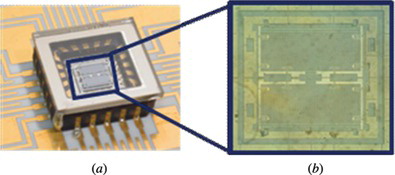
A total of four test articles were received by WPI in 2005, referred to herein as test articles g01 through g04, respectively. Quantitative measurements of shape were made in two phases. In Phase-1 initial testing monitored the shape of the component as a function of time, with static shape measurements made upon receipt and repeated in 2007 and 2009. In Phase-2 inertial loading was performed in 2009 and finalized in 2010, with comparison made after various loads. Shape results were compared for measurements of Phase-1 and Phase-2. Optical inspection was also performed to identify failures in chips and/or packages.
2. EXPERIMENTAL PROCEDURES
The shape of the tuning fork gyroscope (TFG) test articles was measured using a modular optoelectronic station, Figure , developed especially for characterization of MEMS.[ Citation 4 , Citation 5 ] In this station, the interchangeable optical subsystems were developed to have long working distance to accommodate an environmental chamber to conveniently place and hold MEMS being investigated/characterized while subjecting them to various thermomechanical loads, including vibrations, under well controlled temperature (for heating and cooling) as well as pressure/vacuum conditions. Specifically, measurements were made using a phase shifting Michelson interferometer with compensation for package cover glass using a light emitting diode (LED) operating at λ ≈ 640 nm. The shape measurements extracted were a function of the interferometer geometry as well as the illumination wavelength. Throughout the duration (about 5.5 years) of this investigation an improved microscope configuration was developed.[ Citation 5 ] To account for the use of multiple microscopes the wavelength of each LED was characterized over the full current range. The driving current was recorded for each measurement and used during analysis.
Figure 2 Schematic of a modular optoelectronic station for characterization of MEMS: (1) interchangeable interferometer module, (2) environmental chamber, (3) turbomolecular vacuum pump.
Custom user interface has been developed for the modular optoelectronic station.[ Citation 5 ] It is based on LabView software, with MatLab scripts embedded where needed. Communication with the hardware is achieved through IEEE 488 (GPIB), RS-232 (serial), and IEEE 1394 (Firewire) interfaces. The custom interface has been developed as a modular system. Nearly every piece of hardware is controlled by its own Virtual Instrument (VI). Also contained in the package are VIs which control many pieces of equipment to perform a scripted experiment, such as thermal cycling with data measurements. Finally, there are VIs whose sole function is to perform specific analysis, such as calculation of the measurement phase step. The main user interface, which is displayed upon execution of the software, acts as the control panel for launching specific sub-programs.
A LED illumination was selected to prevent the observation of fringes on multiple surfaces of a TFG. Otherwise complex masking was required for surface selection with the use of laser illumination due to the long coherence length. This process was avoided with the use of a modulation threshold filter in which only the focused surface modulates, such as with the LED illumination because of its short coherence. Due to the short coherence length a compensation glass was placed in the reference arm of the interferometer to match the path length to that of the object beam of the interferometer.
A five phase step algorithm was applied using 90 degree phase steps to analyze the surface of a gyroscope.[ Citation 6 , Citation 7 ] Images recorded by the CCD camera are processed by the system computer, serving as the image processor, to determine the fringe-locus function, Ω(x,y), constant values of which define fringe loci on the surface of an object under investigation. The values of Ω relate to the system geometry and the unknown vector L, defining displacements and deformations, via the relationship[ Citation 6 ]
Quantitative determination of structural displacements/deformations due to the applied loads can be obtained, by solving a system of equations similar to Equation 1, to yield[ Citation 6 ]
In the case of the 5-phase-steps algorithm with θn = 0, π/2, π, 3π/2, and 2π, the distribution of the values of Ω(x,y) can be determined using[ Citation 7 ]
Results produced by Equation 3 depend on capabilities of the illuminating, the imaging, and the processing subsystems of the optoelectronic system used in the specific application. Developments in laser, fiber optic, CCD camera, and computer technologies have led to advances in the optoelectronic methodology.
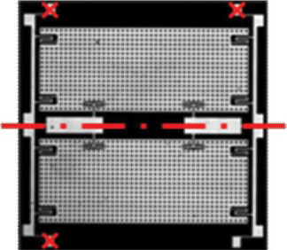
In the current study, rigid body motion was compensated by subtraction of a plane fit through three supporting posts of the gyroscope. Line traces were then extracted from pertinent structures to clearly examine changes in the TFG. The location of the extracted traces has been selected to avoid areas that are freely suspended above the chip. The trace passes through center islands which are fixed directly to the chip substrate, providing information about the chip shape, Figure . In this figure, the three posts used to generate the plane for rigid body corrections are identified by the X marks. Full field shape was determined and traces of pertinent structures were extracted for comparison.
Figure 3 Modulation map of MEMS surface with identification of leveling points and extracted trace(s).
Initial test measurements were made upon fabrication of the devices. Shape measurements were repeated after 2 and 4 years of storage at ambient laboratory conditions (70°F, 50% RH). After four years of storage the high g-load testing was performed with additional shape measurements made before and after each stage of loading. Loads initially began at approximately 10,000 g's.
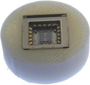
High g-loading was conducted at the University of Alabama in Huntsville's Aerophysics Research Center located on Redstone Arsenal, Alabama. This facility houses and operates three light gas gun ranges for the purpose of performing experiments and supporting analysis for the evaluation/assessment of hypersonic flight and hypervelocity impact phenomenology. High-g testing was conducted within the large impact chamber using a custom fabricated mini powder gun with a 1.2 in. bore × 3.5 in. barrel. The test article was contained within a 2 in. diameter x 1.25 in. block, Figure , located at the muzzle bonded to a 1.2 in. diameter shaft within the barrel.
Figure 4 The test article g01 assembled within a 2 in. diameter 1.25 in. long block.
The high-g loading on the article was provided by accelerating the shaft within the barrel which transferred the load to the test article at the muzzle. Varying the propellant type and weight determined the peak loading on the test article. Acceleration was determined by measuring the displacement history of the sample package using a Vision Research Phantom V7.0 (Phase-1) or a Phantom V710 (Phase-2) high speed video camera. The positions and times were recorded with the TrackEye Motion Analysis (TEMA) video software.
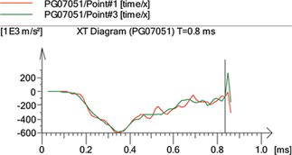
A series of images extracted from a video of a specific test were used to determine a plot of various point accelerations as a function of time Figure .
Figure 5 Acceleration as a function of time for a specific test.
The test article was contained within an aluminum test cylinder. A “soft” recovery system decelerated the aluminum fixture at a rate much slower than the initial acceleration.
A number of tests were conducted to characterize the loading conditions needed to meet the desired test requirements. The position as a function of time was recorded by the high speed camera, allowing for differentiation to determine velocity and acceleration. Initially, loading was performed at 10,000 and 20,000 g's and only two articles were subjected to the 10,000 g acceleration in the event that this loading would destroy the components. After the survival of both test articles at the 10,000 g-load all four samples were subjected to the 20,000 and 60,000 g-loads.
3. RESULTS
Four components were measured at multiple time intervals as well as after high g-loadings. For comparison purposes all test measurement results have been presented per test article.
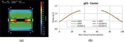
Even though articles g02 and g04 exhibited visible damage of their packages after 20,000 g-load, their functional characteristics were not compromised. Therefore all four test articles were subjected to the final test at 60,000 g-load. Three articles: g01, g02, and g04 suffered destruction of the glass lid, Figure , which led to loss of vacuum and made then not functional. As a result the only surviving article g03 was measured after the 60,000 g-load, Figure , where all 6 traces display maximum deformation of about 1.3 µm.
Figure 6 All test articles after the 60,000 g-load. Severe glass cover failure observed in three articles: g01, g02, and g04.
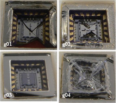
Figure 7 Surviving article g03: (a) full field of view (FFV) in 2010, (b) traces of all six shape measurements.
4. DISCUSSION
Four custom test articles with sealed glass lids have been studied as functions of time and high-g inertial loading. During initial loading up to 20,000 g, the glass lid has survived loadings and the line traces through the center islands of the test articles were nearly indistinguishable.
Sample g02 has been damaged at 20,000 g-load, yet there was no evidence of an adverse effect on the MEMS component within the package.
Sample g03 appears to have been damaged in a cosmetic manner only, by the chip in the corner of the glass lid. This defect did not appear severe enough to compromise the integrity of the hermetic seal.
Sample g04 has been severely damaged, with a crack in the glass lid as well as the Hoya glass substrate on which the MEMS has been bonded. Interferometric analysis showed a major change in the shape of the structure. In the event of a more robust metal lid to the package the shock may still be sufficient to fracture the MEMS substrate without compromising the vacuum environment of the package. It is unknown if the gyroscope would function at all, yet the response would be inaccurate if able to drive and respond to rotations.
Loading of the test articles at 60,000 g's was devastating as only one out of four articles, g03, survived. In this case all six traces were very repeatable and indicated no damage to the sensor. The remaining three articles were destroyed and were not functional because of loss of the operating environment (vacuum).
5. CONCLUSIONS
Traditionally MEMS response to high-g loading has consisted of electrical characterization after loading. Current study has presented a method using which mechanical damage may be assessed for shock loading by the gas gun up to 60,000 g's. Cover glass reliability is an issue in that a failure of the lid may be observed in this testing that may not occur with a metal lid such as those used in actual flight systems.
Testing on TFG components shows that prior to fracture failure, as observed in g03, there is little effect on the shape of the MEMS component. This suggests that any deformations during the loading are elastic and the device will remain functional after the load is removed.
The boundary condition of the gyroscope may be a critical design component. All devices in this study have a braze die attachment. Although robust due to the large area of the die bond this technique has recently been surpassed by gold bump die bonding of military grade inertial sensors into packages. The gold bump bond provides less residual stress in the device after cooling from bond temperatures to ambient.[ Citation 8 ]
ACKNOWLEDGMENTS
The author gratefully acknowledges support by various project sponsors and thanks for permission to include results of their programs in this article. Contributions by various members of CHSLT are also acknowledged and very appreciated.
Notes
Color versions of one or more of the figures in the article can be found online at www.tandfonline. com/uopt.
REFERENCES
- Karnick , D. ; Ballas , G. ; Koland , L. ; Secord , M. ; Braman , T. ; Kourepenis , T. Honeywell gun-hard inertial measurement unit (IMU) development . Position Location and Navigation Symposium, PLANS 2004 , 4 , 49 – 55 .
- Brown , T.G. Harsh military environments and microelectromechanical (MEMS) devices . Proc. IEEE Sensors 2003 , 2 , 753 – 760 .
- Marinis , T.F. ; Soucy , J.W. ; Lawrence , J.G. ; Marinis , R.T. ; Pryputniewicz , R.J. Vacuum sealed MEMS package with an optical window . IEEE Electronics Components and Technology Conference (ECTC) , Orlando , FL , 2008 ; IEEE: New York ; pp. 804 – 810 .
- Klempner , A.R. Development of a modular interferometric microscopy system for characterization of MEMS. MS Thesis, Worcester Polytechnic Institute, Worcester, MA, 2006 .
- Marinis , R.T. Development and implementation of automated interferometric microscope system for study of MEMS inertial sensors, Ph.D. Dissertation, Worcester Polytechnic Institute, Worcester, MA, 2009.
- Pryputniewicz , R.J. Quantitative determination of displacements and strains from holograms . In Holographic Interferometry , Vol. 68 of Springer Series in Sciences , P. Rastogi , Ed.; Springer-Verlag : Berlin , 1995 ; pp. 33 – 72 .
- Furlong , C. Hybrid, experimental and computational, approach for the efficient study and optimization of mechanical and electro-mechanical components, Ph.D. Dissertation, Worcester Polytechnic Institute, Worcester, MA, 1999.
- Marinis , T.F. ; Soucy , J.W. Gold bump attachment of MEM sensor die using thermocompression bonding . 53rd Electronic Components & Technology Conference (ECTC) , New Orleans , LA , 2003 ; IEEE: New York ; pp. 385 – 391 .
- Color versions of one or more of the figures in the article can be found online at www.tandfonline. com/uopt.