Abstract
Proof load tests of bridges can be very useful for structures with a lack of information, or for structures of which the effect of material degradation is difficult to assess. Contrary to diagnostic load testing, proof load testing is not well-defined in current standards in terms of required load and analysis of measurements. The risk related to the high loads used in proof load testing requires standardisation for these tests. The paper highlights important considerations for proof load testing that may lead to the development of guidelines in the Netherlands, by illustrating a pilot study on the viaduct Zijlweg in the Netherlands. This reinforced concrete bridge rates too low in shear. Topics of interest are the required load that the bridge has to withstand to be approved by the load test and the interpretation of the measurements during the test to avoid permanent damage to the structure. These measurements were compared to the stop criteria from existing codes for buildings, to examine if recommendations for the use with bridges can be formulated. The final result of the test on this case study is that the capacity of the viaduct is proven to be sufficient for shear and bending moment.
1. Introduction
In the Netherlands, a large number of existing bridges are found not to fulfil the code requirements upon assessment. In particular, the shear capacity of a large number of reinforced concrete slab bridges (Lantsoght, van der Veen, Walraven, & de Boer, Citation2013) is subjected to discussion. The reason for this discussion is twofold: these bridges are reaching the end of their originally devised service life on one hand, and on the other hand, they were designed for lower demands with regard to the live loads. Moreover, the recently introduced NEN-EN 1992-1-1:2005 (CEN, Citation2005) allows for smaller shear capacities than the previously described national codes. Low ratings of slab bridges are also reported in the United States (Davids, Poulin, & Goslin, Citation2013).
In line with the approach of Levels of Approximation as introduced in the fib Model Code 2010 (fib, Citation2012), for the assessment of the existing concrete bridges in the Netherlands (mostly reinforced concrete solid slab bridges), Levels of Assessment (Lantsoght, de Boer, & van der Veen, Citation2017) have been developed:
| (1) | Level of Assessment I: a spreadsheet-based tool, the Quick Scan (Vergoossen, Naaktgeboren, ‘t Hart, de Boer, & Van Vugt, Citation2013), that quickly identifies which cross-sections need further study. | ||||
| (2) | Level of Assessment II: determination of the governing stresses with a linear finite element programme (Lantsoght, de Boer, Van der Veen, & Walraven, Citation2013). | ||||
| (3) | Level of Assessment III: analysing the structure with a non-linear finite element analysis (Rijkswaterstaat, Citation2012), or with a probabilistic analysis (Steenbergen, de Boer, & van der Veen, Citation2011). | ||||
| (4) | Level of Assessment IV: proof loading of the structure (Koekkoek, Lantsoght, Yang, Boer, & Hordijk, Citation2016). | ||||
Two types of load testing, each with different goals, can be carried out in practice. The first type is diagnostic load testing, which has as its main goal to verify assumptions used in analytical models, for example with regard to transverse distribution or stiffness. The measured results of the diagnostic load test are then used to update the analytical model, which then, in turn, is used to provide an updated rating factor. The second type is proof load testing, which is used to experimentally show that a structure fulfils the requirements with regard to being able to sustain the prescribed loads without signs of distress. As proof load testing involves high load levels, there is a risk of damaging the structure or causing a collapse. Since shear is a brittle failure mode, proof load testing for shear is not permitted by any of the current codes. Additionally, a structure subjected to a proof load test needs to be closely monitored, and the structural response needs to be analysed in terms of stop criteria. Stop criteria are criteria based on the measured structural response, which indicate that irreversible damage can occur if loading past the point of reaching a stop criterion is carried out.
Load tests cannot answer questions with regard to the ultimate capacity of the studied structure. For this purpose, collapse tests are necessary. One example of a collapse test of an existing reinforced concrete slab bridge is the test on the Ruytenschildt Bridge (Lantsoght, Van der Veen, de Boer, & Hordijk, Citation2016). This paper discusses a pilot proof load test, and focuses on the determination of the required load to approve a bridge and on the required measurements during the test and associated stop criteria. The pilot was carried out on viaduct Zijlweg, a reinforced concrete solid slab bridge. The rating for shear for this bridge was too low, caused by an expected reduction in the shear capacity due to alkali-silica reaction damage. The ultimate limit states of bending moment and shear were studied through a proof load test. Proof load testing for shear is a new area of research, since no existing code permits proof load testing for a brittle failure mode such as shear.
Safety against failure and sufficient capacity are related to a reliability index. In the Netherlands, different safety levels are used for the assessment of existing structures, as given in the Guidelines for the Assessment of Reinforced Concrete Bridges of the Ministry of Infrastructure and the Environment (Rijkswaterstaat, Citation2013) and in the Dutch code NEN 8700:2011 (Code Committee 351001, Citation2011a). An overview of these safety levels is given in Table . The value of γsw has been modified from the value prescribed in the codes for assessment. This modification results in a lower value of γsw that can be used in combination with proof load testing. The reason why the value of γsw can be lowered is that at the moment of proof load testing, the self-weight of the bridge can be considered as a deterministic value. The only element that remains to determine the load factor is then the model factor.
Table 1. Different safety levels for assessment of existing structures and associated load factors, when used in combination with proof load testing.
2. Literature review
2.1. Proof load testing for shear in the view of the current standards and guidelines
In Germany, proof load testing is mostly used for buildings, and a guideline originally developed for concrete buildings of which the flexural capacity has to be verified exists (Deutscher Ausschuss für Stahlbeton, Citation2000). In Germany, research on proof load testing for shear has started (Schacht, Bolle, Curbach, & Marx, Citation2016). In the U.S.A, a guideline exists for diagnostic and proof load testing of bridges (NCHRP, Citation1998), and these recommendations are also adopted in the Manual for Bridge Evaluation (AASHTO, Citation2011). The target proof load is taken as the vehicle the bridge needs to be rated for, multiplied with a certain factor (usually 1.4).
This method cannot be directly translated to European practice, since no Eurocodes exist yet, adopted by all European countries, for the assessment of existing bridges, and because the design tandem used in the design code is not a direct representation of a certain vehicle type. Most attention in the NCHRP guideline is geared towards diagnostic load tests. For proof load tests, no stop criteria are defined and testing for shear is not permitted. Additionally, in the U.S.A ACI code 437.2M-13 for buildings (ACI Committee 437, Citation2013) describes proof load tests. ACI 437.2M-13 allows monotonic and cyclic loading protocols, and defines stop criteria (called acceptance criteria). The required load is determined based on a load combination for existing structures, which permits lower load factors than in the load combination for design. However, proof load testing for shear is not permitted.
2.2. Effect of alkali–silica reaction
2.2.1. Introduction to alkali–silica reaction
The viaduct Zijlweg has material damage caused by alkali–silica reaction (ASR), which led to discussions about its structural capacity. ASR is the reaction between the reactive (glasslike) silica in some aggregates and alkali from the cement paste (Neville, Citation2012). The result of this reaction is a gel of calcium silicate hydrate. Upon contact with water, this gel will expand, and this expansion causes stresses in the concrete. If these stresses exceed the tensile strength of the concrete, cracking occurs, and the structural capacity is reduced. The effect of ASR on the concrete strength is typically expressed as a reduction as a function of the amount of free expansion of the concrete (Siemes, Han, & Visser, Citation2002).
The reduction is larger for the tensile strength than for the compressive strength, since tensile strength is governed by the weakest link. In the literature, the reduction of the tensile strength due to ASR is reported to vary between 5% (Ahmed, Burley, & Rigden, Citation1999) and 82% (Siemes et al., Citation2002). For reinforced concrete structures, the expansion is limited in the direction of reinforcement bars, but not in the vertical direction when no transverse reinforcement is available. As a result, cracking occurs parallel to the reinforcement.
2.2.2. Effect of ASR on structural capacity
Since bending moment capacity is governed by crushing of the concrete (failure of concrete in compression), ASR is expected to have a small influence on the bending moment capacity, as reflected in some experiments (Giaccio, Zerbino, Ponce, & Batic, Citation2008; Talley, Citation2009). Other experiments (Haddad, Shannag, & Al-Hambouth, Citation2008) reported a reduction of the flexural capacity of beams with ASR-damage of 11% as compared to undamaged beams. However, the cracking moment and stiffness of the damaged beam increased, which can be explained by the fact that the restraint of the ASR-expansion can induce prestressing into a section. In Dutch practice, the effect of ASR-damage on the bending moment capacity is not considered for rating purposes.
In terms of the shear capacity of beams with ASR damage as compared to beams without damage, conflicting results can be found in the literature. In some cases (Ahmed, Burley, & Rigden, Citation1998), the shear capacity is found to be larger in the beam with ASR damage. This increase is attributed to the prestressing effect of ASR. In a literature survey (Schmidt, Hansen, Barbosa, & Henriksen, Citation2014), it was also reported that some experiments indicate that ASR damage reduces the shear capacity while others find an increase up to 78%. For beams sawn from ASR-affected viaducts (den Uijl & Kaptijn, Citation2002), it was found that the shear capacity of the beams was 77% of the capacity of undamaged beams. A 25% reduction of the capacity in shear was thus recommended, and this recommendation is followed in the Netherlands for the rating of structures with ASR-damage.
2.2.3. Prevalence of ASR in the Dutch road network
The number of structures (bridges, tunnels and locks) affected by alkali–silica reaction is estimated to be between 40 and 50 in the Netherlands, including a series of bridges in and over the highway A59, of which the viaduct Zijlweg is part. Deleterious ASR mainly occurs in structures made with Portland cement, and generally is much less prevalent in structures with blended cements with high slag contents. The aggregates that contain reactive silica leading to ASR are porous chert, chalcedony, and impure sandstones that often react as porous chert (Nijland & Siemes, Citation2002). Eighteen ASR-affected viaducts in the Netherlands are monitored (Borsje, Peelen, Postema, & Bakker, Citation2002), including the viaduct Zijlweg.
2.2.4. Testing of ASR-damaged viaducts
A number of viaducts with ASR-damage have been load tested in the past by diagnostic load tests and for a critical position for bending moment for all but one case. Examples of tested bridges include the Hanshin expressway in Japan, viaducts in the A26 in France, a double deck road structure in South Africa, and bridges in Denmark. For the French viaducts, which had been load tested prior to opening, the reduction in stiffness caused by ASR was found to be no larger than 10% (Talley, Citation2009). The Danish viaducts were studied with regard to their shear capacity, and no decrease in capacity was found (Schmidt et al., Citation2014).
3. Description of viaduct Zijlweg
3.1. History of the viaduct Zijlweg
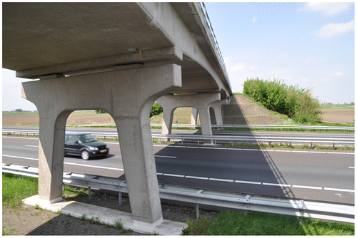
In this paper, the determination of the required load and the analysis of the measurements will be evaluated based on the pilot proof load test on the viaduct Zijlweg. The viaduct Zijlweg (Figure ) crosses the highway A59 in the province of Brabant, the Netherlands. It is a continuous reinforced concrete solid slab bridge of four spans with a 14.4° skew angle, and was built in 1965 for a design life of 80 years. The available information of the bridge includes the original design calculations, reports about the ASR damage and monitoring, and recent inspection reports, see Table .
Table 2. History of documentation of the viaduct Zijlweg.
The ASR damage was reported in 1997 (Rijkswaterstaat, Citation1997), together with a very small uniaxial tensile capacity and extensive cracking damage. As a result, the shear capacity was questioned, and an assessment for shear gave Unity Checks (ratio of shear stress caused by occurring loads to shear capacity) of up to 5.4, indicating a serious lack of shear capacity. A reassessment with a finite element model and a better estimate of the material properties brought the Unity Check down to maximum 1.31, indicating still insufficient shear capacity. Therefore, a proof load test as a pilot for the development of standards was carried out, in order to explore the feasibility of proof load testing at a shear-critical position. The viaduct was proof loaded on 17 June 2015.
3.2. State of viaduct Zijlweg prior to proof load test
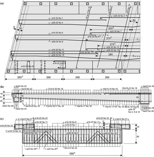
The viaduct Zijlweg crosses the A59 highway in the North-South direction. The lengths of the end spans are 10.32 m and of the mid spans 14.71 m (Figure (a)). The width of the viaduct is 6.60 m, with a carriageway of 4.00 m (Figure (b)) accommodating a single traffic lane. Sidewalks of 1.3 m are available on both edges of the width. The span subjected to proof loading is span 4, between supports 4 and 5 (Figure (a)), since this span is not directly above the highway, so that traffic restrictions are not necessary. The thickness of the slab varies from 550 mm at support 5 to 850 mm at support 4, with a radius of curvature of r = 150 m. The reinforcement in span 4 is shown in Figure .
Figure 2. Structural system of viaduct Zijlweg: (a) longitudinal section; (b) cross-section. Units: cm.
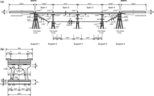
Figure 3. Reinforcement of viaduct Zijlweg: (a) top view; (b) side view; (c) transverse beam above abutments. Bar diameters in mm, all other dimensions in cm.
The concrete compressive strength is based on results of drilled cores (Witteveen+Bos, Citation2014), and is determined as fc,cube,m = 44.4 MPa (average cube compressive strength) and fck = 24.5 MPa (characteristic concrete cylinder compressive strength). The properties of the reinforcement steel are not available. The reinforcement drawings use symbols for plain bars, indicating that QR22 (with a characteristic yield strength fyk = 220 MPa) or QR24 (fyk = 240 MPa) was used.
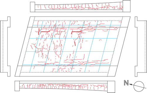
A visual inspection prior to the proof load test showed deterioration on the top deck, limited to the edge of the sidewalk, map cracking on the bottom of the slab, and an almost fully closed expansion joint as the result of the expansion by ASR. All cracks on the bottom and side faces were marked before the experiment, as presented in Figure .
3.3. Estimated capacity
One step that is suggested for the preparation of proof load tests, is to estimate the capacity of the bridge in order to evaluate the relation between the loads that will be applied and the estimated average capacity. Note that for this purpose all resistance factors are taken equal to one and the average expressions for the capacity are used. For bending moment, the behaviour and capacity are estimated by developing the moment-curvature diagrams, both for QR22 and QR24 steel. A good estimate for the average maximum load on slab bridges can be found with the Extended Strip Model (Lantsoght, van der Veen, de Boer, & Alexander, Citation2017). Since this calculation depends on the position of the load, it needs to be developed in parallel with the calculations for the development of the critical position of the load.
4. Determination of the target proof load
4.1. Current practice
For proof load testing on bridges, in the United States, the load of the vehicle for which the bridge needs to be rated through the load test is multiplied with a certain factor for the determination of the target proof load. The loading on the vehicle corresponds to the factored load, and the magnification factor used to find the target proof load is standard 1.4 (AASHTO, Citation2011; NCHRP, Citation1998). In the past, the proof load was taken as twice the maximum allowable load (Saraf, Nowak, & Till, Citation1996) to demonstrate safe performance of the bridge.
If proof load testing has as its goal to approve the passing of legal loads, a factor of 1.8 can be applied to the maximum legal load. The large loads required for proof load testing have been achieved by using military vehicles (Varela-Ortiz, Cintrón, Velázquez, & Stanton, Citation2010), by directly applying dead weights such as steel profiles on the bridge (Olaszek, Łagoda, & Casas, Citation2014), or by using an external structure (Schwesinger & Bolle, Citation2000). In Europe, no Eurocodes for the assessment of existing structures are available, and no vehicles for which bridges should be rated are available. Assessment of existing structures is done according to national codes. It has been suggested (Casas & Gómez, Citation2013) to use WIM data for the development of the required load factors for proof loading. These recommendations could be extended to consider all safety levels (Table ) defined in the Dutch national codes and guidelines, by repeating the calculations for all reliability indices considered in the Dutch national codes and guidelines. To abide to the codes, the load combinations from Table thus have to be applied.
4.2. Approach developed in the Netherlands
Since the load combinations from Table have to be used in the Netherlands, an equivalent proof load representing the factored live loads should be determined in addition to the permanent loads. The approach used in the Netherlands is based on the basic idea that the sectional moment or shear caused by the permanent loads and the proof load should be identical to the sectional moment or shear caused by the considered load combination. This analysis is based on a linear finite element model. In the Netherlands, the considered live loads are as defined by Load Model 1 from NEN-EN 1991-2:2003 (CEN, Citation2003), which describes a distributed lane load and a design tandem. The distributed lane load is placed over a notional lane width of 3 m, and should be applied in a checkerboard pattern to find the most unfavourable situation. Outside of the lanes, on the remaining parts of the carriageway, a distributed load of 2.5 kN/m2 is applied, and on the sidewalk a load of 5 kN/m2 corresponding to pedestrian loading is used,
For the design tandem, four wheel prints with 150 kN each distributed over 4 elements (distribution of wheel print of 400 mm × 400 mm to the slab mid-depth) are used. The tandem is centred in the notional lane of 3 m. When using a linear finite element model, the wheel print can be distributed under 45° to the slab mid-depth. For the proof load tandem, in practice, a wheel print of 230 mm × 300 mm is used, which needs to be modelled as well at the slab mid-depth.
To find the required magnitude and position of the proof load tandem for a proof load test verifying bending moment, the following procedure is used:
| (1) | All permanent loads and the loads from Load Model 1 are applied to the bridge, with their respective load factors. The position of the design tandems is moved along the span to find the position that results in the largest moment: the critical position. | ||||
| (2) | All permanent loads (with their respective load factors) and the proof load tandem (no load factor) are applied to the slab. The proof load tandem is placed at the critical position found from the previous analysis. The load on the proof load tandem is increased until the same value is found for the largest moment as from the previous analysis. The position and load magnitude are recorded for the load test. | ||||
A similar recommendation is developed to find the target proof load to test for shear. Instead of finding the maximum moment, the maximum shear is now sought and used as the governing criterion. The peak shear is distributed over 4d, with d the effective depth, as recommended when using linear finite element models for shear assessment (Lantsoght et al., Citation2013). The critical position is at 2.5d from the support (Rijkswaterstaat, Citation2013), as determined based on extensive experiments on slabs failing in shear (Lantsoght, van der Veen, de Boer, & Walraven, Citation2014; Lantsoght, van der Veen, de Boer, & Walraven, Citation2015; Lantsoght, van der Veen, & Walraven, Citation2013; Lantsoght, van der Veen, Walraven, & de Boer, Citation2015). The highest shear concentrations occur when loading at the obtuse corner (Cope, Citation1985), so that for skewed bridges the proof load tandem should be applied in the obtuse corner.
In the Netherlands, the research regarding proof load testing has focused so far on bridges with a small width (one or two lanes). For these cases, the loading case with a single proof load tandem is representative of the live loads. For wider viaducts, loading combinations should be compared as well. Wider viaducts are the topic of future research.
4.3. Verification with proof load test on viaduct Zijlweg
For the determination of the target proof load for the viaduct Zijlweg, a model using shell elements was developed in TNO DIANA (Citation2012). The slab was modelled as having a constant thickness, and the extra weight caused by the parts with a larger depth was added as an external load. For the viaduct Zijlweg, the thickness of the asphalt layer was taken as 10 cm. Since the viaduct carries less than 250,000 vehicles per year (category: regional road), the Dutch National Annex NEN-EN 1991-2/NA:2011 (Code Committee 351001, Citation2011b) prescribes a reduction factor of .97 for the live loads from Load Model 1 and of .90 for the remaining area of the lane. No reduction factor is used for the pedestrian traffic on the sidewalk.
Regarding bending moment, the critical face-to-face distance between the first axle of the tandem and the support is found as 3382 mm based on the procedure proposed in §4.2. The magnitude of the load on the proof load tandem depends on the considered safety level, see Table . An overview of the resulting maximum loads on the proof loading tandem is given in Table . It can be seen that a proof load of 128 metric ton is required. For shear, the position at 2.5d for the required face-to-face distance between the load and the support becomes 1208 mm, and the resulting loads necessary in the load test for shear are then shown in Table . For shear, the target proof load is 125 metric ton.
Table 3. Required maximum loads on the proof loading tandem at different safety levels.
The values for the target proof loads for shear and bending moment are considerably larger than the target proof loads that are applied in the United States, representing 1.4 times the vehicle, the bridge should be rated for. For these cases, target proof loads between 30 and 90 metric ton have been reported. However, these results are not directly comparable. In fact, the difference is because the live load factor in the AASHTO MBE has been calibrated taking into account the particular loading conditions existing in a proof load test, assuming that the self-weight and superimposed loads are perfectly known. Moreover, proof load testing for shear is a new development.
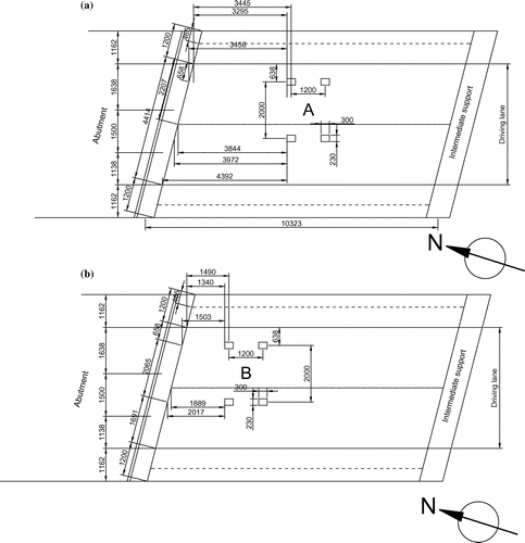
In the proof load test, the load is applied by placing heavy weights on a steel bridge over the actual concrete bridge, and by then transferring the load gradually by using jacks, see Figure for a step-by-step representation of how the loading system is built up. An overview of the positions of the jacks in each load test is shown in Figure . Every load level is applied three times to verify if the behaviour of the structure changes at the same load level, indicating non-linearity. Five load levels were defined: a low load level of 40 metric ton to verify the working of all sensors, the load corresponding to the Serviceability Limit State, two load steps building up to the final load and then the final load, corresponding to the safety level of 1.05 times RBK Design (Table ).
Figure 5. Setting up the loads for the proof load test: (a) application of jacks; (b) application of steel girders; (c) positioning of counterweights.
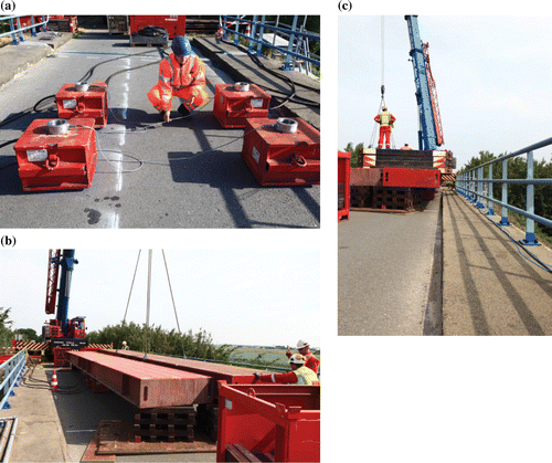
Figure 6. Positions of jacks during proof load tests: (a) bending moment position; (b) shear position.
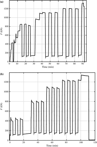
An extra 5% is added to cover uncertainties with regard to local variabilities in the structure, and the conversion of the Eurocode live loads to the proof load tandem. This factor can be considered as a model factor. In between the load cycles, a minimum load of 100 kN is applied, to keep all measurements activated. The loading schemes, as executed, are shown in Figure (a) for the bending moment position and in Figure (b) for the shear position. The maximum applied load during the bending moment test was 1332.4 kN. Additionally, the weight of the steel plate of 20.7 kN and jacks of 15.1 kN has to be added, resulting in a maximum applied load of 1368.2 kN. The maximum load in the shear test, including the weight of the steel plate and jacks was 1377.3 kN.
5. Determination of required measurements and stop criteria
5.1. Recommendations from current guidelines
The German guideline for load testing (Deutscher Ausschuss für Stahlbeton, Citation2000) uses a cyclic loading protocol of three load levels with at least one cycle per level. The first stop criterion limits the concrete strain:
(1)
The measured strain εc should be smaller than the limiting strain εc,lim (.8‰ if the compressive strength is larger than 25 MPa) minus the strain εc0 due to the permanent loads. The second criterion is a limiting strain in the steel, which prescribes that the measured strain εs2 should be smaller than a fraction of the yield strain (determined based on the mean yield strength of the steel fym and the Young’s modulus of the steel Es) minus the strain in the steel εs02 due to the permanent loads:(2)
The third criterion is based on the crack width w for new cracks and on the increase in crack width, Δw, for existing cracks: new cracks can maximum reach .5 mm, of which 30% residual crack width is allowed, and existing cracks can increase maximum to .3 mm, of which 20% residual crack width is allowed. The fourth acceptance criterion is that no non-linear behaviour can occur, typically evaluated on the load-deflection graph, or if more than 10% permanent deformation is found after removing the load. The fifth criterion limits the strains in the shear span of beams without shear reinforcement, and is thus not relevant for slabs. A test also needs to be stopped when the measurements indicate critical changes in the structure, when the stability of the structure is endangered, and when critical displacements occur at the supports.
The next set of stop criteria comes from ACI 437.2M-13 (ACI Committee 437, Citation2013), which allows monotonic and cyclic load tests for buildings. For the cyclic loading protocol, three load levels should be studied, with two cycles per load level. The first two cycles study the serviceability conditions, and the last two cycles study the full test load. The first stop criterion is that the structure should show no evidence of failure. The second stop criterion is the deviation from linearity index, IDL, with the angles α with respect to the origin of the load–displacement diagram:
(3)
The angle αi is the angle of the line through the origin of the load–displacement curve and the maximum of the i-th load cycle, whereas αref is the angle of the line through the origin of the load-displacement curve and the maximum of the first load cycle. The third acceptance criterion, the permanency ratio Ipr, is defined as:
(4)
where Ipi and Ip(i+1) are the permanency indexes calculated for the i-th and (i + 1)-th load cycles, based on the residual Δr and maximum Δmax deflections in the considered load cycles:
(5)
(6)
The third acceptance criterion requires that the residual deflection, Δr, measured at least 24 h after removal of the load, is maximum 25% of the maximum deflection or 1/180 of the span length.
5.2. Instrumentation of viaduct Zijlweg
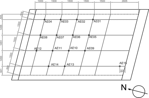
To verify the existing stop criteria, and to monitor the bridge behaviour carefully during proof load testing, a number of sensors were applied to the viaduct Zijlweg prior to the proof load test. The load effects that were measured during the test are: deformations of the deck, deformations of the cross-beams, crack width growths, strains, movements in the joint and rotations of the end support and acoustic emission signals (Yang & Hordijk, Citation2015). The interpretation of acoustic emission signals on existing bridges during proof load testing is a topic of ongoing research. For these measurements, 16 LVDTs, 6 laser distance finders and 15 acoustic emission sensors were used. The LVDTs and lasers used to measure the vertical deflections of the slab are shown in Figure (a). The LVDTs measuring strain over 1 m are shown in Figure (b). The lasers used for measuring the support deformations are shown in Figure (c).
Figure 8. Instrumentation on bottom of slab of viaduct Zijlweg: (a) LVDTs and lasers measuring vertical deflections; (b) LVDTs measuring strains; (c) lasers measuring support deflections, also showing the position of the jacks during the proof load tests.
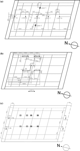
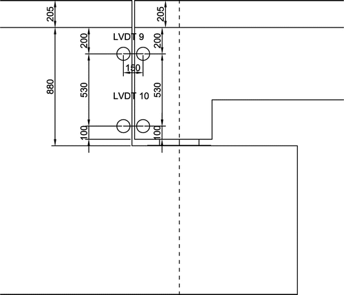
The movements in the joint and rotations of the end support are measured by two LVDTs on each side (east side and west side), as illustrated in Figure . An overview of the grid of acoustic emission sensors is given in Figure . The positions of the cracks that were monitored during the test are indicated in Figure . The longitudinal and transverse crack close to the support was monitored during the shear tests, whereas the longitudinal and transverse crack further in the span was monitored during the bending test. As such, for each test a longitudinal and transverse crack close to the position of the load is monitored. One of the LVDTs is used as a reference to correct the measurements for effect of temperature and humidity changes. This LVDT was applied on the abutment, and thus not affected by the structure’s response to load testing.
5.3. Measurements from viaduct Zijlweg
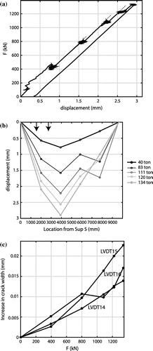
First, the post-processing of the measurements will be discussed, and in a next section the comparison to the stop criteria. The envelope of the load–displacement diagram from the proof load test to demonstrate sufficient bending moment capacity is shown in Figure (a). The load–displacement diagram is complemented with tangent lines, indicating slightly less stiff behaviour during the third and fourth increase of the load. This observation could be the result of redistribution of stresses, interaction between the loading frame and the bridge, possible friction in the joint, or the fact that the loading speed was lower in these steps. During unloading after the last loading step, the displacement was smaller than during the loading step, possibly caused by transverse stress redistribution or friction in the joint. These observations led to the recommendation to have a fixed loading speed for all load cycles.
Figure 11. Observations during the bending moment proof load test: (a) load-displacement diagram; (b) deflection in the longitudinal direction; (c) increase in crack width of existing cracks vs. force.
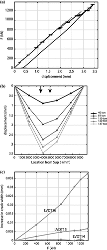
The profile of the longitudinal deflection for different loads during the experiment for bending moment is shown in Figure (b). The position of the two axles is indicated by arrows. These results are as expected, indicating increasing deflections for increasing loads. Finally, in Figure (c), the increase in crack width as a function of increased load is given. LVDT14 measured a crack on the side face that could develop into a shear crack, which was not activated during the test. LVDT15 and LVDT16 measured a longitudinal and transverse crack, respectively, on the bottom of the slab. The maximum increase in crack width was very small.
For the shear position, the envelope of the load–displacement diagram is shown in Figure (a). Until the maximum load, the measured behaviour was fully linear. The profiles of the deflection in the longitudinal direction are shown in Figure (b), in which LVDT8 had shifted out of its measurement range between loads of 600 and 1100 kN. Finally, the crack width measurements show a slight activation of the crack that could develop into a shear crack, and in general, very small increases in crack width, see Figure (c).
5.4. Analysis of stop criteria
The maximum deformation in the bending moment test δmax was 3.42 mm and the residual deformation was δresidual = .33 mm, so that the ratio δresidual/δmax = 9.7%, which is below the maximum 10%. The maximum deformation in the shear test δmax was 2.94 mm and the residual deformation was δresidual = .28 mm immediately after unloading and δresidual = .18 mm when all equipment was removed. The ratios are thus 9.7 and 6.1%, respectively, which both mean that the maximum value of 10% was not exceeded. The 25% residual deflection from ACI 437.2M-13 is obviously also achieved.
For the calculation of concrete strain, Equation (Equation1(1) ) is used. The strain caused by the permanent loads, εc0, is taken from the finite element programme. The results are given in Table . The difference in order of magnitude of the strains between LVDT1 and LVDTs 2 and 3 is explained by the fact that LVDT1 measures the strain in the transverse direction and LVDTs 2 and 3 in the longitudinal direction. The results of the maximum measured strains are given in Table as εc,max,meas, and the values corrected with the reference LVDT for temperature as εc,max. The value of εc.lim can be calculated with the recommended expression (Walraven, Citation2012) :
(7)
Table 4. Results of stop criterion of concrete strain for bending moment position.
The value of εc,max has to be smaller than εc,lim – εc0, a value which is given in the last column of Table . Therefore, the stop criterion for concrete strain is never exceeded during the test, both for the bending moment and shear tests.
For existing cracks, the German guideline prescribes a maximum increase in width Δw of .3 mm and a maximum residual crack width of .2 × Δw. The results are given in Table . It can be seen that the increase in crack width is small, and that the stop criterion for crack width is fulfilled for both the shear and bending moment positions. However, further research on control specimens in the laboratory is required to define the maximum allowable limits for crack width and increase in crack width, and to investigate if small crack widths can be neglected. The remaining stop criteria from ACI 437.2M-13 are not analysed here, because these stop criteria require that the loading scheme is exactly the same as the cyclic loading protocol described in the code. For testing the viaduct Zijlweg, more load steps were used.
Table 5. Results of stop criterion of increase in crack width for bending moment position.
6. Recommendations
6.1. Assessment of viaduct Zijlweg and suitability of proof load tests for ASR-affected viaducts
The proof load tests on the viaduct Zijlweg were successful to experimentally show that the bridge can carry its prescribed factored live loads. The moment and shear load tests corresponded to the safety level of RBK Design + 5% extra. The final conclusion for the viaduct Zijlweg itself is that the viaduct does not require posting. During the proof load experiment, there was no sign of distress in the measurements. This information is important, because the uniaxial tensile strength of the concrete in the viaduct is very low as a result of ASR-damage, so that the shear capacity of this viaduct was subject to discussion. The proof load test on the viaduct in the Zijlweg showed the important conclusion that the capacity of a viaduct affected by ASR is still sufficient for the current traffic as prescribed by the live load model from NEN-EN 1991-2:2003 (CEN, Citation2003). The problem of the small strength of the concrete in uniaxial tension is thus of a lower magnitude than feared, and similar tests can be recommended to experimentally approve other ASR-affected viaducts, or viaducts where the uncertainties related to material degradation are large.
6.2. Lessons learned for the development of guidelines for proof load testing
For the determination of the target proof load, the presented method which is based on equivalent sectional shears or moments caused by the proof load tandem and the considered live loads can be recommended. The use of a single proof load tandem can be recommended for viaducts with a small width. For wider viaducts, a combination of proof load tandems or loading vehicles needs to be explored.
When assessing the stop criteria, the physical significance should never be forgotten. As can be seen from Table , very small values for the maximum crack widths are found. A threshold value below which the crack width can be considered as zero should be defined. A proposed value is wmin = .05 mm. The problem with using a value such as a ‘residual deflection’ and ‘residual crack width’ after each loading step is that the load has to be constant. This load could be 0, but for practical purposes always a low load level has to be maintained so that all measurements stay activated, for example 100 kN. Returning to this load level of exactly 100 kN when using a system based on jacks is not easy in practice. Therefore, stop criteria that combine both the effect of the applied load and the structural response are to be preferred. The stop criterion related to the steel strains, i.e. Equation (Equation2(2) ), cannot be recommended for practical purposes, as it requires removal of the concrete cover, which is something not all bridge owners would allow for a non-destructive test such as a proof load test. The analysis of the measurements shows that following the load–displacement diagram and the plots of the deformations in the longitudinal and transverse directions is important to identify possible non-linear behaviour. Defining clear stop criteria is a topic of current research.
Finally, the method present in this article can be applied to reinforced concrete slab bridges. Slab bridges typically show signs of distress, even before a brittle shear failure. For more brittle structural types, such as prestressed girder bridges, a further experimental validation of stop criteria will be necessary.
7. Conclusions
Load testing is part of the standard engineering practice. However, one form of load testing, proof load testing, is less common. This type of testing allows direct experimental approval of a bridge if it can carry its factored live loads without significant signs of distress. If signs of distress occur prior to reaching the target proof load required to show adequate performance of the bridge, the bridge can be approved for the last load level that could be sustained without significant signs of distress. If this last load level is lower than the minimum safety requirements, posting or strengthening of the bridge may be necessary. Note that these minimum safety requirements should be calculated with a live load factor calibrated with the same target value of the reliability index as appears in Table , but considering the nominal values of self-weight, as this value has now become a deterministic value. This decision, however, needs to be taken by the bridge owner. Proof load tests are typically not allowed for shear-critical situations. Because a large number of the existing reinforced concrete slab bridges in the Netherlands rate insufficiently for shear, proof load testing for shear needs to be developed. A pilot proof load test was carried out to evaluate the applicability of existing procedures, and to highlight the areas that need further research. In particular, guidelines for reinforced concrete slab bridges need to be developed.
One important area is to determine the required target proof load. Whereas in practice in the U.S.A this load is (typically) 1.4 times the load of the design truck the bridge needs to be rated for, in Europe, rating and assessment is not carried out based on a set of standard vehicles, but by using the regular live load models, or by following national recommendations. These models consist of combined distributed lane loads and concentrated live loads. Therefore, it is proposed here to find the target proof load as the load that causes the same sectional moment or shear as the factored live loads from the code. For bending moment, the critical position is found by moving the design tandems in their respective lane, and finding the largest bending moment. The critical position for shear is taken at 2.5d, as was determined from tests on half-scale slab bridges in the laboratory, and at the obtuse corner. The viaduct Zijlweg was successfully tested at these two positions, showing that proof load testing for reinforced concrete slab bridges is feasible and can be used to demonstrate that the considered bridge can carry the prescribed live loads without significant distress. It is important to point out that this ASR-affected viaduct was difficult to assess analytically, as the effect of ASR on the shear capacity is currently not well-understood.
A second important topic is the measurements and stop criteria. Current codes and guidelines only prescribe stop criteria for bending moment. From the analysis of this pilot test, it was found that the deviation from linearity index and the permanency ratio are strongly dependent on the prescribed loading protocol, and cannot be applied directly to the loading protocol followed in this pilot test. The analysis also showed that measuring steel strains is not practical, as it requires removal of the concrete cover, which many bridge owners do not allow. The stop criterion for the concrete strain was found to be interesting, as well as the criterion for the crack width and increase in crack width, provided that a lower bound of crack width is added to these considerations. Additionally, when loads are applied through hydraulic jacks and cannot be controlled very accurately, it can be recommended to develop stop criteria that contain both the load and the structural response.
This pilot proof load test on a reinforced concrete slab bridge with material damage shows that proof load testing can be used for the assessment of such bridges. It is shown that proof load testing for shear is possible. For practical application, the stop criteria need to be defined for both shear and flexure. Some useful stop criteria have been identified based on this pilot test, and research on beams cast in the laboratory will further define and identify suitable stop criteria.
Notations list
The following symbols are used in this paper:
| d | = | the effective depth |
| fc,cube,m | = | the average cube compressive strength |
| fck | = | the characteristic concrete cylinder compressive strength |
| fyk | = | the characteristic yield strength |
| fym | = | the average yield strength |
| r | = | the radius of curvature |
| w | = | the crack width |
| wmin | = | the crack width below which the crack width can be neglected |
| Es | = | the Young’s modulus of the steel |
| F | = | the load |
| Ftot | = | the maximum required load on the proof load tandem to approve a bridge for a certain safety level |
| IDL | = | the deviation from linearity index |
| IPi | = | the permanency index of the i-th load step |
| IPR | = | the permanency ratio |
| αi | = | the angle formed by the line between the origin and the loading point |
| αref | = | the angle of the load–displacement diagram of the first cycle |
| β | = | the reliability index |
| δ | = | the measured deformation |
| δmax | = | the maximum deformation |
| δresidual | = | the residual deformation |
| εc | = | the measured strain in the concrete |
| εc,lim | = | the limiting concrete strain |
| εc,max,meas | = | the maximum measured concrete strain |
| εc,max | = | the governing maximum concrete strain |
| εc0 | = | the strain caused by the permanent loads |
| εs2 | = | the strain in the steel |
| εs02 | = | the strain in the steel caused by the permanent loads |
| ρc | = | the density of concrete |
| Δw | = | the increase in crack width of an existing crack |
| = | the residual deflection (non-cumulative) after the i-th load cycle | |
| = | the maximum deflection after the i-the load cycle |
Disclosure statement
No potential conflict of interest was reported by the authors.
Acknowledgements
The authors wish to express their gratitude and sincere appreciation to the Dutch Ministry of Infrastructure and the Environment (Rijkswaterstaat) and the Province of Noord Brabant for financing this research work. The contributions and help of our colleagues Albert Bosman, Cor van der Veen, and Yuguang Yang, and students Arthur Ennouri and Werner Vos of Delft University of Technology, of Witteveen+Bos, responsible for the logistics and safety, and of Mammoet, responsible for applying the load, are gratefully acknowledged. The fruitful discussions with Frank Linthorst and Danny den Boef of Witteveen+Bos and with Otto Illing and the late Chris Huissen of Mammoet are acknowledged.
References
- AASHTO. (2011). The manual for bridge evaluation. (2nd ed.). Washington, DC: American Association for State Highway and Transportation Officials.
- ACI Committee 437. (2013). Code requirements for load testing of existing concrete structures (ACI 437.2M-13) and commentary (p. 24). Farmington Hills, MA: American Concrete Institute.
- Ahmed, T., Burley, E., & Rigden, S. (1998). The static and fatigue strength of reinforced concrete beams affected by alkali-silica reaction. ACI Materials Journal, 95, 376–388.
- Ahmed, T., Burley, E., & Rigden, S. (1999). Effect of alkali-silica reaction on tensile bond strength of reinforcement in concrete tested under static and fatigue loading. ACI Materials Journal, 96, 419–428.
- Borsje, H., Peelen, W. H. A., Postema, F. J., & Bakker, J. D. (2002). Monitoring alkali-silica reaction in structures. Heron, 47, 96–109.
- Casas, J. R., & Gómez, J. D. (2013). Load rating of highway bridges by proof-loading. KSCE Journal of Civil Engineering, 17, 556–567.10.1007/s12205-013-0007-8
- CEN. (2003). Eurocode 1: Actions on structures – Part 2: Traffic loads on bridges, NEN-EN 1991-2:2003 (p. 168). Brussels: European Normalization Institute.
- CEN. (2005). Eurocode 2: Design of concrete structures – Part 1-1 general rules and rules for buildings. NEN-EN 1992-1-1:2005 (p. 229). Brussels: European Normalization Institute.
- Code Committee 351001. (2011a). Assessement of structural safety of an existing structure at repair or unfit for use – Basic requirements, NEN 8700:2011. Delft, The Netherlands: Civil Center for the Execution of Research and Standard, Dutch Normalisation Institute (in Dutch).
- Code Committee 351001. (2011b). Eurocode 1 – Actions on structures – Part 2: Traffic loads on bridges, EN 1991-2/NA:2011 (p. 38). Delft, The Netherlands: Civil Engineering Center for Research and Regulation, Dutch Normalization Institute.
- Cope, R. J. (1985). Flexural shear failure of reinforced-concrete slab bridges. Proceedings of the Institution of Civil Engineers Part 2-Research and Theory, 79, 559–583.
- Davids, W. G., Poulin, T. J., & Goslin, K. (2013). Finite-element analysis and load rating of flat slab concrete bridges. Journal of Bridge Engineering, 18, 946–956.10.1061/(ASCE)BE.1943-5592.0000461
- den Uijl, J. A., & Kaptijn, N. (2002). Structural consequences of ASR: An example on shear capacity. Heron, 47(2), 1–13.
- Deutscher Ausschuss für Stahlbeton. (2000). DAfStb-guideline: Load tests on concrete structures (p. 7). DAfStB (in German).
- fib. (2012). Model code 2010: Final draft. Lausanne: International Federation for Structural Concrete.
- Giaccio, G., Zerbino, R., Ponce, J. M., & Batic, O. R. (2008). Mechanical behavior of concretes damaged by alkali-silica reaction. Cement and Concrete Research, 38, 993–1004. doi:10.1016/j.cemconres.2008.02.009
- Haddad, R. H., Shannag, M. J., & Al-Hambouth, M. T. (2008). Repair of reinforced concrete beams damaged by alkali-silica reaction. ACI Structural Journal, 105, 145–153.
- Koekkoek, R., Lantsoght, E., Yang, Y., Boer, A. D., & Hordijk, D. (2016). Defining loading criteria for proof loading of existing reinforced concrete bridges. Paper presented at the fib symposium 2016: Performance-based approaches for concrete structures, Cape Town, South Africa.
- Koenders Instruments. (2015). Zijlweg monitoring system (p. 4). Alkmaar: Koenders Instruments.
- Lantsoght, E. O. L., de Boer, A., & van der Veen, C. (2017). Levels of approximation for the shear assessment of reinforced concrete slab bridges. Structural Concrete, 18, 143–152.10.1002/suco.201600012
- Lantsoght, E. O. L., Van der Veen, C., de Boer, A., & Hordijk, D. A. (2016). Collapse test and moment capacity of the Ruytenschildt reinforced concrete slab bridge. Structure and Infrastructure Engineering, 13, 1130–1145. doi:10.1080/15732479.2016.1244212
- Lantsoght, E. O. L., de Boer, A., Van der Veen, C., & Walraven, J. C. (2013). Peak shear stress distribution in finite element models of concrete slabs. Paper presented at the Research and Applications in Structural Engineering, Mechanics and Computation, Cape Town, South Africa.
- Lantsoght, E. O. L., van der Veen, C., de Boer, A., & Alexander, S. D. B. (2017). Extended strip model for slabs under concentrated loads. ACI Structural Journal, 114, 565–574.
- Lantsoght, E. O. L., van der Veen, C., de Boer, A., & Walraven, J. (2014). Influence of width on shear capacity of reinforced concrete members. ACI Structural Journal, 111, 1441–1450.
- Lantsoght, E. O. L., van der Veen, C., de Boer, A., & Walraven, J. (2015). One-way slabs subjected to combination of loads failing in shear. ACI Structural Journal, 112, 417–426.
- Lantsoght, E. O. L., van der Veen, C., Walraven, J., & de Boer, A. (2013). Recommendations for the shear assessment of reinforced concrete slab bridges from experiments. Structural Engineering International, 23, 418–426.10.2749/101686613X13627347100239
- Lantsoght, E. O. L., van der Veen, C., Walraven, J., & de Boer, A. (2015). Experimental investigation on shear capacity of reinforced concrete slabs with plain bars and slabs on elastomeric bearings. Engineering Structures, 103, 1–14.10.1016/j.engstruct.2015.08.028
- Lantsoght, E. O. L., van der Veen, C., & Walraven, J. C. (2013). Shear in one-way slabs under a concentrated load close to the support. ACI Structural Journal, 110, 275–284.
- NCHRP. (1998). Manual for bridge rating through load testing (Vol. NCHRP Project 12-28(13)A, p. 152). Washington, DC: National Cooperative Highway Research Program.
- Neville, A. (2012). Properties of concrete. (5th ed.). Harlow: Pearson Education.
- Nijland, T. G., & Siemes, A. J. M. (2002). Alkali-silica reaction in the Netherlands: Experiences and current research. Heron, 47, 81–84.
- Olaszek, P., Łagoda, M., & Casas, J. R. (2014). Diagnostic load testing and assessment of existing bridges: Examples of application. Structure and Infrastructure Engineering, 10, 834–842.10.1080/15732479.2013.772212
- Provincie Noord Brabant. (1965). Viaduct Zijlweg (p. 12). ‘s Hertogenbosch, The Netherlands (in Dutch).
- Rijkswaterstaat (1997). Safety evaluation of existing structures – Reinforced concrete bridges (p. 102). Utrecht: (Ministry of Infrastructure and the Environment in Dutch).
- Rijkswaterstaat. (2002). Management- and maintenance plan Viaduct Zijlweg of highway A59 (p. 36). Utrecht, The Netherlands (in Dutch).
- Rijkswaterstaat. (2008). Inspection report of object 44G-113-01 (p. 26). Utrecht, The Netherlands (in Dutch).
- Rijkswaterstaat. (2012). Guidelines for nonlinear finite element analysis of concrete structures (p. 65). RTD 1016:2012, Utrecht, The Netherlands.
- Rijkswaterstaat. (2013). Guidelines assessment bridges – Assessment of structural safety of an existing bridge at reconstruction, usage and disapproval (p. 117). RTD 1006:2013, Utrecht, The Netherlands (in Dutch).
- Saraf, V. K., Nowak, A. S., & Till, R. (1996). Proof load testing of bridges. Paper presented at the Probabilistic Mechanics & Structural Reliability: Proceedings of the Seventh Specialty Conference, Worcester, MA, USA.
- Schacht, G., Bolle, G., Curbach, M., & Marx, S. (2016). Experimental evaluation of the shear bearing safety. Beton- und Stahlbetonbau, 111, 343–354 (in German).10.1002/best.v111.6
- Schmidt, J. W., Hansen, S. G., Barbosa, R. A., & Henriksen, A. (2014). Novel shear capacity testing of ASR damaged full scale concrete bridge. Engineering Structures, 79, 365–374. doi:10.1016/j.engstruct.2014.08.027
- Schwesinger, P., & Bolle, G. (2000). EXTRA – A new experiment supported condition assessment method for concrete bridges. Paper presented at the Proceedings of SPIE 3995, Nondestructive Evaluation of Highways, Utilities, and Pipelines IV.
- Siemes, T., Han, N., & Visser, J. (2002). Unexpectedly low tensile strength in concrete structures. Heron, 47, 111–124.
- Steenbergen, R. D. J. M., de Boer, A., & van der Veen, C. (2011). Safety assessment of existing concrete slab bridges for shear capacity. Paper presented at the Applications of Statistics and Probability in Civil Engineering, Zürich, Switzerland.
- Talley, K. G. (2009). Assessment and strengthening of ASR and DEF affected concrete bridge columns (PhD thesis). UT Austin, Austin, TX.
- TNO DIANA. (2012). DIANA users manual, Release 9.4.4. Delft, The Netherlands.
- Varela-Ortiz, W., Cintrón, C. Y. L., Velázquez, G. I., & Stanton, T. R. (2010). Load testing and GPR assessment for concrete bridges on military installations. Construction and Building Materials, 38, 1255–1269.
- Vergoossen, R., Naaktgeboren, M., ‘t Hart, M., de Boer, A., & Van Vugt, E. (2013). Quick scan on shear in existing slab type viaducts. Paper presented at the International IABSE Conference, Assessment, Upgrading and Refurbishment of Infrastructures, Rotterdam, The Netherlands.
- Walraven, J. C. (2012). Proof loading of concrete bridges (Stevin Report 25-5-2012). Delft: Delft University of Technology (in Dutch).
- Witteveen+Bos. (2014). Material research bridges case 31084913: 44G-113-01 – viaduct Zijlweg (p. 23). Deventer.
- Yang, Y., & Hordijk, D. A. (2015). Acoustic emission measurement and analysis on Zijlwegbrug (Stevin Report 25.5-15-01, p. 27). Delft, The Netherlands: Delft University of Technology.

