
Abstract
This paper proposes a pixel structure and a hybrid driving method for improving the transmittance of the liquid crystal display (LCD) for the outdoor public information display (PID) while maintaining the image quality. The proposed driving method uses the pixel consisting of subpixels using red (R), green (G), and blue (B) color filters and white (W) subpixels, and performs in either of two operation modes selected according to the amount of sunlight and the temperature. Mode 1 is a hybrid field sequential mode in which W subpixels are operated to increase the transmittance without the simultaneous contrast problem under the very bright condition. Mode 2 is a low-temperature mode in which only red–green–blue (RGB) subpixels are operated to prevent image distortion under a low-temperature condition. The measurement results from the fabricated LCD were 14.5% transmittance, an over 4000 contrast ratio, and 82.5% color gamut. In addition, the ratio of RGB luminance to the W image is similar to that of the conventional LCD. Therefore, the proposed pixel structure and driving method are appropriate for outdoor PIDs.
Introduction
A digital signage using liquid crystal display (LCD), called ‘public information display (PID)’, has gained much attention of late. Many advertising agencies and information providers are replacing static displays such as the paper and plastic ones with PIDs to provide dynamic advertisements, messages, and digital contents. Accordingly, PID has become a more effective tool of communicating with the customers, as an outdoor digital signage, and has been widely deployed in many public places, such as bus stops, shopping malls, quick-service restaurants, and airports.
Generally, however, PID is used under various environmental conditions that cause degradation of the image quality. For example, the display image quality is directly affected by the amount of sunlight. When PID is exposed to sunlight, the image on the display panel will look rather dim, and as such, a brighter LCD is necessary for outdoor digital signages. The brightness of the LCD is correlated with the luminance of a backlight (BLU) and the transmittance of a panel. Therefore, the brightness of the LCD can be increased by increasing the BLU luminance, but this will also increase the total power consumption.
To solve the aforementioned problem, several methods have been researched on to increase the transmittance of the display panel without increasing the power consumption. One method is to use the field sequential liquid crystal display (FS-LCD), which has good light efficiency without optical loss from color filters (CFs). Using FS-LCD generally improves the transmittance threefold compared with that of the conventional thin-film-transistor liquid crystal display (TFT-LCD) [Citation1–3]. Due to the slow response time of liquid crystal (LC) at a low temperature, however, FS-LCD is inappropriate for PID. The other method of increasing the transmittance of the display panel without increasing the power consumption is to add a white (W) subpixel to improve the transmittance of the LCD [Citation4–9]. The LCD using the red–green–blue–white (RGBW) pixel structure is much brighter than that using the red–green–blue (RGB) pixel structure because the transmittance is increased by the added white (W) subpixel. During the reproduction of the saturated color, however, the red (R), green (G), and blue (B) colors are perceived to be darker because the transmittance of the RGB subpixel is decreased, which causes the simultaneous contrast problem [Citation5]. Therefore, a method of increasing the transmittance of the display panel without image distortion should be considered to improve the image quality of the outdoor PID.
Presented in this paper are a pixel structure and its driving method for increasing the transmittance of the LCD for the outdoor PID. The simultaneous contrast problem is solved by applying the field sequential (FS) driving method to the W subpixel, which is added to the conventional TFT-LCD using the RGB light-emitting diode (LED) BLU. The second section describes the structure of the proposed pixel with a detailed explanation of the added W subpixel. In the third section, the proposed hybrid driving method with two operation modes used depending on the environmental conditions is presented. The measurement results of the fabricated PID using the proposed pixel structure are analyzed and summarized in the fourth section. Finally, the conclusions are presented in the fifth section.
Proposed pixel structure
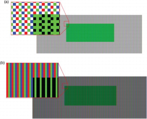
For the outdoor PID, the LCD must have sufficiently high brightness so that the display image can be perceived. Proposed herein is a new pixel structure with a W subpixel that can increase the transmittance of the LCD panel, as shown in (a). The proposed PID employs the pixel structure with double data lines and two transistors presented in [Citation10]. One of the subpixels was replaced with a W subpixel by rearranging the CF, and then simulation was performed using MATLAB to check the image quality. Depending on the set location of the W subpixel, the luminance of the line with the RGB subpixel is different from the luminance of the line with the W subpixel. To reduce the difference in luminance, the W subpixel was made to assume a mosaic pattern. As shown in , image simulation of the proposed RGBW pixel structure was performed, and such a structure was compared with that of the conventional RGB pixel structure. The simulation results show that the LCD using the proposed pixel structure has a higher transmittance than the conventional pixel structure. As the area of the RGB subpixel was reduced by half, the luminance was likewise reduced by half, but the W subpixels increased the luminance threefold compared with the RGB subpixel. As a result, the total transmittance of the proposed pixel structure increased twofold compared with that of the conventional RGB subpixel. Therefore, the proposed pixel structure is appropriate for the outdoor PID.
Figure 1. Structure of (a) the proposed RGBW pixel and (b) the conventional RGB pixel.
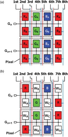
Figure 2. Simulation results of an image using (a) the proposed RGBW pixel and (b) the conventional RGB pixel. The simulated image is a green box (100 × 50 pixels) on a white background (200 × 100 pixels).
Proposed hybrid driving method with two operation modes
The proposed pixel structure is driven in either of two operation modes according to the environmental conditions. One is the hybrid FS (H-FS) mode, in which the FS driving method for the W subpixel and the conventional driving method for the RGB pixel are applied to PID to reduce the simultaneous contrast problem. The other is the low-temperature mode to prevent image distortion caused by the slow response time of LC at the low-temperature condition during nighttime or the cold season.
H-FS operation mode
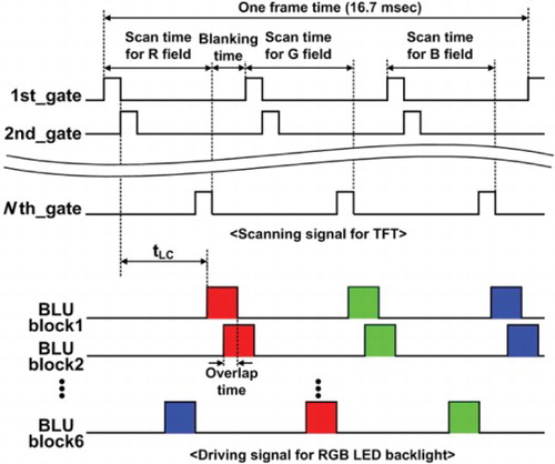
In the RGBW pixel structure, the luminance of the W subpixel is increased, and the luminance of the RGB subpixel is decreased, which causes the simultaneous contrast problem. To solve this problem, the 180 Hz RGB FS driving method using an LED BLU is applied to the W subpixels. The FS driving method, however, has a color break-up (CBU) problem and needs a fast-response LC cell. The CBU is an artifact of separated color components in a color image, which is caused by a relative velocity difference between the object on the FS-LCD and the human eyes. To reduce the CBU problem, the commercial frame rate conversion IC was used to generate the RGB subfield image with the motion estimation and motion compensation method [Citation11] employed in the proposed PID. Also, a fast-response LC cell was used to implement the proposed PID. The rising and falling times between the black and white states were less than 4 ms. In addition, the overdriving method [Citation12] was used to reduce the response time of the gray to gray pattern within one frame time. shows the timing diagram of the scanning signal for the TFT and the driving signal for the RGB LED BLU. The scanning signal is sequentially operated with one scan time (4.1 ms) per color field, and the scanning signal with respect to each color field is separated by the blanking time (1.5 ms). The driving signal for BLU turns on the selected BLU block according to the scanning signal after the response time of LC (tLC), and is then turned off just before the scanning signal of the next color field is turned on. The LED BLU is divided into six blocks (BLU block 1–6) to consider the response time difference according to the position of the LC cell, and the driving time with the adjacent BLU blocks is overlapped to increase the luminance of the PID.
Figure 3. Timing diagram of the scanning signal for the TFT of the proposed PID, and of the driving signal for the RGB LED BLU.
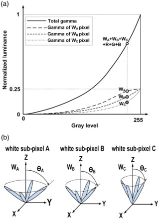
To improve the viewing angle property in the vertical-alignment LC mode, two or three subpixels for each color are located in one pixel, and different voltages are applied at the same gray level to form the multidomain presented in [Citation10,Citation13]. In the proposed pixel structure, W subpixels were used to form the multidomain because the proposed pixel structure has one subpixel for each RGB color, and a different gamma curve was applied to each W subpixel so that the LC molecules would have a different tilting angle according to the voltage applied at the same gray level, as shown in . Accordingly, the LC molecules in the W subpixels compensate for and minimize the gamma distortion for the images viewed from the off-axis gamma. As a result, the proposed pixel structure achieves the wide viewing angle property of the outdoor PID.
Figure 4. (a) Gamma curves for each W subpixel and for the total. (b) Motion of LC for each W subpixel according to the applied gamma curve at the same gray level.
Low-temperature operation mode
The outdoor PID usually stays turned on all day under various environmental conditions. The ambient lighting condition and temperature are varied through the day and night over the year. The H-FS mode properly operates under the bright lighting condition and warm temperature while image distortion occurs due to the slow response time of LC at a low temperature. The response time of the LC cell is calculated as
(1)
where d, γ1, K, Vth, and V are the cell gap of the LC layer, the rotational viscosity, the averaged elastic constant, the threshold voltage of the LC material, and the voltage applied to the LC cell, respectively. Among these parameters, γ1 and K are largely dependent on the temperature. shows the relative value of γ1 and K with respect to the temperature. The LC cell has a long transition time because of the γ1/K parameter, and the response time of the LC cell increases as the temperature decreases. Accordingly, the FS driving method does not properly work, and the color mixing artifact occurs in the W subpixel. To solve the aforementioned problem, the proposed driving method, which uses only the RGB subpixel to display the color image, is operated under a low temperature, as shown in . As the color generated by the RGB CF is not affected by the response time of the LC cell, the proposed PID using only RGB subpixels operates normally without a color mixing artifact at the low-temperature mode.
Figure 5. Relative value of the rotational viscosity and the averaged elastic constant.
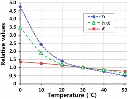
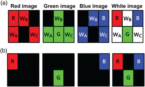
Figure 6. Status of the R, G, B, and W images in the (a) H-FS operation mode and (b) low-temperature operation mode.
Measurement results
The outdoor PID using the proposed pixel structure and its driving method were applied to a 15.6-inch LCD panel for experimental verification, and were successfully demonstrated as shown in . The demonstrated LCD using the proposed pixel structure was normally operated as shown in the enlarged area of ; the fabricated LCD looks spotted on the left side in the picture because it was fabricated through an unstable experimental process. In particular, the proposed driving method at the H-FS mode was verified by confirming the operation of the W subpixels of the green image. The performances of the fabricated PID, such as its transmittance, contrast ratio, and color gamut, were measured according to the operation mode. The measurement results of the color gamut of the fabricated FS-LCD in the CIE1931 color coordinate are shown in , and the transmittance and contrast ratio according to the operation mode are summarized in Table .
Figure 7. Picture of the PID fabricated using the proposed pixel structure.
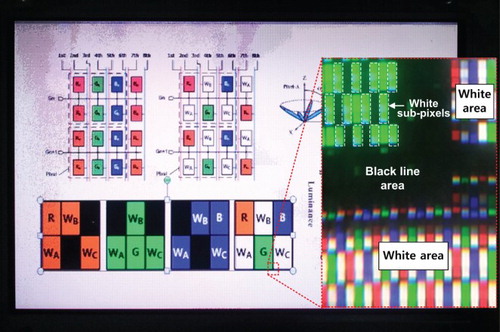
Figure 8. Measured color gamut of the fabricated FS-LCD in the CIE1931 color coordinate.
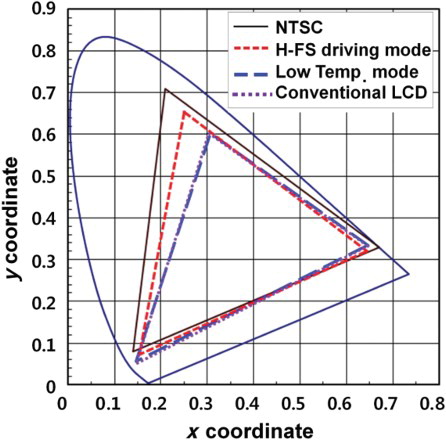
Table 1. Transmittance and contrast ratio.
In the H-FS mode, the fabricated PID using the proposed pixel structure shows higher transmittance and a wider color gamut compared with the conventional PID. The measured transmittance is more than twice higher than that of the conventional PID because of the added W subpixels and the fact that there is no optical loss from CFs, whereas the measured contrast ratio has a similar value because the black luminance increases as the transmittance increases. As the transmittance of the LCD panel increases, the power consumption is reduced by a ratio of the increased transmittance with the same brightness, or the luminance increases by a ratio of the increased transmittance with the same power consumption. For this reason, the fabricated PID system consumes 50% less power with the same brightness, or has twice higher luminance with the same power consumption compared with the conventional PID. Also, the measured color gamut of the fabricated PID is wider than that of the conventional PID. The color gamut of the conventional PID is determined by the transmission spectrum of the CF. The CFs only transmit the light received from the BLU in accordance with the wavelength of their own color, and block the other colors. As CFs cannot perfectly block the other colors, however, the color gamut of the conventional PID decreases. On the other hand, in the H-FS mode of the fabricated PID, which is operated with RGB and W subpixels, the fabricated PID represents the color using the light transmitted through the RGB and W subpixels. As W subpixels directly transmit the light received from the RGB LED BLU, which has a very wide color gamut (over 110% of the NTSC color standard) [Citation14], the H-FS mode has a wider color gamut compared with the conventional PID.
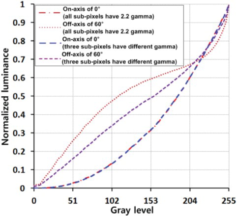
In addition, as the difference between the on- and off-axis gammas causes image distortion in the off-axis, the on- and off-axis gammas were measured to verify the viewing angle characteristics. As shown in , three different gammas depicted as dots were applied to the W subpixels to reduce the image distortion in the off-axis gamma. As a result, the image distortion due to the off-axis gamma was greatly reduced in the proposed PID. shows the on- and off-axis gamma curves of the fabricated PID according to the viewing angle and the controlled gamma. These results indicate that the viewing angle characteristic of the fabricated PID was improved by the applied gamma according to the LC motion of each W subpixel.
Figure 9. Normalized luminance of the fabricated PID at the on- and off-axis gammas.
In the low-temperature mode, the fabricated PID has a lower transmittance and contrast ratio values because it operates with only RGB subpixels. The W luminance is reduced by half as the RGB subpixel area is likewise reduced by half, whereas the black luminance has the same value as in the H-FS mode. Accordingly, the measured contrast ratio is decreased in the low-temperature mode. As a result, both the transmittance and the contrast ratios are decreased in the low-temperature mode. The measured color gamut of the proposed PID, however, has a similar value as that of the conventional LCD because these two displays use the same CF.
As summarized in , the measured relative ratio of RGB luminance to the W color shows that the proposed PID improves the transmittance without any simultaneous contrast problem.
Table 2. Relative ratio of RGB luminance to the W color.
Conclusion
A novel pixel structure and its driving method are proposed herein to improve the transmittance of the LCD for the outdoor PID, and it was applied to an LCD panel. The proposed pixel, which consists of RGB CFs and white (W) subpixels, is driven in two operation modes according to various environmental conditions, such as the sunlight illumination and the temperature. Mode 1 is the H-FS mode for improving the transmittance without the simultaneous contrast problem, and mode 2 is the low-temperature mode to prevent image distortion caused by the slow response time of LC at the low-temperature condition during nighttime or the cold season. Therefore, the proposed PID can be used under extreme sunlight and a wide temperature range, including a low-temperature environment, without image distortion. Compared with the conventional LCD products, the proposed hybrid driving method increases the total luminance about twofold without additional power consumption. The fabricated PID has 14.5% transmittance and a wide color gamut (82.5%). These results indicate that the proposed pixel structure and its driving method are appropriate for the outdoor PID.
References
- H. Hasebe and S. Kobayashi, presented at the SID International Symposium, Sheraton-Twin Towers, Orlando, FL, 1985.
- F. Yamada, H. Nakamura, Y. Sakaguchi, and Y. Taira, J. Soc. Inf. Disp. 10 (1), 81–85 (2002). doi: 10.1889/1.1827848
- J.H. Kwon, J. Inf. Disp. 10 (2), 45–48 (2010). doi: 10.1080/15980316.2010.9652118
- B.W. Lee, C. Park, S. Kim, T. Kim, Y. Yang, J. Oh, J. Choi, M. Hong, D. Sakong, K. Chung, S. Lee, and C. Kim, presented at the SID International Symposium, Baltimore Convention Center, Baltimore, MD, 2003.
- B.W. Lee, K. Song, Y. Yang, C. Park, J. Oh, C. Chai, J. Choi, N. Roh, M. Hong, K. Chung, S. Lee, and C. Kim, presented at the SID International Symposium, Washington State Convention Center, Seattle, WA, 2004.
- C.H.B. Elliott, T.L. Credelle, and M.F. Higgins, Inf. Disp. 21 (5), 26–30 (2005).
- C.C. Lai and C.C. Tsai, IEEE Trans. Consum. Electron. 53 (4), 1628–1633 (2007). doi: 10.1109/TCE.2007.4429262
- S. Wen, J. Inf. Disp. 10 (4), 164–170 (2009). doi: 10.1080/15980316.2009.9652101
- M. Hammer and K.J.G. Hinnen, IEEE J. Disp. Technol. 10 (1), 33–42 (2014). doi: 10.1109/JDT.2013.2278985
- S.S. Kim, presented at the SID International Symposium, Hynes Convention Center Station, Boston, MA, 2005.
- N. Koma and T. Uchida, J. Soc. Inf. Disp. 11 (2), 413–417 (2003). doi: 10.1889/1.1825656
- B. Lee, C. Park, S. Kim, M. Jeon, J. Heo, D. Sagong, J. Kim, and J. Souk, presented at the SID International Symposium, San Jose Convention Center, San Jose, CA, 2001.
- S.J. Kim, K.C. Shin, H. Kim, H.G. Oh, J.H. Jung, and H.S. Kim, J. Inf. Disp. 14 (3), 93–96 (2013). doi: 10.1080/15980316.2013.837843
- W. Huanga, J.M. Lia, L.M. Yanga, Z.L. Jina, Z.G. Zhonga, Y. Liua, Q.Y. Choua, and F. Li, Opt. Laser Technol. 11 (1), 214–217 (2011). doi: 10.1016/j.optlastec.2010.06.016