 ?Mathematical formulae have been encoded as MathML and are displayed in this HTML version using MathJax in order to improve their display. Uncheck the box to turn MathJax off. This feature requires Javascript. Click on a formula to zoom.
Abstract
Reverse engineering has been successfully applied in many fields; however, it is not the case for spiral bevel gears. In order to reconstruct the real tooth surfaces of spiral bevel pinions based on the original tooth surface grids (OTSG) provided by coordinate measuring machine, meshing performances were achieved by tooth surface scanning method. Three meshing conditions necessary for local synthesis, i.e. the directional angle, the magnitude of major axis of contact ellipse and the second derivative of transmission errors at the mean contact point, were filtered from the meshing performances obtained by discrete tooth contact analysis. Computational tooth surface grids (CTSG), corresponding to OTSG node to node, were expressed by manufacturing parameters derived by local synthesis. Tooth surface grid difference was formed by making the centre node of CTSG through rotation operation coincided with that of OTSG. Optimization objective was built up by summing up the deviations of all nodes on either OTSG or CTSG. The three meshing conditions, the mean contact point position and the higher order coefficients of blank offset correction were taken as the design variables. The internal function fminsearch of MATLAB was chosen to minimize the tooth surface grid difference. After the manufacturing parameters were achieved, the pinion tooth surfaces were reconstructed based on the reversed CTSG. A zerol spiral bevel pinion in an aviation engine accessory gear box was employed to demonstrate the proposed methodology. The results show that OTSG is unable to give perfect meshing performance. The convergent results of reversing show that many of the field of distance between the reversed CTSG and OTSG is less than 1 μm. This demonstrates the feasibility of the proposed reversing techniques.
1. Introduction
Suitable spiral bevel gears must be performed several iterations through design, manufacture, experimentation and to application so as to demonstrate the behaviour of low noise, high endurance and low sensitivity to misalignments. Such spiral bevel gears justify the tooth surfaces from a wide range solution space to give satisfying meshing performances. The tooth surfaces finally obtained are defined as theoretical tooth surfaces which are taken as the reference to evaluate the accuracy of actual products. The corresponding manufacturing parameters are thus called theoretical manufacturing parameters.
In order to obtain the meshing performances, many research works are dedicated to the synthesis of mismatch tooth surfaces of spiral bevel gears with tapered tooth. Litvin and Zhang [Citation1] proposed local synthesis to actively control the localized bearing contact and parabolic transmission errors. By Stadtfeld [Citation2], an ultimate motion graph was presented to improve the meshing performances. Argyris et al. [Citation3] proposed a computerized method of local synthesis and simulation of meshing of spiral bevel gears with pinion tooth surface generated by applying modified roll. Litvin et al. [Citation4] studied the pinion tooth surfaces generated by head cutters with straight and curved blades, respectively, to stabilize the bearing contact and limit the magnitude of transmission errors. They also investigated the contact pressure and tooth root bending stress using loaded tooth contact analysis. Then an approach to obtain enhanced spiral bevel gear drives and reduced level of transmission errors was proposed by Alfonso and Litvin et al. [Citation5,6]. Wang and Fong [Citation7] utilized radial setting correction to achieve a prescribed fourth-order function of transmission errors and a curved contact path. Fan [Citation8] proposed new algorithms for tooth contact analysis that were integrated into the Gleason CAGE TM 4 Windows Software package to stabilize the simulation process and shorten the computation time. Sheveleva [Citation9] introduced intermediate tangent grids to the pinion and gear, respectively. The meshing performances were found from the field of distance between the pinion and gear as the mating gear pair rotated about their own axes. Simon [Citation10,11] proposed a new method for computer simulation and analysed the influence of pinion misalignments and tooth spacing error on the contact pattern and kinematics of the gear member. Tsai [Citation12] designed the machine-tool settings on a four-axis milling machine to achieve a predetermined circular-arc contact path. Alves [Citation13] calculated the bending displacement of spiral bevel gears by combining the finite element model and interpolation to speed up the calculation. Mermoz [Citation14] optimized the bearing contact under load by developing an automatic iteration algorithm combining housing deformation and tooth profile design.
Machine-tool settings of spiral bevel gears are closely related to the tooth surfaces. In order to manufacture the actual tooth surfaces close to the theoretical tooth surfaces, Litvin et al. [Citation15,16] proposed a method to identify the adjustment of machine-tool settings both for the gear and pinion in manufacturing spiral bevel gears. By measuring the coordinates at the nodes of tooth surface grids of an existing tooth flank by coordinate measuring machine (CMM), he established an overdetermined system of equations that described the deviations between the theoretical tooth surface grids and actual tooth surface grids which included the first order adjustment of actual machine-tool settings. By solving the equations, the deviations were reduced, and the errors of the actual manufacture parameters away from the theoretical ones were identified. The Gleason Works [Citation17] developed software GEMS to figure out the correction of machine-tool settings. Some Chinese researchers [Citation18–20] proposed similar methodology to ascertain the errors of manufacturing parameters analogy to Litvin’s work. Artoni [Citation21] calculated corrective machine-tool settings for the pinion only in order to compensate both for the pinion and gear machine-tool settings with the same theoretical contact pattern, transmission errors, and vibration properties. Simon [Citation22] proposed a method for optimal machine settings based on maximal contact pressure, load distribution factor, and hypoid drive transmission errors. In the paper published by Fuentes et al. [Citation23], a method for the analytical determination of machine-tool settings for generation of face-milled spiral bevel gears from blank data was presented. Cao et al. [Citation24] modified the values of blank offset and redesigned pinion machine-tool settings in their paper. From the above work we can see that the definition and realization of the theoretical tooth surfaces of spiral bevel gears take a great deal of research work and manufacturing efforts. It is very difficult for engineers to define the theoretical tooth surfaces of spiral bevel gears in the design phase by taking the whole spiral bevel gear transmission system into consideration. However, with the accomplishments of reverse engineering in many other fields, the idea of reverse engineering can be applied to spiral bevel gears as well. The reverse engineers can take the spiral bevel gear in well-done products as prototypes since the spiral bevel gears have already been produced within the manufacturing tolerance limit. Reconstruction of the tooth surfaces of spiral bevel gears is a short cut to define the theoretical tooth surfaces of spiral bevel gears. It helps to expose the design principles and gives opportunities to apply them in the development of spiral bevel gears.
This paper aims to reconstruct the real tooth surfaces of spiral bevel pinions based on the existed tooth flank with little information about the theoretical tooth surfaces and the corresponding manufacturing parameters, which are closely related to the machine-tool settings of the gear tooth surfaces that must have been reversed in advance. The methodology for the reconstruction of pinion tooth surfaces is a combination of tooth surface scanning method and local synthesis with blank offset correction, in which the former is used to distinguish approximate meshing information at the mean contact point, while the latter is to furnish it as well as that other than the mean contact point over whole tooth surface. When the real tooth surfaces are reconstructed, the meshing performances over whole tooth surfaces and manufacturing parameters are reversed correspondingly. The methodology proposed can be used to ascertain the tooth surfaces of pinion during manufacturing process for current evaluation, and gives prospect for further improvement.
2. Meshing information at the mean contact point
Meshing information at the mean contact point of real tooth surfaces are prerequisites in reconfiguration of real tooth surfaces of the pinion in a spiral bevel gear drives. The information is inherently imbedded in the mating tooth surfaces. Without tips about the theoretical manufacturing parameters and the corresponding tooth surfaces, discrete tooth contact analysis (DTCA) [Citation25–27] can be used to distinguish the meshing performances at the mean contact point.
2.1. Original tooth surface grid (OTSG)
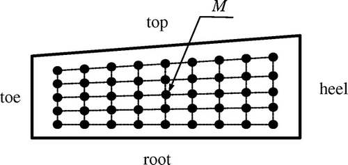
The input for DTCA is the tooth surface grids of spiral bevel gears. These grids are formed by CMM with 5 points along tooth profile and 9 points along tooth width. Figure shows the layout of the grids in the projection plane that is related to the grids on tooth surfaces as(1)
(1)
where X, R are the coordinates of the node of the grids on the projection plane; xo, yo and zo are the three components of the position vector ro indicating the node of the tooth surface grids.
Since the grids are based on the real tooth surfaces, they are defined as the OTSG which are limited within the tooth surface boundary. As OTSG’s are smaller than the tooth surfaces, only part of the meshing performances is to be emerged.
2.2. Discrete tooth contact analysis (DTCA)
DTCA is performed as follows:
The OTSG of the pinion and gear, with the pinion tooth top facing the gear tooth root, are placed as the required intersection angle in a meshing coordinate system Sm which is rigidly connected to the housing. To find the initial contact point, the pinion OTSG is kept stationary, while the gear OTSG is rotated about its axis of rotation to contact the pinion OTSG at a point by applying the tooth surface scanning method.[Citation9,28] The contacted point usually is not coincided with the node of the grids exactly. Its approximate position is calculated by third-order bi-spline interpolation and projected to the projection plane. The instant contact area, which is nearly an ellipse, can also be found with the tooth surface scanning method when the elastic approach is assumed to be 0.00635 mm at the point.
The pinion OTSG is rotated in a constant increment clockwise and counter clockwise, respectively, and the gear OTSG is rotated accordingly to contact with the pinion OTSG until the meshing point exceeds the boundary of OTSG of the pinion or gear.
The above process results in discrete contact points and corresponding transmission errors which provide the data for further manipulation.
2.3. Meshing performances at the mean contact point
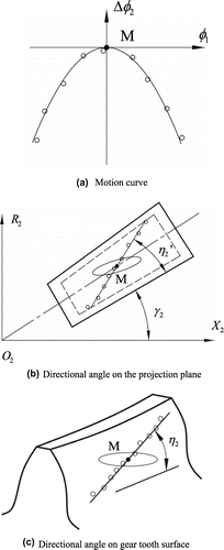
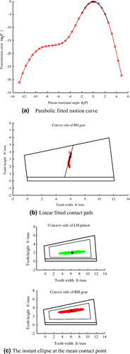
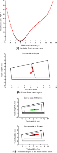
The discrete transmission error points are fitted by a parabola with second derivative . The top point M (Figure (a)) on the parabola can be treated as the mean contact point. Thus, the mean contact point position denoted by XM2 and RM2 on the projection plane of the gear and its tooth surface (Figure (b)) is roughly identified. The major axis of the contact ellipse at the mean contact point denoted by aM is calculated by taking the mean value of those of the two adjacent contact ellipses just in front of and behind the mean contact point. The contact path is fitted by linear regression. This yields the directional angle
on the gear projection plane which is different from the corresponding directional angle η2 on gear tooth surface. Since local synthesis [Citation29] requires η2 as one of its input, a conversion from
to η2 must be made.[Citation30]
3. Model for reconstruction of pinion tooth surface
3.1. Computational tooth surface grids (CTSG)
No matter the gear tooth surfaces are formatted or generated, the pinion tooth surfaces are generated, both for the concave and convex sides. The pinion tooth surfaces are the function of the head cutter and the machine-tool settings in addition to the relative motion between the head cutter and the work piece which are collectively called manufacturing parameters. Usually head cutters with straight blades are used. Machine-tool settings are calculated by local synthesis with or without modified roll motion. Obviously, reconstruction of the pinion tooth surfaces is equal to the determination of manufacturing parameters. In order to find the manufacturing parameters of the real tooth surfaces of the pinion, CTSG are introduced with its node position on the projection plane corresponding to OTSG as follows:(2)
(2)
where xc, yc and zc are the three components of the position vector rc on pinion tooth surfaces expressed by manufacturing parameters.
3.2. Reversing objective
Rotating CTSG with its centre node coincided with that of OTSG, pinion tooth surface deviation between them is formed. Here, the centre node is usually not coincided with the mean contact point. Reversing objective is set up by summation of the deviations of all nodes for CTSG and OTSG:(3)
(3)
where represents the position vector of the rotated CTSG and x is the vector of design variables.
3.3. Design variables
The machine-tool settings are calculated by local synthesis conditioned by the meshing performances at the mean contact point which are not precise since they are filtered from the DTCA and wait to be furnished in tooth surface reversing process. Furthermore, local synthesis only controls the meshing performances at and in the neighbourhood of the mean contact point, and the conventional modified roll motion is sometimes used to control the tooth surface other than the mean contact point. Current technology [Citation8] on numerical control machine provides various corrections of machine-tool settings to control the meshing performances over whole tooth surface. Here we chose blank offset correction, one of the corrections of the machine-tool settings, as a supplement approach to control the tooth surface of pinion. The blank offset correction is formulated as:(4)
(4)
where Ev1 is the blank offset at the mean contact point; Ci (i = 1, 2, … , 6) is the higher order coefficients and cr1 is the rotational angle of the cradle in the generation of the pinion tooth surface.
Based on the above analysis, we conclude that the vector of the design variables includes the following components expressed as:(5)
(5)
where (XM2, RM2) are the coordinates of the mean contact point on the projection plane; aM is the half major axis of the ellipse at the mean contact point; η2 is the directional angle of the contact path at the mean contact point; is the second derivative of the transmission error curve at the mean contact point and Ci (i = 1, 2, … , 6) is the higher order coefficient of blank offset variation.
Regulating the values of the design variables to minimize the reversing objective, CTSG is expected to approach to OTSG at and in the neighbourhood of the mean contact point, as well as over the whole tooth surface.
4. Numerical example
A zerol bevel gear drive in the accessory gear box of a helicopter engine, belonging to spiral bevel gear drives, is used to demonstrate the feasibility of the proposed methodology.
4.1. DTCA results
The basic parameters of the zerol bevel gear drive are shown in Table . Blank data of the pinion are calculated and shown in Table .
Table 1. Basic blank parameters.
Table 2. Blank data of the pinion.
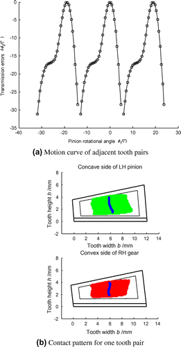
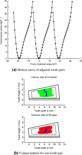
DTCA based on CTSG results in the function of transmission errors and the tooth contact pattern for the pinion concave and convex sides as shown in Figures and , respectively. The small circle ‘○’ on the dotted line in Figure (a) represents the discrete meshing position. The three adjacent motion curves do not intersect with other. This does not imply that tooth impact may occur during tooth pair change but means that the size of CTSG (in dash line in Figure (b)) is smaller than the nominal tooth surface (in solid line in Figure (b)). So, CTSG is unable to provide full meshing behaviour for one tooth pair. The symbols in Figure are analogy to Figure .
In order to get the meshing information at the mean contact point, data manipulation is conducted as shown in Figures and for pinion concave and convex sides, respectively. The motion curve in Figure (a) is fitted by a parabola in solid line with several discrete points close to the peak to highlight the meshing behaviour in the neighbourhood of the peak. Similar treatment is performed on the motion curve for the convex side as shown in Figure (a) but close to the valley and its neighbourhood. The symbol ‘●’ on the fitted parabola is the highest point, and the corresponding point on the linear fitted contact path is also denoted by symbol ‘●’ and is taken as the mean contact point as shown in Figures (b) and (b). The magnitude of the major axis of the instant ellipse at the mean contact point is taken as the average value of those of the instant ellipses just before and after the mean contact point as shown in Figures (c) and (c). The manipulated meshing information is listed in Table .
Table 3. Meshing performances.
4.2. Conversion from 
 to η2, initial machine-tool settings and higher order coefficients
Local synthesis requires η2 as one of its input other than . Thus, conversion from
to η2 is conducted.[Citation30] The results for the concave and convex sides of the pinion are shown in Figures and , respectively. The red circles are the results of TCA, while the solid line represents the directional angle of DTCA. With the given directional angle at the mean contact point on the projection plane together with other meshing information obtained from DTCA, calculation of initial machine-tool settings are carried out without modified roll motion as listed in Table , in which the value of η2 ensures
on the projection plane. The initial values of the higher order coefficients for blank offset are taken as zeros.
Table 4. Initial values of machine-tool settings.
4.3. Reconstruction of pinion tooth surfaces
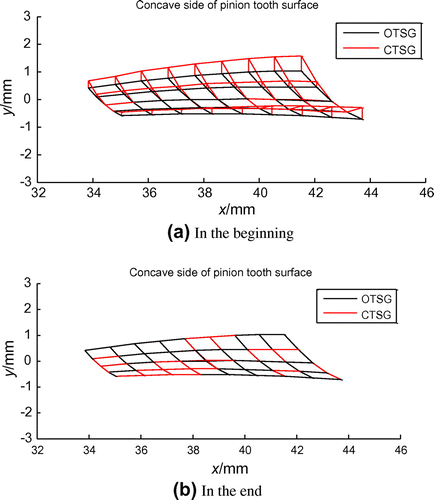
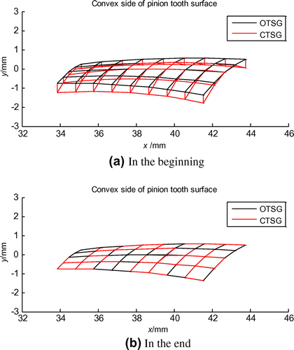
Using the unconstrained optimization function of MATLAB, the pinion concave and convex sides are reversed departing from the initial design variables as shown in Figures and , respectively, in which the solid line represents OTSG, while the dashed line represents CTSG. In order to show the tooth surface difference between OTSG and CTSG clearly, the deviations are enlarged by 10 times. From Figures and we can see that the CTSG approaches to OTSG gradually as the design variables are regulated automatically.
To evaluate the reversing calculation quantitatively, convergent deviations for all nodes are listed in Tables –. These tables show that many of the deviations are less than 1 μm. Only one node’s deviation is 3.4 μm or so. Even this is quite satisfactory for actual engineering.
Table 5. Tooth surface deviation of pinion concave side in the beginning (mm).
Table 6. Tooth surface deviation of pinion concave side in the end (mm).
Table 7. Tooth surface deviation of pinion convex side in the beginning (mm).
Table 8. Tooth surface deviation of pinion convex side in the end (mm).
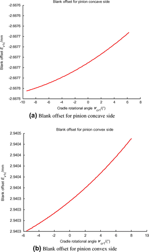
Figure is the correction of blank offset with respect to the cradle angle in pinion tooth surface generation for the concave and convex sides, respectively. By combining the local synthesis and non-linear correction of blank offset, the tooth surface deviations are eliminated over whole tooth surface.
The reversed meshing performances are listed in Table . The corresponding machine-tool settings are listed in Table .
Table 9. Reversed meshing performances.
Table 10. Reversed machine-tool settings.
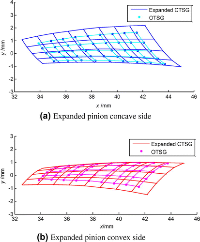
Based on the reversed manufacturing parameter of the pinion, the tooth surfaces of the pinion are expanded from OTSG or reversed CTSG as shown in Figure , in which the solid line indicates the expanded CTSG, and the spotted line indicates the OTSG. Therefore, the real tooth surfaces of pinion are reconstructed successfully.
5. Conclusions
Local synthesis with blank offset correction is used to reverse the real tooth surfaces of face-milled spiral bevel pinion based on the CMM tooth surface grids.
DTCA and tooth surface scanning method are applied to provide the approximate meshing information at the mean contact point together with some data manipulation to filter the meshing behaviour at the mean contact point. This ensures the convergence of reversing objective.
The numerical example demonstrates the validity and feasibility of the proposed reversing techniques. The reconstructed tooth surfaces provide the necessary condition for real tooth contact analysis and prospect for current evaluation and further improvement.
Acknowledgements
We would like to thank AVIC Aviation Powerplant Research Institute for providing the opportunity in the corporation research of reverse engineering of spiral bevel pinions and gears.
References
- Litvin FL, Zhang Y. Local synthesis and tooth contact analysis of face-milled spiral bevel gears. NASA CR-4342, AVSCOM TR-90-C-028, NASA Office of Management Scientific and Technical Information Division; 1991.
- Stadtfeld HJ, Gaiser U. The ultimate motion graph. ASME J. Mech. Des. 2000;122:317–322.10.1115/1.1286124
- Argyris J, Fuentes A, Litvin FL. Computerized integrated approach for design and stress analysis of spiral bevel gears. Comput. Methods Appl. Mech. Eng. 2002;191:1057–1095.10.1016/S0045-7825(01)00316-4
- Litvin FL, Alfonso F, Mullins BR, Woods R. Computerized design, generation, simulation of meshing and contact, and stress analysis of formate cut spiral bevel gear drives. NASA/CR-2001-210894, ARL-CR-467, National Technical Information Service; 2003.
- Alfonso F, Gonzalez-Perez I, Litvin FL, Hayasaka K, Yukishima K. Design, manufacture, and evaluation of low-noise high-endurance spiral bevel gear drives. Paper presented at: Power Transmission and Gearing Conference; 2005 Sep 24–28; Long Beach, CA.
- Litvin FL, Alfonso F, Hayasaka K. Design, manufacture, stress analysis, and experimental tests of low noise and high endurance of spiral bevel gears. Comput. Methods Appl. Mech. Eng. 2006;41:83–118.
- Wang PY, Fong ZH. Fourth-order kinematic synthesis for face-milling spiral bevel gears with modified radial motion (MRM) correction. ASME J. Mech. Des. 2006;128:457–467.10.1115/1.2168466
- Fan Q. Enhanced algorithms of contact simulation for hypoid gear drives produced by face-milling and face-hobbing processes. ASME J. Mech. Des. 2007;129:31–37.10.1115/1.2359475
- Sheveleva GI, Volkov AE, Medvedev VI. Algorithms for analysis of meshing and contact of spiral bevel gears. J. Mech. Mach. Theory. 2007;42:198–215.10.1016/j.mechmachtheory.2006.02.009
- Simon V. Computer simulation of tooth contact analysis of mismatched spiral bevel gears. J. Mech. Mach. Theory. 2007;42:365–381.10.1016/j.mechmachtheory.2006.02.010
- Simon V. Influence of tooth errors and misalignments on tooth contact in spiral bevel gears. J. Mech. Mach. Theory. 2008;43:1253–1267.10.1016/j.mechmachtheory.2007.10.012
- Tsai YC, Hsu WY. The study on the design of spiral bevel gear sets with circular-arc contact paths and tooth profiles. J. Mech. Mach. Theory. 2008;43:1158–1174.10.1016/j.mechmachtheory.2007.08.004
- Teixeira Alves J, Guingand M, de Vaujany J-P. Set of functions for the calculation of bending displacements for spiral bevel gear teeth. J. Mech. Mach. Theory. 2010;45:349–363.10.1016/j.mechmachtheory.2009.09.006
- Mermoz E, Astoul J, Sartor M, Linares JM, Bernard A. A new methodology to optimize spiral bevel gear topography. CIRP Ann. Manuf. Technol. 2013;62:119–122.
- Litvin FL, Zhang Y, Kieffer J, Handschuh RF. Identification and minimization of deviations of real gear tooth surfaces. ASME J. Mech. Des. 1991;113:55–62.10.1115/1.2912751
- Litvin FL, Kuan C, Wang JC, Handschuh RF, Masseth J, Maruyama N. Minimization of deviations of gear real tooth surfaces determined by coordinate measurements. ASME J. Mech. Des. 1993;115:995–1001.10.1115/1.2919298
- Stadfeld HJ. Handbook of bevel and hypoid gears. New York (NY): Rochester of Institute of Technology; 1993.
- Wang J. A study on the tooth surface geometrical precision control of spiral bevel and hypoid gears based on 3-D coordinate measuring [dissertation]. Xi’an: Xi’an Jiaotong University; 2003 ( in Chinese).
- Wang XC, Wang J, Jiang H, Li RF, Feng WJ. Tooth surface measurement and machine-settings correction of spiral bevel gear. Chin. J. Mech. Eng. 2003;39:125–128 ( in Chinese).
- Wang ZY, Zeng T. Correction of tooth flank errors of spiral bevel gear based on proportional change parameters. Chin. J. Mech. Eng. 2010;46:43–47 ( in Chinese).10.3901/JME.2010.01.043
- Artoni A, Gabiccini M, Kolivand M. Ease-off based compensation of tooth surface deviations for spiral bevel and hypoid gears: only the pinion needs corrections. J. Mech. Mach. Theory. 2013;61:84–101.10.1016/j.mechmachtheory.2012.10.005
- Simon V. Optimal machine tool setting for hypoid gears improving load distribution. ASME J. Mech. Des. 2000;123:577–582.10.1115/1.1414129
- Fuentes A, Gonzalez-Perez I, Litvin FL, Hayasaka K, Yukishima K. Determination of basic machine-tool settings for generation of spiral bevel gears from blank data. Paper presented at: 10th Power Transmission and Gearing Conference; 2007 Sep 4–7; Las Vegas, NV.
- Cao XM, Fang ZD, Xu H, Su JZ. Design of pinion machine-tool settings for spiral bevel gears by controlling contact path and transmission errors. Chin. J. Aeronaut. 2008;21:179–186.
- Liu GL, Shen YW, Wang SM. Determination of contact path of spiral bevel gears by rigid support. Mech. Sci. Technol. 2001;20:392–394 ( in Chinese).
- Su ZJ, Wu XT, Mao SM, Li JG. Design of hypoid gear tooth surface represented by non-uniform rational B-spline polynomial. J. Xi’an Jiaotong Univ. 2005;39:17–20 ( in Chinese).
- Wang XL, Wang YZ, Rao F, Zhong YF. Study on parametric tooth surface of hypoid bevel gears. Mech. Transm. 2005;29:23–26 ( in Chinese).
- Wang PY, Fong ZH. Adjustability improvement of face-milling spiral bevel gears by modified radial motion (MRM) method. J. Mech. Mach. Theory. 2008;43:1253–1267.
- Litvin FL. Gear geometry and applied theory. Englewood Cliffs (NJ): PTR Prentice Hall; 1994. Chapter 6–8; p. 107–281.
- Liu GL, Tian YJ, Jiang P. Realization of expected direction angle of SGM spiral bevel gears based on local synthesis. Paper presented at: 2010 International Conference on Engineering Design and Optimization (ICEDO 2010); 2010 Oct 28–30; Ningbo, China.

