 ?Mathematical formulae have been encoded as MathML and are displayed in this HTML version using MathJax in order to improve their display. Uncheck the box to turn MathJax off. This feature requires Javascript. Click on a formula to zoom.
Abstract
An inverse geometry problem of identifying simultaneously two irregular interfacial boundaries along with the mechanical properties of the interface domain located between the components of multiple (three) connected regions is investigated. A discrete number of displacement measurements obtained from a uniaxial tension test are used as extra information to solve this inverse problem. A unique combination of global and local optimization method is used, that is, the imperialist competitive algorithm (ICA) to find the best initial guesses of the unknown parameters to be used by the local optimization methods, that is, the conjugate gradient method (CGM) and the simplex method (SM). The CGM and SM are used in series. The performance of these local optimization methods is dependents on the initial guesses of the unknown boundaries and the mechanical properties, that is, Poisson’s ratio and Young’s modulus, so ICA provides the best initial guesses. The boundary elements method is employed to solve the direct two-dimensional (2D) elastostatics problem. A fitness function, which is the summation of squared differences between measured and computed displacements at identical locations on the exterior boundary, is minimized. Several example problems are solved and the accuracy of the obtained results is discussed. The influence of the value of the material properties of the subregions and the effect of measurement errors on the estimation process are also addressed.
Introduction
Inverse application of the boundary elements method (BEM) to identify internal flaws, cavities, cracks and inclusions inside solid bodies dates back to late 1980s.[Citation1–7] Similar methodology has also been used in the case of shape estimation problems, to identify the shape of cavities and inclusions inside solid bodies.[Citation8–16] Unknown parameters in inverse heat transfer problems include the estimation of the boundary condition,[Citation17,18] thermal properties,[Citation19–21] energy production [Citation22] and so on.
The first paper addressing the problem of Identifying irregular interfacial boundary configuration between two homogenous, isotropic bodies was published by Huang and Chao [Citation23]. In this study, the inverse steady-state heat conduction problem along with the conjugate gradient method (CGM) and the Levenberg–Marquardt algorithm were implemented to identify a single-interface boundary using boundary temperature measurements. This study is continued in order to identify simultaneously two interfacial boundaries in a multiple region domain using boundary temperature measurements.[Citation24]
An inverse 2D elastostatics problem along with the genetic algorithm (GA) and the CGM are used to identify a single irregular interfacial boundary.[Citation25]
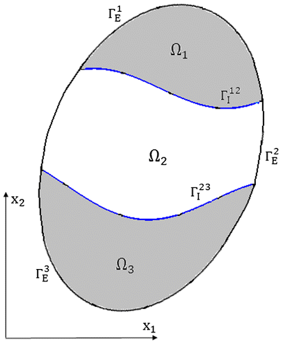
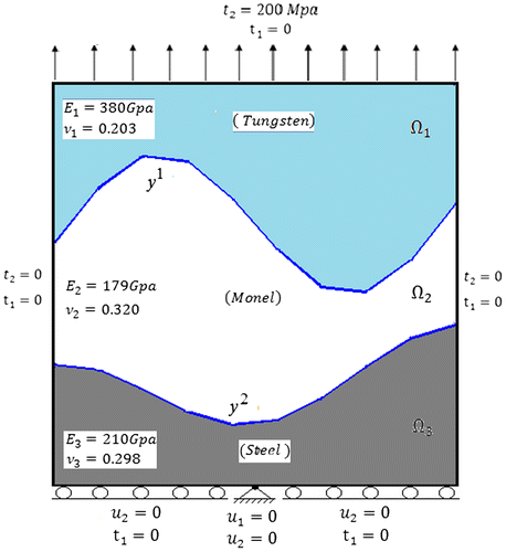
In this study, inverse application of the 2D elasto statics boundary elements problem is implemented to identify simultaneously two irregular interfacial boundaries along with the mechanical properties of the interface domain region (Ω2) as shown in Figure . Due to the success of this study, extension to the identification of multiirregular interfacial boundaries could be proposed as future investigation. Correlation of the two unknown boundaries, that is, and
, makes this highly ill-posed inverse problem difficult to converge.
ICA in combination with CGM and SM was found to be just as effective as other global optimization methods such as the GA [Citation12–14] or particle swarm optimization (PSO).[Citation26] Since the GA and PSO have been investigated previously, the imperialist competitive algorithm (ICA), which is more recent and very user-friendly, is used in this study.
Another advantage of this proposed inverse process is that there is no need to use any regularization method. With good initial guesses obtained by ICA, the CGM and the simplex method (SM) converge smoothly.
In this work, first, the governing differential equations for solving the direct 2D elastostatics problem by the BEM is considered, and then, the global and local optimization methods used in this study are introduced. Several example problems are solved, and the accuracy of the obtained results is discussed.
Direct problem
A linear elastic solid of uniform thickness h, loaded in some manner, is considered.
The equations of equilibrium in terms of displacements for an elastic solid body are as follows:(1)
(1)
where c11, c12, c22 and c33 are material constants. The boundary conditions are as follows:(2)
(2)
For and
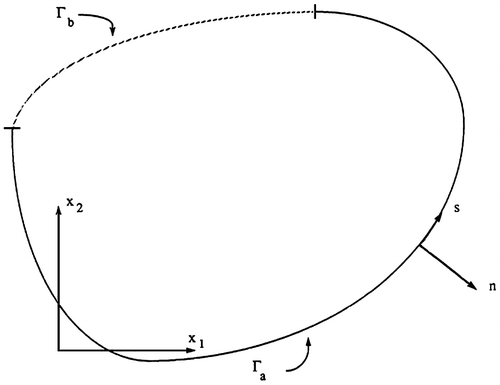
where ui is the component of displacement in the i direction, ti is the component of traction in the i direction, n1 and n2 are components of the outward-directed unit normal to the boundary Γ, s is a coordinate along the boundary, as shown in Figure , and fi(s) and gi(s) are prescribed functions.
The BEM used to determine the displacement at any point xi in Ω as shown in Figure can be determined from [Citation26] as follows:(3)
(3)
where, and
with summation on k. This equation is called the ‘filed equation’. U11 and U21 are the displacements and T11, and T21 are the tractions at point x in the infinite plane caused by an unit force in the x1 direction applied at point x. Similarly,
and
are the displacements and tractions at point x due to a unit force in the x2 direction, that is, the fundamental singular solution. uk, and
are the known displacements and tractions everywhere on Γ.
The boundary integral equation [Citation27] is used to find unknown boundary displacements, that is(4)
(4)
where and
if the boundary is smooth at xi, and
is the kronecker delta.
After the boundary discretization into linear elements, then Equation (Equation4(4)
(4) ) could be written in matrix form as follows:
(5)
(5)
The matrix is 2 N × 2 N and
is 2 N × 4 N where, N is the number of nodes on the discretized boundary.
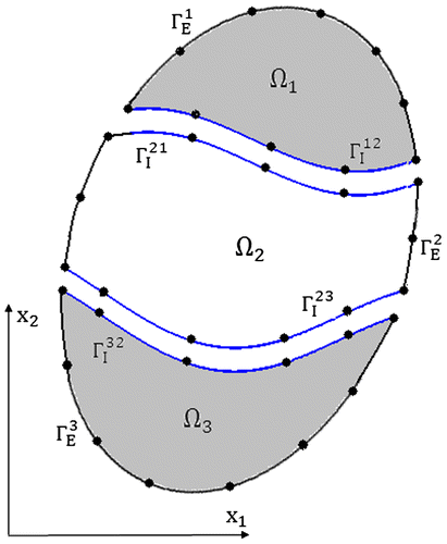
For the inhomogeneous body shown in Figure , the domain Ω is divided into three subdomains Ω1, Ω2 and Ω3, each having its own Poisson’s ratio and Young’s modulus. If Equation (Equation5(5)
(5) ) is applied to each subdomain, then for three subdomains:
where are tractions and displacements on
; …,
are tractions and displacements on
which is the boundary between material Ω1 and material Ω2;
are tractions and displacements on
;
are tractions and displacements on
;
are tractions and displacements on
;
are tractions and displacements on
and
are tractions and displacements on
, in x1 and x2 direction.
For each point i on and
the interface displacement conditions are:
(7)
(7)
And for tractions:(8)
(8)
Imposing the interface conditions on Equation (Equation6) gives:
(9)
(9)
In summary,(10)
(10)
the matrix is
and
is
where N1 is the number of nodes on exterior boundary of Ω1, N2 is the number of nodes on exterior boundary of Ω2, N3 is the number of nodes on exterior boundary of Ω3, N4 is the number of nodes on interface boundary
, and N5 is the number of nodes on the interface boundary
.
Equation (Equation10(10)
(10) ) is reordered based on known outer boundary conditions and then solved for the values of unknown displacements and tractions at the outer boundary nodes as well as all displacements and tractions at the interface boundary nodes
and
.
The inverse problem
In the previous section, the use of BEM to solve the direct 2D elastostatics problem for a multiply connected domain containing regions Ω1, Ω2and Ω3 was presented. In the direct problem, the governing differential equations, geometry, material properties and the boundary conditions are given and the unknown boundary data are calculated. In the inverse problem, some of the geometric features, such as the shape of the interfacial boundaries and/or material properties, are unknown, but some of the boundary data, that is, displacements or tractions can be measured and used as additional information to identify unknown parameters.
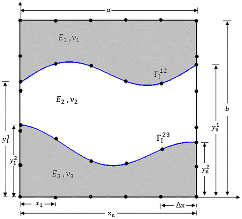
In this section, as shown in Figure , the shape and location of the interfacial boundaries and
, and mechanical properties, that is, Young’s modulus and Poisson’s ratio of the interface domain (Ω2) are unknown, but displacements measured on the left and right sides of the body under uniaxial tension are used as additional information.
The following column vectors are introduced:
: A column vector containing M measured boundary displacements, reflecting the true value of the unknown parameters.
: A column vector containing the same M boundary displacements computed by the BEM corresponding to the estimated value of the unknown parameters.
[Γ1]: A column vector containing n unknown parameters corresponding to the interfacial boundary.
[Γ2]: A column vector containing n unknown parameters corresponding to the interfacial boundary.
[Γ3]: A column vector containing 2 unknown parameters corresponding to the mechanical properties of the interface domain (Ω2).(11)
(11)
To keep the continuity of the interfacial boundary, only the y-component of the nodal locations on two interfacial boundaries are assumed unknown, and the distance in the x-direction between the two adjacent nodes are kept constant, as shown in Figure . Therefore, the unknown column vector [Γ] is defined as follows:(12)
(12)
This consists of 2n + 2 unknown parameters. The fitness function, which is the summation of squared differences between the measured displacements and calculated displacements at the same locations on the exterior left and right boundaries, is defined as follow:(13)
(13)
where ‘~’ denotes the estimated values of the unknown parameters.
Since convergence of local optimization methods, such as CGM, highly depends on very good initial guesses of the unknown parameters, ICA is first used to find the best suited possible values. The CGM uses the best initial guesses found, in order to start its process until convergence is reached. Finally, SM uses the results obtained from CGM as its best initial guesses to accurately identify the interfacial boundaries and mechanical properties of the interface domain. It will be shown in the example problems that the use of two local optimization methods in series reduces the error in converged results by about four percent.
Optimization methods
The global optimization method used in this study is the ICA. ICA is a novel global search heuristic inspired by sociopolitical competition. Like other evolutionary methods, ICA starts with an initial population. Population individuals called countries are divided into two types, namely colonies and imperialists, that together form empire. Some of the best countries in the population are selected to be the imperialists and the rest form the colonies of these imperialists. Imperialistic competition among these empires forms the basis of ICA. During this competition, weak empires collapse and powerful ones take possession of their colonies. Ideally, imperialistic competition converges to a state in which there is only one empire, and its colonies are in the same position and have the same cost as the imperialist. After dividing all colonies among imperialists and creating the initial empires, these colonies start moving toward their relevant imperialist country. The colony moves toward the imperialist by x units. In this movement, θ and x are random numbers with uniform distribution. Further information about ICA could be found in [Citation28].
The first local optimization method used in this study is the CGM. CGM is based on minimizing the fitness function, that is, Equation (Equation13(13)
(13) ). To minimize this function, the direction of descent pk(Γ) and the search step size βk in the following equation is needed [Citation29]:
(14)
(14)
where k = 1, … , iTerCGM and iTerCGM is the maximum number of iteration in the CGM. The direction of descent is given by(15)
(15)
where are gradient directions at iteration k. According to Polack-Ribiere,[Citation30] the conjugate coefficients γk are
(16)
(16)
where . In cases where algorithm does not converge after N step, γ gets the value of zero.
The gradient function is computed using the finite difference method.
(17)
(17)
To compute the search step size βk, using Equation (Equation14(14)
(14) ), the function
in step k + 1could be written as follows:
(18)
(18)
Using Taylor series, it is written in the form:(19)
(19)
where is computed by solving the direct problem using BEM. The search step size βk is determined by minimizing the function given by Equation (Equation14
(14)
(14) ) with respect to βk. The following expression results:
(20)
(20)
where needed to compute βk, is computed by solving direct problem with
.
The other local optimization method used is the SM. SM is an algorithm for solving the classical linear programming problem, developed by George B. Dantzig in 1947. Simplex is a simple nongradient optimization algorithm seeking the vector of parameters corresponding to the global extreme (maximum or minimum) of any n-dimensional function F(x1, x2, … , xn), searching through the parameter space.
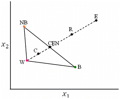
The two-dimensional simplex starts with three observations of the system response obtained with three different (x1, x2) parameter settings. These three observations correspond to the vertices of a triangle constituting the 1st simplex. In 3D space, four initial observations are required to define a tetrahedral body, and so on for the impossible to visualized spaces of higher dimensions.
From the evaluation of the response of each observation (RB: the response of the best point B, RNB: response of next best point NB, RW: response of worst point W), the position of the next point to be evaluated is indicated by reflection, expansion, or contraction operations as shown in Figure .
The iterations are terminated when no more significant improvement of the response is observed on moving from one simplex to another. It should be emphasized that when there are local extremes, it is highly probable that the algorithm to fail.[Citation31]
Problem set-up to obtain displacement measurements
To simulate the experimental measurements of displacement, a rectangular multiply connected domain of dimensions (1 m × 1 m) made up of Tungsten , Monel \
and Steel
\ with known boundary shape, under uniaxial tension as shown in Figure is solved by direct BEM for boundary displacements. The outer boundaries are divided into 64 linear elements and each interface boundary is divided into 14 elements.
The boundary displacement on the left and right sides of this model are computed and used as experimental results. Since the values of the fitness function or displacements at each iteration are not good indicators of convergence with knowledge of the actual shape of each interface boundary, in order to investigate the convergence process, an error coefficient is defined as follows:(21)
(21)
In this error coefficient, is the actual nodal location on each interface boundary, and
is the estimated location, and N is the number of locations. In this study, first, we solve the direct problem with known interfacial boundaries and known mechanical properties to compute the displacements on the exterior boundaries and then these computed displacements are used as the experimental measurements needed to solve the inverse problem.
Identification of the location and geometry of multi interfacial boundaries and mechanical properties of the interface domain
In order to solve the inverse problem and successfully estimate two interface boundaries simultaneously, some constraints need to be imposed:(22)
(22)
where N is the number of nodes on each interfacial boundary. These constraints are necessary since, at some stage of the estimation process, the two interface boundaries would interfere with one another or they might be found outside of the problem domain or interfere with the exterior boundaries.
The first task is to find the best initial guesses of the two interface boundaries and the mechanical properties of the interface domain. This information is needed for the local optimization methods, CGM and SM.
The initial guesses of interface boundaries are found by the ICA as straight lines drawn through the first and the last nodal locations located at some unknown vertical distance from the bottom. CGM uses these initial guesses in order to converge to the estimated shape of interface boundaries and mechanical properties of the interface domain. Iterations stop after the following criterion is satisfied.(23)
(23)
where Fn is the value of fitness function at iteration n and ɛ is taken to be a small number as 0.001.
Finally, the SM is employed in order to use the converged results found from CGM as its initial guesses to get a more accurate shape of the interface boundaries and mechanical properties of the interface domain.
Example problems
Three different examples are selected to show the ability of the proposed procedure to identify any shape of the interfacial configuration located anywhere in the domain. In all examples, the shape of the interfacial configuration is defined by a function. This allows us to investigate different locations and geometries and present the accuracy of the obtained results by computing the error coefficient, %error presented in Equation (Equation21(21)
(21) ).
In the first example, two different and continuous interfacial boundaries are selected as follows:(24)
(24)
The interface domain Ω2 is made up of Monel .
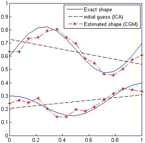
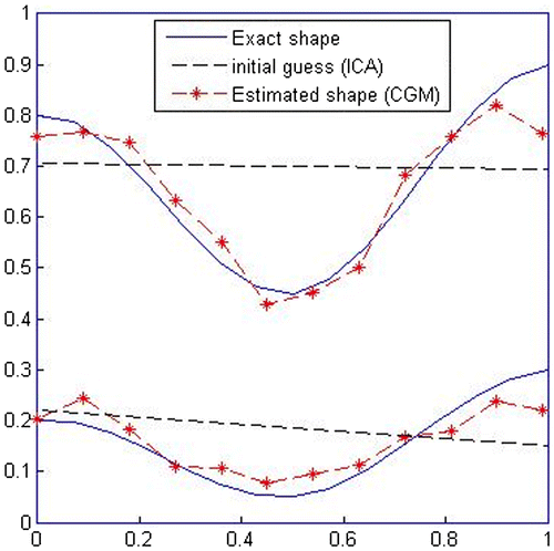
As shown in Figure , the initial guesses of interface boundaries are obtained by the ICA as two straight lines and the initial guesses of mechanical properties of interface domain are found as . Then, CGM uses these initial guesses to reach convergence. In this stage, the obtained results for mechanical properties of interface domain are
and the converged results have 8.97% error.
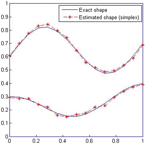
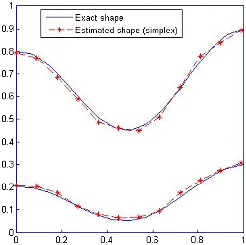
Finally, the SM is employed, which uses the interface boundaries and mechanical properties of the interface domain obtained by CGM, as its first guesses to identify a more accurate shape of the interface boundaries as shown by Figure , and the obtained results for the mechanical properties of interface domain are found as .
The result of this additional step in the estimation process is that, error is reduced to 2.2%, which indicates 6.77% improvement in final converged results. The accuracy of the identified interfacial boundaries is about 97.8%.
In the second example, the actual interfacial boundaries are defined as follows:(25)
(25)
In this example, one of the boundaries is assumed to be located close to the lower exterior boundary. The interface domain Ω2 is made up of Molybdenum .
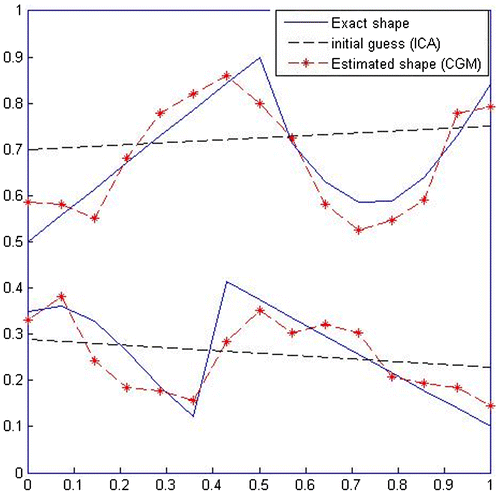
The initial guesses along with the identified shape of the interface boundaries from CGM are shown in Figure with the converged values of the mechanical properties as .
In this stage, the converged results have 9.9% error. As before, SM is employed to further estimate the interface boundaries and mechanical properties of the interface domain.
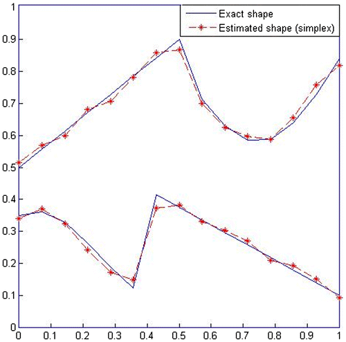
As shown in Figure , the two interface boundaries are identified with 95.75% accuracy with the converged values of the mechanical properties as . The improvement in accuracy is 4.65% as the result of using SM.
In the third example, the actual interface boundaries are defined as follows:(26)
(26)
The interface domain Ω2 is made up of Molybdenum .
As shown in Figures and , the two interface boundaries are identified with 94.55% accuracy with the converged values of the mechanical properties as . The improvement in accuracy is 5.045% as the result of using SM.
Investigating the effect of material properties at the three regions Ω1, Ω2and Ω3 on the identifying problem
To investigate the effect of material properties on the convergence of this inverse problem, three different combinations of materials introduced in Table are examined. It is observed that as the difference in material properties of the subdomains forming the multiply (three) connected domain decreases, even though convergence is achieved, the errors in converged results increase.
Table 1. The influences of material properties on estimation of the irregular boundary configurations.
The effect of experimental measurement errors on the estimation process
The next question investigated is the effect of inevitable experimental errors on the identification problem.
The erroneous experimental measurements are obtained by simulating the ‘experiment’ as follows.
The body is first analysed by the BEM using the actual shape of the interfacial boundaries and material properties.
Then, random errors are added to the computed boundary displacements, and these are taken to be the measured data. These errors are generated according to the following:(27)
(27)
Where η is the percent random number.
The unknown parameters are estimated using simulated experimental measurements with 1%, 2% and 3% errors. The results are shown in Figure . For errors up to 2%, even with an increase in error coefficient, the estimation process leads to acceptable shape of the interface boundaries, but after 2%, the estimation process lead to the wrong shape of interface boundaries.
Figure 13. Estimation of the interfacial boundaries using erroneous experimental measurements of displacement.
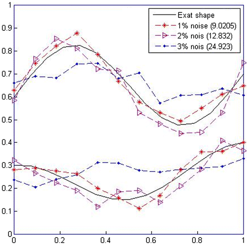
As shown in Figure for the case of 3% a random error in experimental measurements, the estimated shape of the interfacial boundaries is not acceptable and the inverse problem has converged to unrealistic results.
Conclusion
The inverse application of BEM to indentify simultaneously two unknown irregular interfacial boundaries and mechanical properties of the interface domain of an inhomogeneous body by utilizing surface displacement measurements and a unique combination of global (ICA), and local (CGM and SM) methods proves to be an effective optimizing procedure. Several cases involving different functional forms of interfacial boundary shape, different material properties and different measurement errors were considered, and from the examples presented, it is concluded that this combination of global and local optimization methods is very effective and reliable to identify any shape of interfacial configurations located anywhere within the problem domain.
Based on the results of this investigation, the following conclusions are drawn:
| • | The best initial guesses of the unknown interfacial boundaries could effectively be obtained by the ICA. | ||||
| • | Using CGM and SM in series proved to be highly effective in reducing the %error in converged results. | ||||
| • | SM converges reasonably fast to the accurate results when good initial guesses obtained by CGM are used. | ||||
| • | Convergence is achieved even with inevitable measurement errors up to 2%, but when experimental errors exceed 2%, the estimation procedure leads to an unrealistic shape of the interfacial boundaries. | ||||
| • | As the difference in material properties of the sub regions (Ω1, Ω2 and Ω3), decreases the %error coefficient in converged results also increases. | ||||
Disclosure statement
No potential conflict of interest was reported by the authors.
References
- Kennon SR, Dulikravich, GS. The inverse design of internally cooled turbine blades. ASME paper 84-GT-7. Presented at 29th International Gas Turbine Conference; 1984 June 4–7; Amsterdam.
- Murai T, Kagawa Y. Boundary element iterative techniques for determining the interface boundary between two Laplace domains: a basic study 3 of impedance plethysmography as an inverse problem. Int. J. Numer. Methods Eng. 1986; 35–47.10.1002/(ISSN)1097-0207
- Ohnaka K, Uosaki K. Simultaneous identification of the external input and parameters of diffusion type distributed parameter systems. Int. J. Control. 1987;46:889–895.10.1080/00207178708547401
- Dulicravich GS. Inverse design and active control concepts in strong unsteady heat conduction. Appl. Mech. Rev. 1988;41:270–277.10.1115/1.3151899
- Khodadad M, Altiero NJ. Characterization of the interior of an inhomogeneous body using surface temperature and/or heat flux measurements. Third Annual Inverse Problems in Engineering Seminar; 1989; East Lansing (MI).
- Gao Z, Mura T. On the inversion of residual stresses from surface displacements. J. Appl. Mech. 1989;56:508–513.10.1115/1.3176119
- Das S, Mitra AK. An algorithm for the solution of inverse Laplace problems and its application in flaw identification in materials. J. Comput. Phys. 1992;99:99–105.
- Khodadad-Saryazdi M. Characterization of the interior of an inhomogeneous body using surface measurements [Ph.D. thesis]. East Lancing (MI): Michigan State University; 1990.
- Kassab AJ, Moslehy FA, Daryapurkar AB. Nondestructive detection of cavities by an inverse elasto statics boundary elements method. Eng. Anal. Boundary Elem. 1994;13:4–555.
- Lee HS, Kim YH, Park CHJ, et al. A new spatial regularization scheme for the identification of the geometric shape of an inclusion in a finite body. Int. J. Numer. Methods Eng. 1999;46:973–992.10.1002/(ISSN)1097-0207
- Lee HS, Park CHJ, Park HW. Identification of geometric shapes and material properties of inclusions in two-dimensional finite bodies by boundary parameterization. Comput. Methods Appl. Mech. Eng. 2000;181:1–20.10.1016/S0045-7825(99)00165-6
- Khodadad M, Dashti-Ardakani M. Inclusion identification by inverse application of boundary element method, genetic algorithm and conjugate gradient method. Am. J. Appl. Sci. 2008;5:1158–1166.
- Khodadad M, Dashti-Ardakani M. Determination of the location, size and mechanical properties of an elastic inclusion using surface measurements. Inverse Prob. Sci. Eng. 2009;17:591–604.10.1080/17415970802309267
- Ardakani MD, Khodadad M. Shape estimation of a cavity by inverse application of the boundary elements 2D elasto statics problem. Int. J. Comput. Methods. 2013;10: 1350042.
- Ammari H, Beretta E, Francini E, et al. Reconstruction of small interface changes of an inclusion from modal measurements II: the elastic case. J. Math. Pures Appl. 2010;94:322–339.10.1016/j.matpur.2010.02.001
- Ammari H, Garnier J, Kang H, et al. Multistatic imaging of extended targets. SIAM J. Imaging Sci. 2012;5:564–600.10.1137/10080631X
- Alifanov OM. Solution of an inverse problem of heat conduction by iteration methods. J. Eng. Phys. 1972;26:682–689.
- Huang CH, Ozisik MN. Inverse problem of determining unknown wall heat flux in laminar flow through a parallel plate duct. Numer. Heat Transfer, Part A. 1999;21:55–70.
- Huang CH, Yan JY. An inverse problem in simultaneously measuring temperature-dependent thermal conductivity and heat capacity. Int. J. Heat Mass Transfer. 1995;38:3433–3441.10.1016/0017-9310(95)00059-I
- Tervola P. A method to determine the thermal conductivity from measured temperature profiles. Int. J. Heat Mass Transfer. 1989;32:1425–1430.10.1016/0017-9310(89)90066-5
- Huang CH, Ozisik MN. A direct integration approach for simultaneously estimating temperature-dependent thermal conductivity and heat capacity. Numer. Heat Transfer, Part A: Appl. 1991;20:95–110.10.1080/10407789108944811
- Huang CH, Yeh CY, Orland HRB. A nonlinear inverse problem in simultaneously estimating the heat and mass production rates for a chemically reacting fluid. Chem. Eng. Sci. 2003;58:3741–3752.10.1016/S0009-2509(03)00270-7
- Huang CH, Chao BH. An inverse geometry problem in identifying irregular boundary configurations. Int. J. Heat Mass Transfer. 1997;40:2045–2053.10.1016/S0017-9310(96)00280-3
- Huang CH, Shih CC. Identify the interfacial configurations in a multiple region domain problem. J. Thermophys. Heat Transfer. 2005;19:533–541.10.2514/1.11260
- Khodadad M, Ardakani MD. Application of the inverse elasticity problem to identify irregular interfacial configurations. Eng. Anal. Boundary Elem. 2009;33:872–879.
- Ardakani MD, Khodadad M. Identification of thermal conductivity and the shape of an inclusion using the boundary elements method and the particle swarm optimization algorithm. Inverse Prob. Sci. Eng. 2009;17:855–870.
- Brebbia CA, Dominguez J. Boundary elements: an introductory course. Southampton: Computational Mechanics Publications; 1989.
- Atashpaz-Gargari E, Lucas C. Imperialist competitive algorithm: an algorithm for optimization inspired by imperialistic competition. IEEE Congress on Evolutionary Computation; Singapore; 2007.
- Luenberger, DG. Linear and nonlinear programming. 2nd ed. Stanford, CA: Addison Wesley; 1989.
- Datta BN. Numerical linear algebra and application. Philadelphia: International Thomson; 1994.
- Constantinos E, Efstathiou R. Simplex method. Department of Chemistry National and Kapodistrian University of Athens; 2000. Available from http://www.chem.uoa.gr/applets/AppletSimplex/Appl_Simplex2.html

