 ?Mathematical formulae have been encoded as MathML and are displayed in this HTML version using MathJax in order to improve their display. Uncheck the box to turn MathJax off. This feature requires Javascript. Click on a formula to zoom.
ABSTRACT
An identification algorithm for the estimation of residual unbalances is developed for a flexible rotor-bearing system integrated with an active magnetic bearing (AMB). The main advantage of the present methodology is that it can be applied in situ and also with safe traversal of resonances during run-up. The flexible rotor-AMB system is modelled by the finite element method, considering randomly distributed residual unbalances along with disc discrete residual unbalances. In order to obtain equivalent discrete unbalances at limited disc locations for the balancing of the flexible rotor system, a generalized influence coefficient method (GICM) is proposed. Equivalent unbalances obtained at discrete balancing planes are used to check the reduction in unbalance responses. The proposed algorithm is compared with the conventional influence coefficient method (CICM) without AMB to check the accuracy and consistency of the estimated values of residual unbalances. The values estimated by both methods are found to be consistent, while the GICM has an advantage of using AMB for the safe operation of the unbalanced rotor at high speeds during measurements. In order to have a suitable discrete position of AMB (for effective estimation of residual unbalances), various rotor system models are considered with different positions of the AMB.
1. Introduction
Nowadays, in industries, the use of high-speed rotating machines has increased. So, there is a need for improving the characteristics and performance of such rotating systems. The problems that arise in these machines are the unbalances, misalignments, fatigue cracks, and wear and tear. The major problems are the residual unbalances, which cause excessive vibration in machines and lead to fatigue failures. The residual unbalances (inherent unbalances) in machineries occur due to manufacturing errors, improper commissioning, wear and tear, and so on. There is a need to actively control the rotor system vibration and it can be done effectively by the use of active magnetic bearing (AMB), which provides contactless actuation and helps in reduction of unnecessary vibrations during traversing of critical speeds or unstable regions [Citation1–3]. However, the design of AMB is complex as it involves the design of controllers, actuators, amplifiers, filters and sensors [Citation4–6]. AMB reduces excessive vibration by applying magnetic forces in opposite directions to unbalance forces. Nevertheless, instead of applying this corrective force all the time, if these corrective forces from AMBs can be used for finding the residual unbalance states of the rotor that will save unnecessary power consumption of AMBs, especially when rotors are still mounted on conventional bearings.
To reduce excessive vibration of rotors mounted on conventional bearings, many balancing methods have been developed by researchers, notably the conventional influence coefficient method (CICM) and modal balancing method [Citation1]. Kang et al. [Citation7] derived influence coefficient matrices from equations of motion for unsymmetrical rotors by using a complex coordinate representation and the finite element method (FEM). They predicted that the modified influence coefficients are found to be correlated to unbalance forces. Ehyaei et al. [Citation8] investigated a system of unbalanced flexible shaft equipped with ‘n’ automatic ball balancers. They concluded that if the auto ball balancers are closer to the unbalanced masses distributed in the shaft, a better vibration reduction is achieved. Lee et al. [Citation9] studied an electromagnetic type active balancing device and a balancing programme using the influence coefficient method for both simple and reliable structures. Sudhakar and Sekhar [Citation10] identified faults in the rotor system by minimizing the difference between equivalent loads estimated in the system. Pennacchi et al. [Citation11] balanced the rotor system using high breakdown point and bounded influence estimators.
Several of the research works have been done to determine the magnetic forces and stiffness parameters of AMBs. Autila et al. [Citation12] predicted the performance and parameters of a linearized model of radial magnetic bearings by using a nonlinear two-dimensional FEM. Tiwari and Chakravarthy [Citation13] estimated bearing dynamic parameters and residual unbalances simultaneously using impulse response measurements for a multi-degree-of-freedom flexible rotor system. Imlach et al. [Citation14] estimated force and stiffness of radial AMBs using the linear magnetic circuit theory. Zhou et al. [Citation15] obtained the stiffness and damping coefficients of an AMB by using the magnetic bearing as a sinusoidal exciter. Tiwari and Chougale [Citation16] developed an identification algorithm for estimating speed-dependent parameters of AMB using flexible rotors fully levitated on AMBs. They further validated their work with the experimental data.
Lots of researches have been carried out in the design of the AMB controller for the rotor system. Various control principles have been applied to the magnetic bearing from the traditional proportional-derivative controller to the contemporary advanced adaptive ones [Citation17–19]. Binder et al. [Citation20] were involved in the modelling, simulation, and control of AMB system by using the state-space formulation and PID controllers. Behzad et al. [Citation21] designed and implemented both linear and nonlinear control methods for a three-pole AMB. For a high-speed rotating system, the AMB can also be used to determine the balancing masses to physically balance the system as it reduces the controller effort and power consumed by the controlling system. In literature, the AMB has been used as the bearing support (for the static load of a rotor), controller (for dynamic internal disturbances) and exciter (for the system response independent dynamic external excitation), individually or in combinations. The literatures on the use of AMB for condition monitoring are rare. Conventionally, the AMB is used as an exciter to give a known excitation and based on the input and output information the system fault parameters are estimated. AMBs have also been utilized for fully levitating rotors for very high-speed applications but still, several applications require rotors supported mainly on conventional bearings. Especially for flexible rotor applications and balancing them in situ is still a great challenge since it requires measurements up to operating speed before balancing the rotors and herein the AMB as a controller can help in such dynamic balancing of flexible rotors.
In the present work, the AMB is used as a controller in a flexible rotor-bearing system and the controlling force and associated suppressed rotor responses are used to find the unbalance state of the rotor. The advantage of it is to suppress the vibration during measurement even at high speeds and then this suppression force along with responses are used to get the estimate of residual unbalances. Section 2 describes the rotor system and finite element formulation for the rotor-bearing-AMB system. Section 3 illustrates the formulation of CICM and proposed generalized influence coefficient method (GICM) for the balancing of flexible rotors. Section 4 describes the numerical simulation involved in the prediction of unbalances and balancing of the rotor system. Section 5 shows the estimation of unbalances with different rotor systems and selection of the appropriate position of AMB in the rotor system. Section 4 concludes the present work.
2. Rotor-bearing-AMB model descriptions
A flexible rotor-bearing system integrated with AMBs, as shown in Figure , has been considered for the study. It consists of rigid discs mounted on flexible shafts that are connected by couplings. The AMBs are used as controlling devices to prevent excessive vibrations at high speeds. Flexible shafts are supported on conventional bearings with cross-coupled stiffness and damping terms. AMBs have linearized cross-coupled displacement and current stiffnesses. In this rotor system, discs are assumed to be balancing planes and residual unbalances are estimated in these planes. A proportional–integral–derivative (PID) controller is used for AMBs.
2.1. Finite element formulation of the rotor-AMB system
In the FEM, the rotor system is discretized into smaller elements (Figure ) to simplify the formulation. Equations of motion of each element are considered separately and reassembled to get the global equations of motion of the complete assembly. Then boundary conditions are applied to the global equations to get the desired governing equations. In this model, unbalance forces (both shaft and disc unbalances), inertia forces, gyroscopic effect (discs only), AMB forces, and the stiffness and damping characteristics of conventional bearings are considered. Three orthogonal axes have been selected, i.e. z-axis along the shaft axis, x-axis and y-axes are perpendicular to the shaft axis. Shaft elements are having four degrees-of-freedom at each node (two transverse translational and two transverse rotational).
Equations of motion for the rotor system are given as
(1)
(1)
with
(2)
(2)
where ω is the spin speed of the rotor, M, C, G and K represent the mass, damping, gyroscopic and stiffness matrices, respectively [Citation2]. Details of the force vector, f, and the displacement vector, η, have been provided in the Appendix. The above equation is rearranged as follows, to obtain the displacement vector from the SIMULINK model.
(3)
(3)
The displacement and magnetic force vectors obtained from the SIMULINK software have been used in GICM that is explained next to obtain equivalent residual balance masses of the flexible rotor-bearing system.
3. Formulation of the conventional and GICMs
Two different types of technique are developed for the purpose of balancing of the flexible rotor system. The first one is modal balancing technique developed by Bishop and Gladwell [Citation23] and the second is influence coefficient method developed by Drechler [Citation24]. The CICM works well if the rotor is mounted on only conventional bearings. In the system having AMB, conventional methods cannot be used as the responses produced by trial masses may not directly reflect because of the AMB. In the present work, an AMB is used as controlling device, so in order to obtain the balance masses at disc locations for the balancing, the flexible rotor system a GICM has been proposed. The details of CICM and GICM have been discussed in next subsections.
3.1. Conventional influence coefficient method
The CICM is widely used approach for balancing of rotor systems in industrial applications. The balancing procedure is easy to carry out with the help of computer codes and requires very little knowledge of the rotating machineries and physical-mathematical modelling. The CICM is used to predict residual unbalances in a rigid as well as flexible rotor system with the use of displacement values at different measuring planes. Displacements values are obtained for different trial unbalances at balancing planes for estimation of influence coefficients. Then, these are used in obtaining residual unbalances at balancing planes.
In the CICM, n numbers of balancing planes are selected for trial unbalances and p numbers of measurement planes are considered for the measurement of displacements of the rotor system. Apart from this, a common reference signal is considered to have phases of all measured signals. The displacement vector, d(ω), and unbalance vector, w, are related with influence coefficient matrix, B(ω), for a particular rotor speed, as
(4)
(4)
With
and
where w1, w2, … , wn are residual unbalances at the n number of balancing planes and these are independent of the rotor speed. Rxpand Ryp are amplitudes of measured displacements in the x and y-axis directions, respectively; φxpand φyp are phase angles of the displacements in the x and y-axis directions, respectively, with respect to a fixed point of the shaft; and . The first column of influence coefficient matrix:
,
, … ,
and
are defined as the displacements at different measuring planes in x and y directions, respectively, per unit residual unbalance (w1). Similarly, other columns of B(ω) can be defined corresponding to different residual unbalances. The influence coefficients matrix, B(ω) can be obtained considering different trial unbalance in each balancing plane at a time and estimating displacements at various measuring planes as
(5)
(5)
with
where TR is the trial unbalance added at one of the measuring plane, and m1 is the trial mass, φ1 is corresponding phase and e1 is the eccentricity. The second subscript in displacements (x11, y11, … , xp1, yp1) represents corresponding to balancing plane in which trial unbalance is kept. It is assumed that the influence coefficient does not change by adding small trial unbalance. On subtracting Equation (4) from Equation (5), we get
(6)
(6)
which gives the first column of the influence coefficients as
(7)
(7)
Similarly, the second column of the influence coefficient matrix can be obtained by adding a trial unbalance on second balancing plane, and similarly other column influence coefficients can be obtained. For flexible rotors influence coefficients change with rotor speed. For different speeds in a particular run-up, above equations will take the form, as
(8)
(8)
with
where the superscript in ω represents a particular speed of the rotor. The vectors d(ω1), d(ω2), … , d(ωf) are the complex displacements corresponding to different speeds obtained from FFT of the time domain data (the procedure in discussed subsequently). The influence coefficients can be obtained for different speed by taking different trial unbalances as shown in Equations (4)–(6) for a single speed. Residual unbalances in the rotor system are obtained as
(9)
(9)
Now the extension of the CICM for the rotor-bearing-AMB system will be presented.
3.2. Generalized influence coefficient method
The GICM has been proposed to predict residual unbalances in a rotor-AMB system with the use of displacement values at various measuring planes and magnetic force values of AMBs, while rotors are still supported on conventional bearings. Displacements and magnetic forces are obtained for different trial unbalances at disc locations (considered as balancing planes) for the estimation of generalized influence coefficients. Then, these are used in obtaining residual balance masses at balancing planes. Equations involved in the formulation of GICM are described now.
Displacement vectors corresponding to p number of measuring planes and magnetic forces corresponding to q number of AMBs are used to obtain residual unbalances at n number of balancing planes. In fact, magnetic force vectors contain both displacement and current at AMB locations. The complex displacement vector taken at different measuring planes in the x- and y-axis directions is shown in Equation (4). The complex magnetic force vectors at AMB locations are represented as
(10)
(10)
The complex magnetic force vector, f(ω), the displacement vector, d(ω), and unbalance vector, w, are related with generalized influence coefficient matrix, G(ω), for a particular rotor speed, as
(11)
(11)
with
where w1, w2, … , wn are residual unbalances at the n number of balancing planes. Herein, it should be noted that now d(ω) is the displacement vector in presence of AMB in the rotor system. The generalized influence coefficients matrix, G(ω) can be obtained considering different trial unbalance in each balancing plane at a time and measuring corresponding displacements at various measuring planes, as
(12)
(12)
where TR is the trial unbalance added at one of the measuring planes as shown in Equation (5). Herein, the second subscript of displacements and magnetic forces represents the plane at which the trial mass was kept. On subtracting Equation (11) from Equation (12), we get
(13)
(13)
which gives,
(14)
(14)
(15)
(15)
Similarly, the second column of the generalized influence coefficient matrix can be obtained by adding trial unbalance on next balancing plane. For different speeds in a particular run-up, above equations will take the form, as
(16)
(16)
with
and
where, h(ω1), h(ω2), … , h(ωf) are the complex displacement and magnetic force vectors corresponding to different speeds obtained from FFT of the time domain data and magnetic force vectors. The generalized influence coefficient matrix G is obtained in a similar way as shown in Equations (12)–(15) considering different trial unbalances at the balancing planes. Residual unbalances in the rotor system are obtained as
(17)
(17)
The unbalances obtained in the previous equation are taken as balance masses with +180° phase and are added at the balancing planes to reduce the vibration of the rotor system.
4. Numerical simulations of balancing methodology
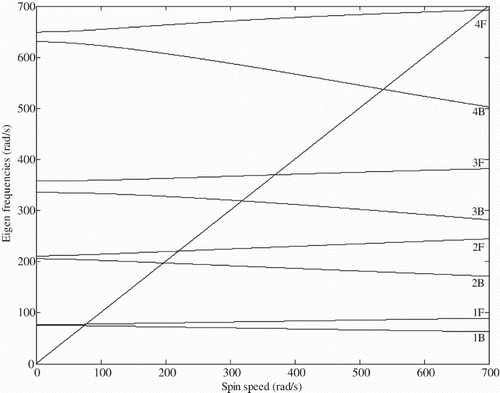
In the present study, the rotor system consists of three rigid discs (balancing planes), a flexible shaft, two conventional bearings (supports) and a magnetic bearing (controlling device) as shown in Figure (a). Initially, for the present rotor system (Model 1) the free vibration analysis has been done without considering AMB in the system to analyse the gyroscopic effect of the discs and predict the critical speeds of the rotor system. Equations of motion of the rotor system as given by Equation (1) are considered without any external forces for the free vibration analysis. Physical properties of the shaft, discs and conventional bearings [Citation22] have been taken as mentioned in Tables and . Eigen values are obtained for different values of the spin speed of the rotor system and Campbell diagram is plotted as shown in Figure . The plot shows that the rotor system crosses its fourth critical speed while rotating from 0 to 700 rad/s. It is also shown that a considerable split of natural whirl frequencies of the rotor system in presence of a gyroscopic effect in the range of operating speed. In each of splitting of natural whirl frequencies, the lower curve corresponds to the backward whirl and the upper curve corresponds to forward whirl in the plot. For the backward whirl, critical speeds obtained from Campbell diagram are 74.53, 197.48, 318.88, 537.19 rad/s and forward whirl are 77.49, 220.56, 369.85, 692.26 rad/s.
Table 1. Physical properties of the rotor (Model 1).
Table 2. Physical properties of conventional bearings.
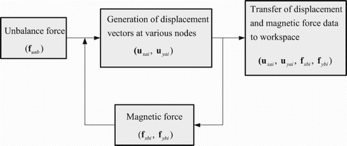
The proposed identification algorithm is tested with a flexible rotor system using a numerical simulation and detailed steps of it is illustrated with the help of the flowchart in Figure . The numerical rotor model is generated with the help of SIMULINK shown in Figure . The PID controller has following properties: KP = 4200 A/m, KD = 10 A-s/m and KI = 8000 A/m-s [Citation16]. In order to generate responses using the numerical simulation, properties of the conventional and magnetic bearings for all speeds are assumed and mentioned in Table and Table . The speed is varied from 5 to 700 rad/s with an angular acceleration of 139 rad/s2. The mass, stiffness and damping matrices, corresponding to Equation (1), are defined in MATLAB, which are then accessed by the SIMULINK model to generate unbalance forces (both of shaft and discs). Displacements and magnetic forces are then estimated in both orthogonal directions (x and y) at two conventional bearing locations and the AMB, respectively. In displacements and magnetic forces, 1% of noise (random values) has been added, to check the robustness of the algorithm against noise.
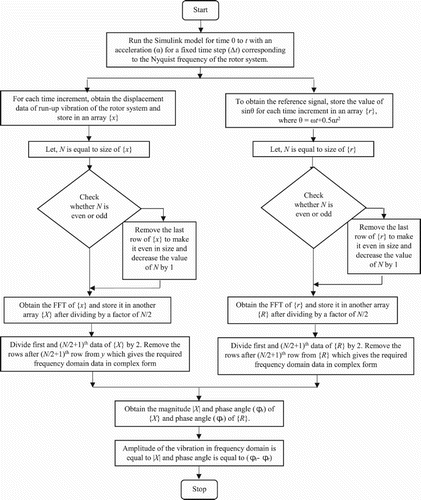
Figure 5. Flowchart of the flexible rotor balancing using generalized influence coefficients for the rotor-AMB system.
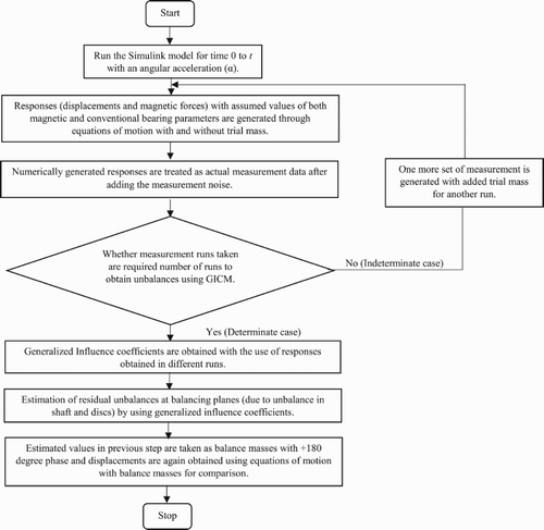
Table 3. Physical properties of AMB.
The time domain run-up displacement (or current) data obtained is made even in size in order to get the data for the half-spectrum. The half of the FFT data from the end has been removed (according to Nyquist criterion) and the rest has been used for obtaining unbalance masses using the GICM or the CICM. But before that, the phases of different run-up displacement (or current) data have to be corrected with respect to a common reference signal. As shown in Figure , fast Fourier transform (FFT) of both displacements and reference signal are carried out to obtain the complex displacement and reference signal vectors, respectively, with its amplitude and phase. The phase of the reference signal is subtracted from the phase of displacement (or current) signal to obtain the required phase of the displacement (or current) signal for different run-ups. The same process is carried out with the magnetic force vector obtained at AMB location to obtain complex magnetic force vectors in both x and y directions. The complex displacement and magnetic force vectors are obtained for the rotor system with and without trial unbalances at the balancing planes. With the help of displacements and magnetic forces (which otherwise can be easily measured in practice), residual unbalance mass magnitudes and phases are calculated for the flexible rotor system using GICM (through Equations (10)–(17)). The estimated residual unbalances at the balancing planes are considered as balance masses with 180° phase. Balance masses are then added to the rotor system and displacements at different rotor nodes are obtained in both time domain and frequency domain without considering AMB. Displacements are also obtained without balance masses and AMB to compare the reduction in unbalance responses with the addition of balance masses.
To check the algorithm, first only disc residual (discrete) unbalances are taken and with the help of displacements and magnetic forces, the unbalance masses magnitude and phase are calculated for the rotor system using the GICM (Equations (4)–(9)) as provided in Table . As shown in Table , the assumed and the estimated values of residual unbalances are found to be the same. Now, to check the reduction in unbalance responses, considering shaft residual (distributed) unbalances along with disc (discrete) unbalances, the magnitude and phase of equivalent unbalances at three balancing planes are obtained by the GICM as given in Table . The unbalances obtained have different values of magnitude and phase at the discs than mentioned in Table because of the introduction of the shaft unbalances in the system. Unbalance responses are again generated by adding estimated unbalances obtained as balance masses with 180° phase to the system. The displacement amplitude and phase values of responses have been obtained using algorithm mentioned in Figure in the horizontal direction, i.e. x-axis. The displacement amplitudes consist of only 1× harmonic at all speeds in the run-up condition of the rotor system. The displacement amplitude versus the rotor run-up speed plots have been plotted for the rotor system to check the reduction in unbalances after adding balance masses for rotor Model 1 at disc 1 and conventional bearing 1 positions and without using AMB as shown in Figures and . The peaks in Figure (b) show the amplitude of vibration while the rotor crosses its different critical speeds. As shown in these plots, unbalance responses are found to be reduced at different critical speeds after balancing in Figures (b) and (a). The variation of the phase lag (phase of the responses with respect to the reference signal) of the unbalance response with run-up speed is shown in Figures (d) and (b). The time domain plots before and after balancing for rotor Model 1 at disc 1 is shown in Figure (a,c), respectively. As shown in the plots, the amplitude of vibration has been reduced to the greater extent with the addition of the balance masses at the balancing planes.
Figure 8. (a) Displacement versus time curve without balancing, (b) displacement amplitude versus rotor run-up speed with and without balancing, (c) displacement versus time curve with balancing and (d) displacement phase versus rotor run-up speed (for Model 1 at disc 1, without magnetic bearing: magnetic force is considered only in the numerical simulation for obtaining unbalances.
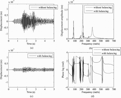
Figure 9. (a) Displacement amplitude versus rotor run-up speed with and without balancing and (b) displacement phase versus rotor run-up speed (for Model 1 at conventional bearing 1 without magnetic bearing: the magnetic force is considered only in numerical simulation for obtaining unbalances).
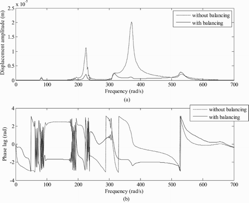
Table 4. Comparison of the assumed and estimated unbalance magnitudes and phases from the numerical simulation with residual unbalances only at discs and without unbalance in shaft for rotor Model 1 (with noise).
Table 5. Comparison of estimated unbalance magnitude and phase from GICM with residual unbalances in the shaft as well at discs for all three models shown in Figures , and .
4.1. Comparison of generalized and CICMs
In order to compare the suitability of the GICM and the CICM (while the AMB is not considered in rotor system) in the estimation of unbalances, by the latter method first displacements at two conventional bearing positions are taken and then additional displacements at AMB locations of the GICM (as such the AMB was absent in CICM) is also considered as shown in Table . The estimation of unbalances by using only displacements at conventional bearing positions are not appropriate as there is less reduction in unbalance responses after balancing (Figure ). The variation in estimated unbalances is because of using displacements at less number of locations. This may be due to on considering measurement at intermediate shaft locations, the modal information is captured more accurately. As provided in Table and Table , estimated unbalances by two methods (GICM and CICM) are nearly the same. The reduction in unbalance responses for the GICM has been shown in Figures , and for the CICM in Figures and in the frequency domain for Model 1 at disc 1 and conventional bearing 1.
Figure 10. (a) Displacement amplitude versus rotor run-up speed with and without balancing and (b) displacement phase versus rotor run-up speed (for Model 1 at disc 1 without magnetic bearing: magnetic force is not considered in numerical simulation for obtaining unbalance).
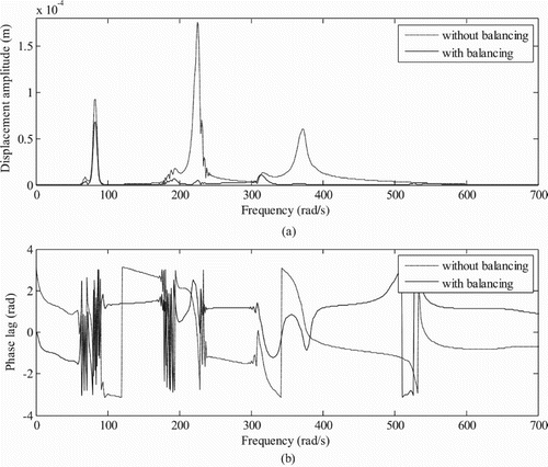
Figure 11. (a) Displacement amplitude versus rotor run-up speed with and without balancing and (b) displacement phase versus rotor run-up speed (for Model 1 at disc 1: displacement at the node position of magnetic bearing is taken without considering magnetic bearing in system by CICM).
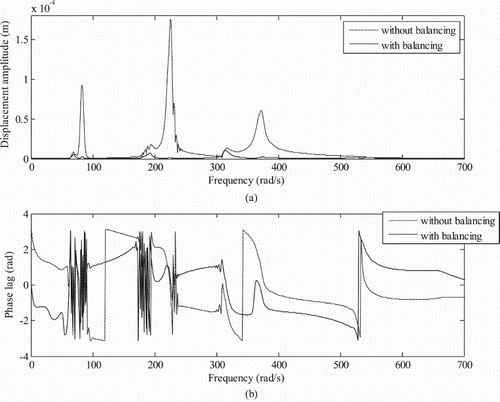
Figure 12. (a) Displacement amplitude versus rotor run-up speed with and without balancing and (b) displacement phase versus rotor run-up speed (for Model 1 at conventional bearing 1: displacement at the node position of magnetic bearing is taken without considering magnetic bearing in system by the CICM method).
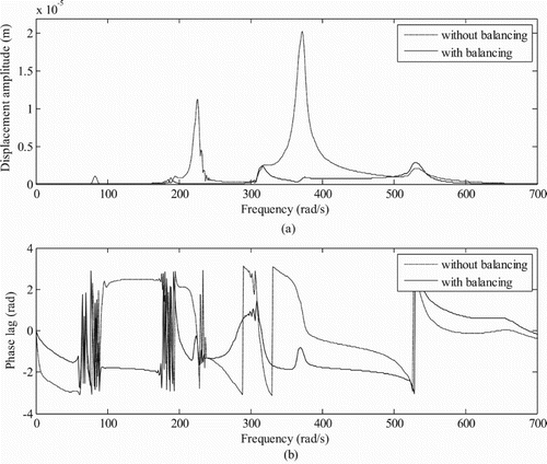
Table 6. Comparison of estimated unbalance magnitude and phase using CICM (without magnetic bearing).
However, it should be noted that as the balancing is required for the high-speed rotor system, so it would be difficult to run the rotor system supported on conventional bearings up to the operating speed for obtaining displacements. Conventional bearings may get damaged at high speeds while running without balancing for taking measurements. Moreover, measurements may not be reliable for the CICM, which also requires linearity assumption of the system. Herein, the use of AMB is advantageous in obtaining the reliable residual unbalances as it reduces the vibration to have linear system assumption valid. It also prevents the system from getting damaged at high-speed and ensures more reliable data.
Numerical simulation has been done initially for the rotor system with high acceleration (i.e. 139 rad/s2). In the same manner with low acceleration, i.e. at 34.75 rad/s2, the rotor system has been tested numerically. In both the cases, the estimated unbalance masses are found to be similar as shown in Table and Table .
Table 7. Comparison of estimated unbalance magnitude and phase from GICM with residual unbalances in the shaft as well at discs for Model 1 with low angular acceleration (i.e. 34.75 rad/s2).
5. Comparison of unbalance estimations with different rotor models
In order to determine the suitable position of AMB, apart from the rotor system in Figure , two different models have been selected having different position of the AMB as shown in Figure (Model 2) and Figure (Model 3). The GICM is then used to estimate the unbalances in these two models and estimates of unbalances are compared in Table .
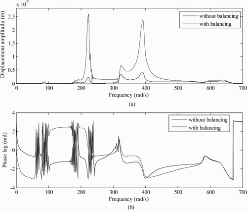
The amplitude of unbalance responses is lower for Model 2 than Model 1 and Model 3 as shown in Figure and Figures and , respectively. On the other hand, Model 3 shows the largest amplitude of unbalance response amongst the others. Variation of the displacement amplitude versus the rotor run-up speed have been plotted models at disc 1 and conventional bearing 1 positions for rotor systems to check the reduction in unbalances after adding correction masses for both rotors and without using AMB as shown in Figures –. As shown in these plots, unbalance responses are found to be reduced at different critical speeds after balancing as shown in Figures (a). The variation of the phase of the unbalance response is shown in Figures (b) and (b).
Figure 15. (a) Displacement amplitude versus rotor run-up speed with and without balancing and (b) displacement phase versus run-up speed (for Model 2 at disc 1 without magnetic bearing: magnetic force is considered in numerical simulation for estimating unbalances).
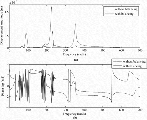
Figure 16. (a) Displacement amplitude versus rotor run-up speed with and without balancing and (b) displacement phase versus rotor run-up speed (for Model 3 at disc 1 without magnetic bearing: magnetic force is considered in numerical simulation for estimating unbalances).
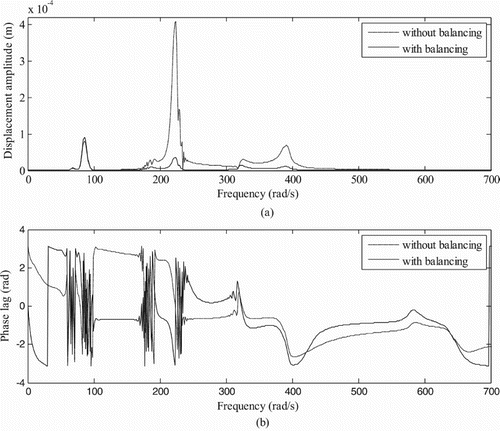
Figure 17. (a) Displacement amplitude versus rotor run-up speed with and without balancing and (b) displacement phase versus rotor run-up speed (for Model 2 at conventional bearing 1 without magnetic bearing: magnetic force is considered in numerical simulation).
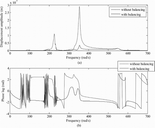
Figure 18. (a) Displacement amplitude versus rotor run-up speed with and without balancing and (b) displacement phase versus rotor run-up speed (for Model 3 at conventional bearing 1 without magnetic bearing: magnetic force is considered in numerical simulation).
The percentage deviation in residual unbalances estimation is also determined for 1% and 5% noise in responses as well as for ±1% and ±5% variation in Young’s modulus (E) and density (ρ). The percentage change in the magnitude and phase of residual unbalances is very low with the addition of noise and variation of physical properties of the rotor system as shown in Tables and .
Table 8. Percentage deviation in magnitude and phase of unbalances with variation in the noise level.
Table 9. Percentage deviation in magnitude and phase of unbalances with variation in Young’s modulus and density.
6. Conclusions
In the present work, an identification algorithm for the estimation of unbalances at selected balancing planes has been developed with the help of AMB as a controller in flexible rotor-bearing systems. Numerical responses obtained show that with the addition of correction masses there is an appreciable reduction in unbalance responses corresponding to different critical speeds. This shows that the present methodology predicts quite accurate values of magnitude and phase of unbalances that is present in the rotor system. The variation in estimated values of unbalances is found to be very low even in the presence of measurement noise and modelling errors. The above results also show that the use of GICM in the estimation of unbalances provides the nearly similar result as the CICM without AMB. However, the GICM also has the advantage of having AMB at high speed during measurement and subsequently while estimation than the CICM in which it is difficult to cross critical speeds without balancing a rotor for taking measurements. So, it is advantageous to use the GICM over conventional method for the rotor system at high speeds. The use of displacements at more number of locations in the estimation of unbalances gives more appropriate results. Among rotor models considered, the Model 2 is found to be more appropriate than other models (since it has much less reduction in unbalance responses after balancing). As we can see in Model 2, the position of AMB is approximately at the middle of the shaft between the conventional bearings, so the placement of the AMB is very much important. Application of the proposed methodology in a test rig or practical rotor would be very interesting. As a future work, physical trial masses can be replaced by ‘virtual unbalance’ through AMB, which would give similar force as of a ‘physical unbalance’. However, it needs multiple AMBs at each balancing planes that would pose practical difficulty.
Disclosure statement
No potential conflict of interest was reported by the authors.
References
- Tiwari R. Rotor systems: analysis and identification. Boca Rotan, FL: CRC Press, Taylor and Francis Group; 2017.
- Rao J. Rotor dynamics. New Delhi: New Age International; 1996.
- Childs DW. Turbomachinery rotordynamics: phenomena, modeling, and analysis. New York: Wiley; 1993.
- Bleuler H, Cole M, Keogh P, et al. Magnetic bearings: theory, design, and application to rotating machinery. Springer Science & Business Media; 2009.
- Chiba A, Fukao T, Ichikawa O, et al. Magnetic bearings and bearingless drives. Burlington: Elsevier; 2005.
- Mushi SE, Lin Z, Allaire PE. Design, construction, and modeling of a flexible rotor active magnetic bearing test rig. IEEE/ASME Trans Mechatron. 2012;17:1170–1182. doi: 10.1109/TMECH.2011.2160456
- Kang Y, Liu C-P, Sheen G-J. A modified influence coefficient method for balancing unsymmetrical rotor-bearing systems. J Sound Vib. 1996;194:199–218. doi: 10.1006/jsvi.1996.0353
- Ehyaei J, Moghaddam MM. Dynamic response and stability analysis of an unbalanced flexible rotating shaft equipped with n automatic ball-balancers. J Sound Vib. 2009;321:554–571. doi: 10.1016/j.jsv.2008.10.019
- Moon J-D, Kim B-S, Lee S-H. Development of the active balancing device for high-speed spindle system using influence coefficients. Int J Mach Tools Manuf. 2006;46:978–987. doi: 10.1016/j.ijmachtools.2005.07.048
- Sudhakar G, Sekhar A. Identification of unbalance in a rotor bearing system. J Sound Vib. 2011;330:2299–2313. doi: 10.1016/j.jsv.2010.11.028
- Pennacchi P, Chatterton S, Ricci R. Rotor balancing using high breakdown-point and bounded-influence estimators. Mech Syst Signal Process. 2010;24:860–872. doi: 10.1016/j.ymssp.2009.10.004
- Autila M, Lantto E, Arkkio A. Determination of forces and linearized parameters of radial active magnetic bearings by finite element technique. IEEE Trans Magn. 1998;34:684–694. doi: 10.1109/20.668066
- Tiwari R, Chakravarthy V. Simultaneous identification of residual unbalances and bearing dynamic parameters from impulse responses of rotor–bearing systems. Mech Syst Signal Process. 2006;20:1590–1614. doi: 10.1016/j.ymssp.2006.01.005
- Imlach J, Blair B, Allaire P. Measured and predicted force and stiffness characteristics of industrial magnetic bearings. J Tribol. 1991;113:784–788. doi: 10.1115/1.2920693
- Jin C, Xu Y, Zhou J, et al. Active magnetic bearings stiffness and damping identification from frequency characteristics of control system. Shock Vib. 2016;2016: Article ID 1067506, 8 pages.
- Tiwari R, Chougale A. Identification of bearing dynamic parameters and unbalance states in a flexible rotor system fully levitated on active magnetic bearings. Mechatronics (Oxf). 2014;24:274–286. doi: 10.1016/j.mechatronics.2014.02.010
- Mizuno T, Araki K, Bleuler H. Stability analysis of self-sensing magnetic bearing controllers. IEEE Transactions on Control Systems Technology. 1996;4:572–579. doi: 10.1109/87.531923
- Kim H-Y, Lee C-W. Design and control of active magnetic bearing system with Lorentz force-type axial actuator. Mechatronics (Oxf). 2006;16:13–20. doi: 10.1016/j.mechatronics.2005.09.005
- Chen K-Y, Tung P-C, Tsai M-T, et al. A self-tuning fuzzy PID-type controller design for unbalance compensation in an active magnetic bearing. Expert Syst Appl. 2009;36:8560–8570. doi: 10.1016/j.eswa.2008.10.055
- Sabirin CR, Binder A, Popa DD, et al. Modeling and digital control of an active magnetic bearing system. Romania Review of Technical Sciences Electrotechnical and Energy Series. 2007;52:157.
- Darbandi SM, Behzad M, Salarieh H, et al. Linear output feedback control of a three-pole magnetic bearing. IEEE/ASME Trans Mechatron. 2014;19:1323–1330. doi: 10.1109/TMECH.2013.2280594
- Bishop R, Gladwell G. The vibration and balancing of an unbalanced flexible rotor. J Mech Eng Sci. 1959;1:66–77. doi: 10.1243/JMES_JOUR_1959_001_010_02
- Drechsler J. Processing surplus information in computer aided balancing of large flexible rotors. In Proceedings of the Institution of Mechanical Engineers Conference on Vibrations in Rotating Machinery, Cambridge, UK; 1980. p. 65–70.
- Tiwari R. Conditioning of regression matrices for simultaneous estimation of the residual unbalance and bearing dynamic parameters. Mech Syst Signal Process. 2005;19:1082–1095. doi: 10.1016/j.ymssp.2004.09.005
Appendix
Rotor system matrices and vectors
Detailed matrices of equations of motion Equation (1) are given below.
Displacement vector corresponding to each element
(A1)
(A1)
where ηx and ηy are the displacement vectors for each element in x- and y-directions, respectively.
Magnetic force vector
(A2)
(A2)
with
where Ks is the displacement stiffness matrix, Ki is the current stiffness matrix, ηm is displacement vector at AMB and ic is the controlling current vector. Controller parameters kP represents the proportionality constant, kD represents the derivative constant and kI represents the integral constant. The dot and bar on the displacement represents differentiation and integration, respectively.
Unbalance force vector is given as
(A3)
(A3)
where
is the assembled unbalance force vector for discs and
is the assembled unbalance force vector for the shaft. Force vector for discs in x and y-direction is given as
(A4)
(A4)
where mi is the mass of unbalance, ei is the eccentricity, φi is the phase, and ω is the spin speed of the rotor.
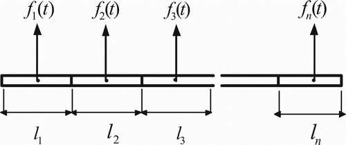
In order to introduce shaft unbalance in the rotor system, each element of the shaft has been divided into a finite number of segments (n), each segment is considered as discs with some random eccentricity and phase. The unbalance force acting on the element of the shaft is shown in Figure . The equation of unbalance force for each segment is written as
(A5)
(A5)
where ρ is the density of shaft, li is the length of each shaft segment, ei is the eccentricity for the segment and A is the area of cross section of the shaft. The choice of unbalances in each shaft segment is arbitrary. The subscript i = (1, 2, … , n). Net unbalance force in each element is given by
(A6)
(A6)
with
(A7)
(A7)
where fse is the net unbalance force in each element corresponding to four degrees-of-freedoms (DoFs) in each plane (x-z or y-z), δ is the Dirac delta function which enables the point force (shaft unbalance) as a distributed force description in form of integral, n(z) is the shape function for an 8-DOF shaft element subjected to transverse forces and z is the distance of the location of force from the right end of the element. Unbalance forces due to the shaft for each element are given as
(A8)
(A8)
and
(A9)
(A9)
where vectors fsxe and fsye are the unbalance forces due to the shaft in x and y-direction, respectively.


