
 ?Mathematical formulae have been encoded as MathML and are displayed in this HTML version using MathJax in order to improve their display. Uncheck the box to turn MathJax off. This feature requires Javascript. Click on a formula to zoom.
ABSTRACT
In this study, the development of a novel hydraulic robotic actuator is introduced. With the use of additive manufacturing (AM), lightweight and compact design can be achieved. A high load-to-weight ratio 3-DOF robot actuator with orthogonally connected hydraulic rotary cylinders is designed for AM. To validate the feasibility, a titanium hydraulic robot actuator is prototyped by using the metal powder bed fusion (M-PBF) AM process. A set of loading experiments are conducted on the AM-printed prototype. The study shows that system-level AM design and manufacturing methods can help gain increased output torque but with reduced weight and volume. With the use of hydraulic driving, the robotic actuator is more compact and solid to resist to tough environments as compared with the traditional actuators using electric motors. This study also implies the potential wide application of AM to design and print similar hydraulic link mechanism in heavy-duty robot or mobile humanoid robot.
1. Introduction
The applications of robots and robot manipulators are becoming increasingly extensive in various domains. Stipulations on the size, weight, flexibility, and resistance of robots have increased. With the development of newer processing techniques, materials, and innovative design methods, traditional industrial or humanoid robots can be redesigned to reduce weight, become compact, perform better, and be more flexible. In robots, actuators are key power elements which are usually electromechanical devices that generate electrical, magnetic, pneumatic, hydraulic, optical, or other forces to drive shafts or actuate controlled movements of equipment. Currently, there are three main types of actuators for robots, including electrical, hydraulic, and pneumatic types (Suzumori and Faudzi Citation2018). These actuators have different advantages and disadvantages respectively. The main advantages of electrical actuators are small size, ease of control, high control accuracy, and fast response. The advantages of hydraulic actuators include high-force density, high robustness to environmental impact, and ease of adding high-force degrees of freedom. But the weak points of hydraulic actuators are heavy and large in size, complex in control and relative expensive in manufacturing. While pneumatic actuators are relative cheap and easy for control. However, their disadvantages include imprecise control, low accuracy, and poor efficiency (Katz Citation2018; Zhang Citation2010). Among the three types of actuators, hydraulic actuators are widely used in high-DOF (degree-of-freedom) machines, where high-force DOFs can be added relatively easily using hydraulic actuators instead of electrical or pneumatic actuators. These applied hydraulic actuators are usually big in size and require much space for system installation. Hence, there are quite less cases for robots installed with hydraulic actuators, except some mobile robots or robot manipulators that need high power capability. For example, in the Istituto Italiano di Tecnologia, hydraulic rotary actuators were used in HyQ2Max for hip abduction and hip flexion, and a hydraulic cylinder was used for knee flexion (Semini et al. Citation2015). Hydraulic linear cylinders were used in the Bigdog project of Boston Dynamics Citationn.d..
However, constrained by the prevalent design and manufacturing methods, existing hydraulic actuators have limitations in terms of shape, volume, and weight. This cause problem to obtain a high load-to-weight ratio to gain efficiency in many robots and robot manipulators, especially for those mobile ones. In the traditional design, owing to the limitations of manufacturing on complex structure shapes and assembly interface constraints, lightweight bionic robot structure design solutions are usually hard to manufacture and cost much more than that with regular shapes since biomimetic structures are complex and have many freeform shapes, assembly interfaces and fine features. With the emergence of additive manufacturing (AM), efforts have been made to develop efficient solutions to address these challenges. Boston Dynamics has already applied AM to design and print lightweight and biomimetic structures to reduce the weight of robotic systems and improve their performance (Boston Dynamics Citationn.d.). Hydraulic piston cylinders have been embedded into printed structures to save more space and improve the driving performance as well as resistance under tough conditions such as jumping and running. These examples indicate that the combined use of AM and hydraulic driving may significantly improve the performance of heavy-duty or mobile humanoid robots. However, Boston Dynamics applied only piston cylinders to robotic legs. In fact, hydraulic rotary actuators are more compact to the hydraulic cylinders in many existing applications, e.g. construction machinery. Based on this, AM-printed rotary cylinders may have significant potential for the development of compact and lightweight robotic actuators, particularly in multiple-DOF systems. To prove this concept and meet the application needs of an engineering project, this study proposes a novel 3-DOF robotic actuator that uses three connected hydraulic rotary cylinders in an orthogonal arrangement to gain more space, reduce weight, and achieve larger output torque. To demonstrate the feasibility of the actuator, a printed prototype system is realised by employing a metal powder bed fusion (M-PBF) process using a titanium alloy. A set of performance tests was conducted on the printed prototype to verify the improved performance of the system. Specially, a new design for additive manufacturing method in the system-level was proposed for the prototype development at the first time. It can be adopted for the design of other system-level products in AM.
The remainder of this paper is structured as follows. In Section 2, the proposed hydraulic robotic actuator and its design and printing procedure are described. The kinematic and torque analyses of the novel system are presented in Section 3. The performance tests are described in Section 4, and a conclusion with future development perspectives is presented in Section 5.
2. Design and printing of hydraulic actuator
2.1. Design process and results
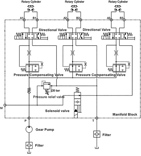
In this study, an engineering project requires a 7-DOF robot manipulator that can be used in a special oil container to execute some tasks. The manipulator should be high load-to-weight ratio and compact to save space for operation. In addition, for security reason, the robot manipulator should have less electric devices to reduce fire risk. To meet this need, hydraulic rotary actuators are adopted instead of electric motors. As the first prototyping step for the project, a tandem system of three hydraulic actuators with the same diameter was used to build a 3-DOF robotic actuator as the shoulder of the whole 7-DOF robot arm for concept proof. To realise 3-DOF, a hydraulic system is designed for driving and it is illustrated in . As depicted in the figure, theoretically, each of the joints in the actuator can rotate through more than 360°, that is, in a set of circles. However, the oil pipes, comprising soft material, may wind around each other to cause oil circulation problem if the joint rotates by more than 360°. Hence, in the prototype, a rotation of 270° for each joint was set as the objective of the demonstration, which can sufficiently meet the application requirements of the engineering project and it already performs better than several existing 3-DOF actuators. As the main design specification, the hydraulic pressure was set to 10 MPa to obtain enough power for task operation. The total volume was expected to fit within a bounding box of 200 mm × 200 mm × 400 mm to enable the operations in the narrow space of the special oil tank, and the final weight of the prototype was expected to be less than 6 kg to improve the load-to-weight ratio and match the performance of actuators using electric motors.
Figure 1. Hydraulic schematic of the actuator prototype.
Once the hydraulic system is determined, mechanical design in the system-level should be realised. As described in the literature, several design for AM methods have been proposed (Vaneker et al. Citation2020). However, these methods are only suitable for single-component design at the structural design level and they are rarely used for system design. Part consolidation design method for AM in the system-level is suitable for assembly design without or with less relative movement between components. For actuator design, where exist many relative movements, standard components and precision mechanisms, part consolidation method cannot solve the design problem in this paper. To tackle it, based on the prototype development experience, a new design for AM method in the system-level, named progressive system design method for AM is proposed. This method is based on the logic of system decomposition and component redesign, and it combines a set of design for AM methods as well as consider the interaction with non-AM/traditional manufacturing processes. The general progressive system-level design for AM workflow is described by .
Figure 2. A progressive design for AM method in the system-level.
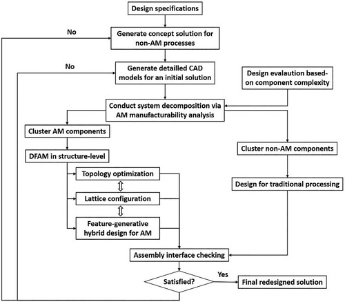
As shown in the design workflow (), before designing for AM tasks, an initial design is generated for the traditional manufacturing processes to exactly match the design specifications. The generated design solution is a typical traditional hydraulic system design, as illustrated in .
Figure 3. Initial design without oil pipe connection for traditional manufacturing processes.
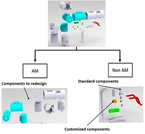
However, as discussed above, although the initial system could fulfil the functional requirements and be manufactured using traditional manufacturing processes, such as casting, machining, and drilling, it could not achieve the obvious weight and volume reduction required to compete with actuators using electric motors. Hence, to reduce the weight and volume, subsystem optimisation and the application of AM processing were required. This study aimed to use AM to help achieve the goals of weight reduction, system compactness, and performance improvement. To use AM, a system decomposition method was applied to decompose the original design solution system components into two main groups: the AM group for AM printing and the non-AM group for traditional manufacturing. The decomposition process was based on an AM design evaluation method. Component complexity was used as the main evaluation criterion for lightweight design. The features of AM and the component bounding boxes of the system’s initial components were used as inputs to calculate the design index values for checking the suitability of AM printing. Further details about the design evaluation method are reported in (Zhang et al. Citation2014). The decomposed result forms two main groups of components: one group to be redesigned for AM and the other group be manufactured by using traditional manufacturing in the form of customised components or selected from standard components. The decomposition and part clustering is presented in .
Figure 4. System decomposition for AM and non-AM processing.
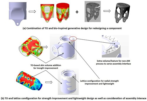
After checking the suitability of printing, all the AM components were analyzed using a clustering method to reduce the printing time and cost during prototyping. This method was also used to form sub-groups of AM components for design and printing preparation planning. The components were classified based on their dimensions and printing accuracy requirements. A grey clustering method was adopted; further details about this method can be found in the authors’ previous work (Zhang and Bernard Citation2014). After system decomposition, the cylinders and connection structures as well as the rotary shafts were identified as AM components because they could be redesigned for AM to reduce the weight and volume. To redesign these components, the topological optimisation (TO), lattice configuration and feature-based generative design for AM methods were applied in combination for different components or components’ sub-volumes. The progressive redesign method is derived from a structural redesign for AM method, as reported in author’s previous work (Wang et al. Citation2021). During the lightweight design process, at first, the components were analyzed and the strain/stress distribution was obtained. Thereafter, a classical TO was applied to obtain the volume skeleton of the components. Subsequently, lattice structures were used to fill and replace the solid volume to achieve weight reduction but ensure sufficient strength to maintain the mechanical performance of the components. The lattice configuration method was also adopted from the authors’ previous work (Lebaal et al. Citation2019), in which the anisotropic mechanical properties were obtained by adjusting the lattice cell parameters. Further details can be found in that reference. For redesigning the rotary cylinder hull, more strength is set in the radial direction to resist the pressure. And in the cylinder components’ skins, TO is used to determine the volume addition for increasing the strength. Multiple design for AM methods were used in combination to redesign the components in the AM group. In addition, to allow assembly, extra volumes were created for non-AM processing to create assembly interface features. Some examples for the design optimisation with the use of combined methods and consideration for assembly interface is given in .
Figure 5. Structure redesign for AM via combined design for AM methods: a. TO combines with generative design; b. TO combines with lattice configuration.
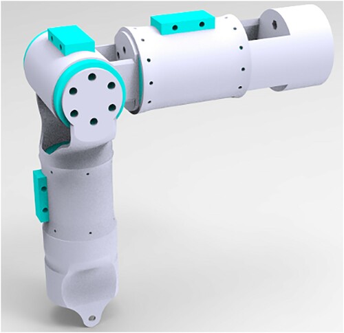
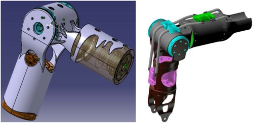
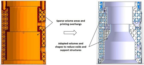
Following the progressive design for AM method, all the components in the AM group were redesigned, and an improved design was obtained, as illustrated in . These redesigned components were finally evaluated for manufacturability using the method proposed in (Shi et al. Citation2018) to be ready for printing with the M-PBF process. In fact, there were many design iterations, especially for the assembly interface consideration and printability problem. One design iteration example is given by .
Figure 6. Redesigned components of the AM component group of the actuator system (left) and the full actuator system (right).
After redesign the AM group components, other group components were selected by using standard components/raw materials or designed for machining. Then, assembly interface checking is conducted. if it does not work, the design iteration is launched and until to the conception stage. With an intensive design optimisation for many iterations, an optimal design solution was selected from a couple of alternatives (). The material used in this design to print the later prototype was a titanium alloy. The final design solution with a post-processing tolerant volume, except for the oil, has a total weight of less than 5 kg and can fit within the required bounding box. This is already better than actuators with electric motors because the system weight would be only 7 kg for this size. The following subsection introduces printing and post-processing for realising the physical prototype.
Figure 7. Example of consideration on strength and AM constraints for design adaptation.
2.2. M-PBF printing and post-processing
M-PBF is a metallic AM process. It can print components with good mechanical performances and shape accuracies. In this study, it was adopted to print the AM component group. The material and M-PBF machine with predefined printing parameters () are depicted in .
Figure 8. (a) Ti200 double-laser machine; (b) scanning electron microscopy image of Ti6Al4 V powder.
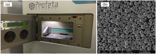
Table 1. Main printing parameter settings.
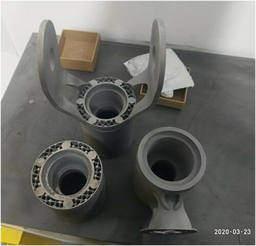
To ensure shape accuracy, the printing orientation was set along the axis direction for most of the components. depicts certain printed components in this group.
Figure 9. Printed components.
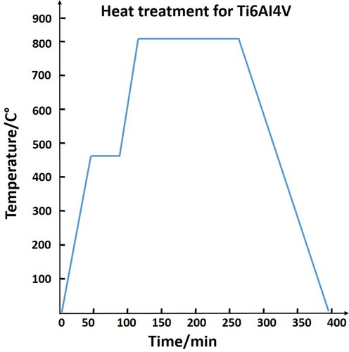
After printing, the components were sent for post-processing to improve the mechanical properties. Sanding and heat treatment were used in this study. The annealing process curve is presented in .
Figure 10. Annealing process curve for the printed components in Ti6Al4V material.
Finally, the AM group components need to be machined in the final post-processing step to create functional surfaces and assembled interfaces. The non-AM component groups are standard or customised components, which are manufactured through traditional processes. The physical prototype assembly for the functional test is described in Section 4.
3. Kinematics and torque analysis
The proposed 3-DOF robot actuator can be applied to various robot manipulators. For example, it could be a shoulder joint system in a 7-DOF humanoid robot arm. It can also be installed at the end of four- or five-axis robot manipulators to supplement their DOFs (Weyrich and Abdullah Citation2013). An analysis of the relationships between this 3-DOF robot actuator’s input and output is helpful for its functional testing and future application. This section describes the kinematics and torque analysis used to prepare for a functional test.
The tool centre point (TCP) is a special point at the end of a manipulator (Craig Citation2014). For coordinated motion and control, a mapping between the TCP coordinate system and the robot’s base coordinate system is required. The position and orientation of the TCP can be calculated using the joint angles with D-H parameters.
3.1. Forward kinematics
The proposed 3-DOF robot actuator can be regarded as a 3-DOF robot, and the modified D-H method is selected to describe the relationship between the 3D Cartesian space and the joint space. The position of a point and the orientation of a body are specified using three numbers in the 3D Cartesian space. Sometimes, this space is also referred to as the task space or operational space (Craig Citation2014).
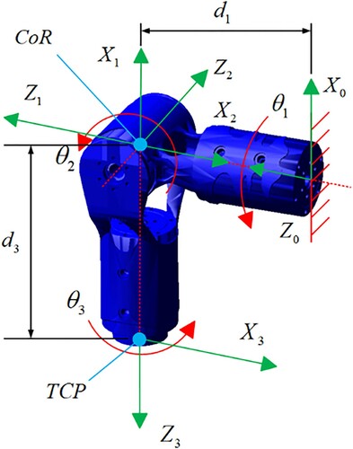
The D-H parameters of the proposed 3-DOF robot actuator can be defined as illustrated in . The geometric relation between axes 1 and 2 defines the centre of rotation. In this actuator, the values are set as and .
Figure 11. Schematic of the mechanical arm structure.
Six coordinates define the position and orientation of the TCP. Further, the 3-DOF robot actuator has three joints. These joint angles are represented in joint space as . Formula (1) expresses the transformation matrix from the joint space to the Cartesian space. The position of the TCP in the Cartesian space is presented as
. The orientation of the TCP can be expressed in terms of Euler angles, that is, the roll, pitch, and yaw angles. Further details can be found in (Spong, Hutchinson, and Vidyasagar Citation2020).
(1)
(1)
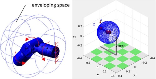
The position of the TCP in Cartesian space is distributed on a special spherical surface, and the radius of the spherical surface is ().
Figure 12. Position of TCP distributed on a special spherical surface.
Although the orientation of the TCP is expressed in terms of the Z-Y-Z Euler angles, the combined rotation matrix indicates that the coordinate system is rotated through angle
around the current Z-axis, then through angle
around the current Y-axis, and finally through angle
around the current Z-axis. Their interrelationship is expressed as follows:
(2)
(2)
By combining Equations Equation(1)(1)
(1) and Equation(2)
(2)
(2) :
(3)
(3)
It should be noted that when and
,
can be obtained as
; when
and
,
can be obtained as
.
Although the orientation of the TCP is expressed in terms of the roll, pitch, and yaw angles, and we specify the order of rotation as x-y-z, the combined rotation matrix indicates first a yaw about the X-axis through an angle
, then a pitch about the Y-axis through an angle
, and finally a roll about the Z-axis through an angle
. Their interrelationship is expressed as follows:
(4)
(4)
By combining Equations Equation(1)(1)
(1) and Equation(4)
(4)
(4) , we obtain the following expressions:
(5)
(5)
When and
,
can be calculated as
. When
,
,
can be calculated as
3.2. Inverse kinematics
The inverse kinematics problem is specified as follows: If the position and orientation of the TCP are known, all possible sets of joint angles that can be used to attain this given position and orientation can be calculated (Craig Citation2014). To implement the proposed actuator using the transformation matrix (1), the expressions for can easily be obtained by combining either Equations Equation(1)
(1)
(1) and Equation(3)
(3)
(3) or Equations Equation(1)
(1)
(1) and Equation(5)
(5)
(5) .
Two sets of inverse solutions can be obtained using EquationEquation (3)(3)
(3) . To obtain a set of reasonable solutions, we select the optimal solution by maintaining the continuity of the solution. We believe that in the actual running process, the actuator should run smoothly and the joint angles should not change suddenly.
3.3. Kinematic simulation
To compare the relationships between the 3-DOF robot actuator’s input and output, the input trajectories of the joint angles are expressed as follows:
(6)
(6) where
represents the running time of the actuator. presents the relationship between the joint angles and the position and orientation of the TCP for 10 s. Because the Z-Y-Z Euler angle is consistent with the inverse kinematics expression, there can be no discontinuities in the solution process. The Z-Y-Z Euler angle curve is consistent with the input trajectory, which verifies that the 3-DOF robot actuator can control the designated orientation with respect to space well. The four representative orientations are depicted in . The parameter values, including the joint angles and the position and orientation of the TCP, are listed in . The simulated relationship demonstrates that when the joint angles are determined, the position and orientation of the TCP are unique and can be precisely controlled.
Figure 13. Simulation curves of the position relationship between the TCP in space and the driving joint.
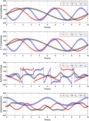
Figure 14. Four representative orientations of the 3-DOF robot actuator.
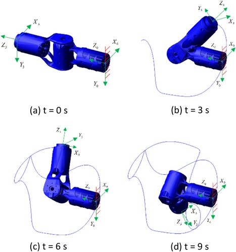
Table 2. Parameter values of the 3-DOF robot actuator.
3.4. Torque analysis
Based on the principle of hydraulic drives, the two most critical output quantities for hydraulic joints – output torque and output speed – can be obtained (Zhang Citation2010). The torque of each axis can be increased by adjusting the pressure, and the output speed of the joint can be adjusted by adjusting the flow rate of the hydraulic valve. In the existing prototype, the torque sensors and position sensors were not embedded in the joints. This study is focused on the feasibility of using AM to design and manufacture a functional prototype. Hence, this prototype cannot realise closed-loop control temporarily. Research in this direction is in progress, and the authors intend to report their findings in a future paper.
4. Prototype validation and discussion
4.1. Performance test
To test a single-joint’s performance, several experiments were set up.
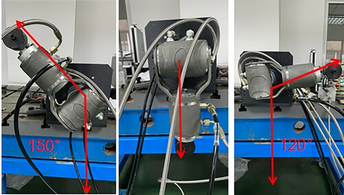
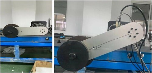
The experiments were conducted based on the designed range of motion. illustrates that the single-joint motion ranges up to 270°.
Figure 15. Single-joint motion range experiment.
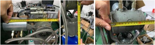
When the three joints are placed orthogonally, the space occupied by the entire prototype system is approximately 200 mm × 130 mm × 240 mm, as illustrated in . This result matches the bounding box requirement set in the design stage, which implies that there is an improvement in the compactness of the system.
Figure 16. Prototype dimension measurement as part of the testing.
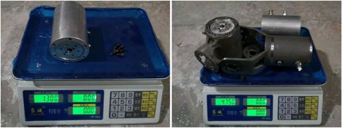
Before assembling the prototype, there was no hydraulic oil or pipe. The weight of the single-joint was 1.3 kg, and the total weight was 4.75 kg as shown in . These results meet the weight requirements set in the design stage.
Figure 17. Weight measurement.
In the design stage, the hydraulic pressure was set to 10 MPa. In the actual test, when the hydraulic pressure value was set to 12 MPa, higher than the nominal pressure, the joints could still operate normally, and the maximum single-axis torque reached 93 N·m. shows the experimental test.
Figure 18. Torque measurement experiment.
4.2. Application scenario test
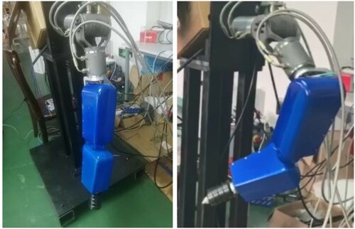
A physical prototype of the 3-DOF hydraulic robotic actuator system was applied to a seven-axis robot arm through connections with four other electric motor joints. The hydraulic system is used as the robot’s shoulder to execute large-range movements, and the left electric motor joints are used to perform accurate position adjustment and manipulate the robot’s TCP. The experiment indicated that the hydraulic shoulders can exactly realise the planned trajectories. In addition, they can achieve better loading capabilities with reduced weight and improved compactness when compared with electric motors. These functional test observations indicate that the use of the AM process to develop lightweight, high-performance hydraulic actuators is feasible and has significant application potential ().
Figure 19. Application scenario test.
4.3. Discussion
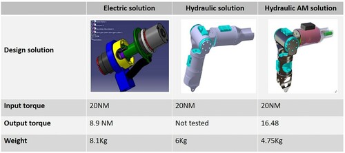
The tests and experiments described indicate that the proposed novel hydraulic actuator exhibits better performance when compared with a system using pure electric motors, especially for the load-to-weight ratio. The kinematics analysis and performance characterisation indicate that the adopted AM design and printing method accord the developed hydraulic robotic actuator significant application potential. To show the benefits brought by using AM, three design solutions for the project are compared as shown in , the first prototype is a pure electric motor solution, which uses two electric motors and regular shape connection components. Its main weight is from the motors except the control units. As said above, electric motor solution has high risk of fire for the operation tasks in the oil tank. In addition, its load-to-weight ratio is the worst, which cause performance degradation for the whole robot arm system. While for the hydraulic solutions, only the AM oriented one was prototyped as introduced above. It can be clearly seen that a clear improvement of the load-to-weight ratio was archived via the use of AM since the output torque of the two hydraulic solutions would be similar for the use of the same power system. Concerning the use of traditional machined gear pairs in the rotary cylinders for the current prototype, redesign and printing via AM can further bring reduced weight. In the next prototype, high-performance polymer materials with special chemical additions and surface treatments will be used to print gear pairs for the rotary cylinders to further reduce weight and improve lubrication properties. Hence, the hydraulic AM solution may appear more advantages.
Figure 20. Solution comparison.
As mentioned above, the existing AM-printed structures do not have any embedded control elements yet. Embedded printing may significantly improve the current prototype to enable the system to have smart control, monitoring, and perception. In addition, the range of motion of each axis can be further improved if the oil pipes can be concealed well within the structures through the use of rotary connections at the joint interface. In terms of spatial structure distribution, a more compact design can be obtained to establish a special D-H matrix and a Jacobian conversion matrix to reduce the spatial size and weight of the entire joint. The design can be further optimised in terms of loading performance, and the mechanical performance of the entire joint can be improved by increasing the bearing capacities of the liquid pressure as well as of the shell. In this study, the physical prototype was printed using a titanium alloy, which is heavier than the aluminium alloy. The next step is to test the printing of an improved prototype using a special aluminium alloy, which may further reduce the system weight but maintain a similar performance. However, as discussed above, in this study, the focus is on feasibility studies, as the prototype is still in the early stage of development. Further research is required in this direction.
5. Conclusion
The proposed novel AM-printed hydraulic robotic actuator demonstrates that AM has the potential to help design and print light and compact robotic structures and actuators with improved functions. It is an interdisciplinary design and development project that requires the knowledge of multiple domains. There is a need to use combined design for AM methods as well as design for traditional manufacturing methods to enable the system-level design and global manufacturability. The current physical prototype already exhibits promising improved performance and further potential for various applications. However, the authors are still investigating improvements in embedding functional electronics into the printed structures to enable a higher level of integration of hydraulic, electronic, and sensing capabilities for the development of smart systems. The integration of electric and hydraulic control in the current prototype system will be reported in the near future. An improvement of the current system-level design method and its interdisciplinary design support platform is also under development.
Disclosure statement
No potential conflict of interest was reported by the author(s).
Additional information
Notes on contributors
Weijun Wang
Weijun Wang, now is working as an senior robotic engineer in the 21st Research Institute of China Electronics Technology Corporation, had bachelor and master's degree from Beihang University in 2007 and 2010 separately, had Phd degree in École Centrale Nantes in 2013. His research interest includes the optimal design and robust desgin of robot actuator, robot system etc.
Feng Tang
Feng Tang, is PhD candidate at the State Key Laboratory of Advanced Special Steel in Shanghai University. His research interests include additive manufacturing, hydraulic system design.
Chen Zheng
Chen Zheng, is currently an associate professor at the School of Mechanical Engineering of Northwestern Polytechnical University (NPU) in Xi'an, China. His main research topics are manufacturing system design, mechatronic systems engineering, knowledge-based engineering and PLM. He has published over 40 papers of international journals and international conferences.
Tian Xie
Tian Xie, now is working as an robotic engineer in the 21st Research Institute of China Electronics Technology Corporation, had a master's degree from China University of Petroleum (Beijing) in 2018. His research interest includs the robot structure design and robot application design
Chaoyang Ma
Chaoyang Ma, now is working as an robotic engineer in the 21st Research Institute of China Electronics Technology Corporation, had a master's degree from North China University of Technology in 2019 . His research interest the kinematics, trajectory planning and dynamics of serial robot and parallel robot.
Yicha Zhang
Dr. Yicha Zhang, is now associate professor at the University of Technology Berlfort-Montbeliard (UTBM). His main research topics include design, planning and optimization for additive manufacturing (AM). He was elected as an associate memeber of CIRP (International Academy for Production Engineering) in 2020 and awarded the the CIRP Taylor Medal for the contribution to the design & planning for AM in 2021.
References
- Boston Dynamics. n.d. “Boston Dynamics,” http://www.bostondynamics.com/.
- Craig, J. J. 2014. Introduction to Robotics: Mechanics and Control, Ch. 3. Upper Saddle River, NJ: Pearson Higher Education.
- Katz, B. G. 2018. “A Low Cost Modular Actuator for Dynamic Robots,” PhD diss., Dept. of Mechanical Engineering. Massachusetts Institute of Technology: Cambridge, MA, USA.
- Lebaal, N., Y. Zhang, F. Demoly, S. Roth, S. Gomes, and A. Bernard. 2019. “Optimised Lattice Structure Configuration for Additive Manufacturing.” CIRP Annals 68 (1): 117–120.
- Semini, C., J. Goldsmith, B. Ur Rehman, et al. 2015. “Design Overview of the Hydraulic Quadruped Robots HyQ2Max and HyQ2Centaur,” The Fourteenth Scandinavian International Conference on Fluid Power, Tampere, Finland, May 20–22.
- Shi, Y., Y. Zhang, S. Baek, W. D. Backer, and R. Harik. 2018. “Manufacturability Analysis for Additive Manufacturing Using a Novel Feature Recognition Technique.” Computer-Aided Design and Applications 15 (6): 941–952.
- Spong, M. W., S. Hutchinson, and M. Vidyasagar. 2020. Robot Modeling and Control. 2nd ed. Hoboken, NJ: John Wiley & Sons.
- Suzumori, K., and A. A. Faudzi. 2018. “Trends in Hydraulic Actuators and Components in Legged and Tough Robots: A Review.” Advanced Robotics 32 (9): 458–476.
- Vaneker, T., A. Bernard, G. Moroni, I. Gibson, and Y. Zhang. 2020. “Design for Additive Manufacturing: Framework and Methodology.” CIRP Annals 69 (2): 578–599.
- Wang, W., C. Zheng, F. Tang, and Y. Zhang. 2021. “A Practical Redesign Method for Functional Additive Manufacturing.” Procedia CIRP 100: 566–570.
- Weyrich, M., and M. W. Abdullah. 2013. “Concept of a Three DOF Spherical-Joint Gripper for Industrial Robots,” 2013 IEEE 18th Conference on Emerging Technologies & Factory Automation (ETFA), Cagliari, Italy, 1–4.
- Zhang, P. 2010. Advanced Industrial Control Technology, Ch. 3. Windsor: William Andrew Publishing.
- Zhang, Y., and A. Bernard. 2014. “Grouping Parts for Multiple Parts Production in Additive Manufacturing.” Procedia CIRP 17: 308–313.
- Zhang, Y., A. Bernard, R. K. Gupta, and R. Harik. 2014. “Evaluating the Design for Additive Manufacturing: A Process Planning Perspective.” Procedia CIRP 21: 144–150.
