
 ?Mathematical formulae have been encoded as MathML and are displayed in this HTML version using MathJax in order to improve their display. Uncheck the box to turn MathJax off. This feature requires Javascript. Click on a formula to zoom.
ABSTRACT
Lattice structures are widely used in the industry for aerospace, automotive and biomedical applications as they are strong yet lightweight. Due to the complex geometry, lattice structures are mostly fabricated with additive manufacturing (AM). Despite AM having many advantages compared to traditional manufacturing methods, defects such as cracks and pores are commonly found in AM-produced samples, which could affect their actual performance. Thus, in this work, finite element analysis (FEA) is used to study the mechanical performances of in-situ alloyed titanium-tantalum (TiTa) lattice structures fabricated using laser powder bed fusion (L-PBF). Based on the established experimental data, the CAD models of the as-fabricated samples are reproduced and analysed using two modelling approaches. It is found that the elastic modulus is well-predicted by both simulation methods with high accuracy, while the yield strength is highly underpredicted by the two models for around 50% and 65% respectively. The FEA model is then used to analyse the performances of uniform lattice structures with 50% to 90% porosity and the results are found in agreement with the Gibson-Ashby model. To further improve the prediction accuracy of the simulation, more information on the defect condition is needed.
1. Introduction
In engineering, a lattice structure is an architecture consisting of repeated unit cells in two or three-dimensional space (Helou and Kara Citation2018). It is usually nature-inspired and well-known for its high strength and lightweight properties. More interestingly, the mechanical properties, such as yield strength and elastic modulus, are highly determined by the lattice type and design parameters (Maconachie et al. Citation2019; Choy et al. Citation2021). This characteristic allows engineering products to be designed with higher flexibility and capabilities (Daskalakis et al. Citation2021; Attarilar et al. Citation2020). As an example, in biomedical engineering, mismatch of mechanical properties between the implant and adjacent tissues could result in severe health impairment, such as micro-injuries, cell damage, inflammation, fibrosis or necrosis to the patients (Mazza and Ehret Citation2015). By integrating biomedical implants with lattice structures, similar strength to human bone can be achieved, thus reducing the problem of incompatibility (Sing Citation2022). Other than the biomedical sector (Zhang, Attarilar, et al. Citation2021), lattice structures are also widely used in aerospace and automobile components to reduce weight while retaining the components’ strength (Riva, Ginestra, and Ceretti Citation2021; Zhang, Huang, et al. Citation2021).
In the design of lattice structures, the ability to predict the actual performance before fabrication is especially important. Theoretical modelling, such as Gibson-Ashby model, is a commonly used method that relates the mechanical and thermal properties to the porosity of the lattice structure (Uhlířová and Pabst Citation2019). Owing to its simplicity in application, the Gibson-Ashby model is often used for preliminary estimation of the lattice performance. To have more comprehensive information on the lattice performances, computational models, such as finite element analysis (FEA), can be chosen. Instead of simply relating the mechanical performances to the lattice design parameters, FEA divides the whole domain into smaller parts and solves partially differential equations using numerical methods (Hughes Citation2012). Thus, it is more capable in simulating the mechanical behaviours of structure with complex geometry. A novel property mapping strategy was developed by Sindinger et al. (Sindinger et al. Citation2021) to study the thickness-dependent anisotropy of thin-walled components using FEA. By carefully setting up the numerical simulation, failure mode, for example buckling of the lattice structures can even be identified (Li et al. Citation2018). Based on FEA, many topology optimisation methods for lattice structure have been designed, for example, bidirectional evolutionary structural optimisation method (He, Zhang, and Song Citation2015), size gradient method (Han and Lu Citation2018) and generative design optimisation method (Li et al. Citation2018).
While FEA is often used for designing lattice structures, the actual mechanical performance can be significantly different from the simulation results due to unavoidable manufacturing defects. In the fabrication of lattice structures, additive manufacturing (AM), in particular selective laser melting (SLM), is mostly selected due to its capability in producing complex geometries in high resolution (Sing, Kuo, et al. Citation2021; Sun et al. Citation2022; Yu et al. Citation2022). Although SLM, also known as laser powder bed fusion (L-PBF), has a lot of advantages compared to the conventional manufacturing process, defects such as lack-of-fusion, keyhole porosity, balling and trapped gas are commonly found in AM components, which could result in degradation of mechanical properties (Galy et al. Citation2018; Kuo et al. Citation2020). The formation and elimination of the defects are extensively studied in recent years. Gong et al. (Citation2014) reported that gas bubbles can be generated from the vaporisation of alloy constituents with low melting points, which causes porosities to the fabricated components. Vapourization of volatile elements can also cause changes in alloy composition and explosion-induced-craters (Yin et al. Citation2021). Zhang, Li, and Bai (Citation2017) found that excess or insufficient laser power could cause unwanted surface irregularity due to the adhesion of partially melted powder to the surface of the components. The effect of different scanning strategies on the microstructure and mechanical properties of Inconel 718 alloy were studied by Sun et al. (Citation2020). They found that the grain growth characteristics are highly affected by the scanning strategies and the Rot-scan is efficient in improving the parts’ density.
On the other hand, there is a growing trend toward using in-situ alloying with L-PBF to fabricate alloy parts. In-situ alloying is a novel alloy synthesis method in L-PBF, where mixed powder feedstocks are used for fabricating functional parts instead of pre-alloyed powders. Such a manufacturing method allows a huge number of elemental combinations to be explored at relatively low cost and high flexibility (Knieps et al. Citation2021). However, it was reported that other than the common defects from the L-PBF manufacturing process, in-situ alloying might result in additional complications (Sing, Huang, et al. Citation2021). As reported by Kang et al. (Citation2017), higher input energy density is needed to produce full-dense Al–Si parts from mixed powder feedstock compared to pre-alloyed powder feedstock, which could further promote the vapourization of alloying elements. Simonelli et al. (Citation2018) compared the microstructures of in-situ alloyed Ti6Al4V parts fabricated with different powder mixing methods (i.e. direct mixing or satelliting method) and found that the inhomogeneity of feedstocks induces a random distribution of segregates in the microstructure. These additional defects from in-situ alloying increase the difficulty in predicting the performances of the fabricated parts through FEA.
In this work, a comparison between the computational simulation and actual experimental results of in-situ alloyed titanium-tantalum (TiTa) lattice structures fabricated by L-PBF is studied. Two commonly employed FEA modelling methods, namely the beam model and the full-3D model are used to simulate the mechanical behaviours of the lattice structures under compressive load. The lattice structure properties, such as elastic modulus and yield strength, obtained from the simulations are compared to established experimental data. Uniform lattice structures of porosity from 50% to 90% are then modelled using full-3D model and the effect of porosity on mechanical properties of lattice structures is discussed.
2. Experimental data and theory
2.1. Measurement and material properties
The experimental data used in this work was conducted by Sing, Wiria, and Yeong (Citation2018). shows the different planes of an as-fabricated lattice sample and their corresponding CAD models. The samples are based on the design of strut-based lattice structure, and they are fabricated using L-PBF and in-situ alloying approach. The materials used are a mixture of pure titanium and tantalum powders with a 1:1 weight ratio. The designed unit cell consists of vertical, horizontal, and diagonal struts with square cross-sections of 0.08 mm sides, as shown in . The dimension of the unit cell is while the dimension of the overall lattice structure is
. Different combinations of laser power (120, 240 and 360 W), laser scanning speed (400, 800 and 1200 mm/s) and layer thickness (0.03, 0.05 and 0.1 mm) are used for the L-PBF process. The actual strut thickness of the printed samples is then measured using an optical microscope while corresponding mechanical properties are obtained from the compressive test. As reported in the experiment study, not all combinations of processing parameters can produce lattice samples with continuous struts. Hence, five sets of samples, which have been reported to have continuous struts, are chosen to be studied in this work. The processing parameters of the selected samples are summarised in . The measured strut thickness of the samples is presented in while the corresponding positions of the measurements are labelled in the CAD models shown in .
Figure 1. (a) x-z plane, (b) y-z plane and (c) x-y plane of the in-situ alloyed TiTa lattice sample; (d), (e) and (f) show the corresponding planes of the representative CAD models.
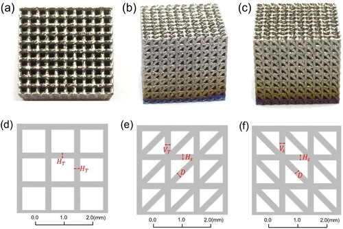
Figure 2. CAD model of the designed unit cell.
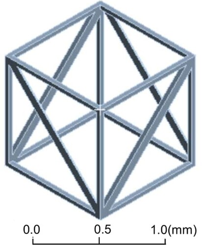
Figure 3. Strut thickness of the selected lattice samples.
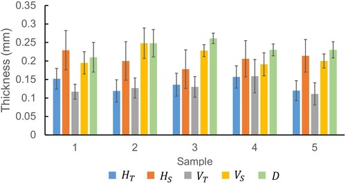
Table 1. Processing parameters of the selected lattice samples.
2.2. Gibson-Ashby model
Using Gibson-Ashby model, the mechanical properties of the lattice structures, for example elastic modulus and yield strength can be predicted based on their porosity (Gibbson and Ashby Citation1997):
(1)
(1)
(2)
(2) The
, and
correspond to the elastic modulus, yield strength and density of the lattice structure respectively, while the
, and
are the elastic modulus, yield strength and density of the full dense material.
is the porosity of the lattice structure which can be calculated as the fraction of void volume to the total nominal volume.
and
are the constants related to the lattice characteristics and can be obtained from compression test. shows the material properties of the in-situ alloyed TiTa.
Table 2. Nominal material properties of in-situ alloyed TiTa.
3. Finite element modelling and analysis
Based on the measured strut thickness, the CAD models of the five printed samples are reproduced to be used for FEA. The modelling and analysis of the lattice samples are done in ANSYS Mechanical APDL R2 software. In this work, two commonly used modelling methods, namely the beam model and full-3D model, are employed and the details of the two models are described in the following sections.
3.1. Material
As there is no information on TiTa alloy in ANSYS material database, the mechanical properties of the material are manually input. The density and the elasticity modulus used for TiTa are in , which are the data obtained from in-situ alloyed TiTa block samples. A bilinear elastic-plastic material model is used for the deformation of TiTa and the tangent modulus is assumed to be similar to Ti6Al4V alloy, which has a value of 1.25 GPa (Ziaja Citation2009).
3.2. Beam model
For the beam model, the struts are modelled as line bodies and rectangular cross sections are assigned to the line bodies according to the reported strut thickness in . To reduce the overall computational cost, lattices are used to represent the experimental samples, where each unit cell has a dimension of
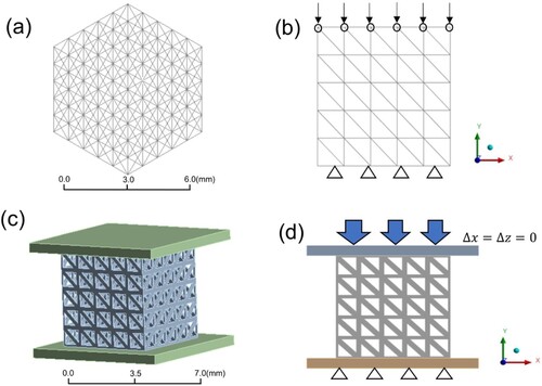
, similar to the experimental samples ((a)). A mesh convergence test is conducted to determine the optimal mesh size of the simulation models, and the resulting mesh of the beam models is found to have around 3500 elements. To study the stress–strain characteristic of the lattice models, a compressive load is applied on the nodes at the top surface, while the motion of the strut members at the bottom surface is fixed in all degrees of freedom ((b)). All the strut members are joint-connected with each other, and the total deformation of the lattice structures in y-direction is recorded as a function of compressive load.
Figure 4. (a) and (b) show the CAD model and boundary conditions for beam finite element simulation model. (c) and (d) show the CAD model and boundary conditions for full-3D finite element simulation model.
3.3. Full-3D model
For the full-3D model, top and bottom rigid plates are added, and all the struts are modelled as solid bodies ((c)). Similar to the beam model, the simulation lattice model has an overall dimension of . With the mesh convergence test, the optimal mesh element number is found to be around 40,000. The compressive load is applied on the upper surface of the top plate, while the motion of the bottom plate is fixed in all degrees of freedom ((d)). The top and bottom plates are connected to the lattice model through bonded contact. Lastly the vertical motion of the top plate is measured as a function of compressive load.
4. Results and discussions
4.1. Simulated mechanical behaviour of experiment samples
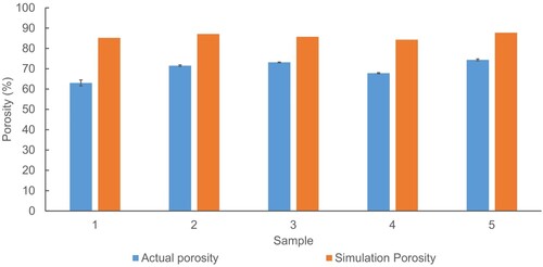
Based on the CAD model, the porosity of the five simulation models is calculated and compared with actual samples in . The porosity of the actual sample is calculated from the relative density with , where
is obtained by dividing the actual weight of the samples by their volume. The porosity of the simulation models is around 10–20% higher than the actual porosity measured from the experiment. The deviation is mainly because in the actual printed samples, there are partially melted powders adhered to the struts, which are not considered in the actual strut thickness. These particles thus give extra volume to the lattice structure and decrease the overall porosity of the experimental samples. Also, for the CAD models, the struts at the boundary faces of the whole lattice structure are designed to have only half of the regular thickness. It is, however, not realisable in actual printed samples due to the finite size of the laser spot and melt pool. These two reasons cause the actual samples to have a higher volume compared to the simulation models.
Figure 5. Comparison of actual porosity to the simulation porosity.
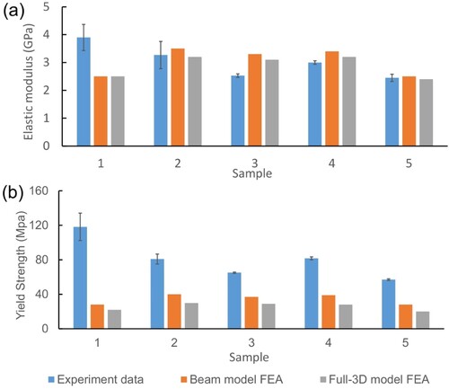
In (a,b), the deformations of lattice sample 3 under 1200 N compressive load are illustrated using beam model and full-3D model. Compared to the beam model, the full-3D model is capable of capturing the local stress ((c)). It can be seen that most of the stress is concentrated in the vertical struts, suggesting that reinforcement can be done on these regions to improve the overall lattice performances. A typical stress–strain curve from FEA simulation using the bilinear elastic-plastic material model is shown in . The lattice structure deforms elastically under small applied stress, followed by plastic deformation under high applied stress. From the corresponding stress–strain curves, the elastic modulus and yield strength are extracted and plotted in (a,b). For the elastic modulus, both the beam model and full-3D model can predict the actual data with reasonably well accuracy. Not much difference is found between the prediction from the beam model and the full-3D model, suggesting that both models are equally well in predicting the actual elastic modulus. While for the yield strength, the experimental values are found underpredicted by the beam model and full-3D model for around 50% and 65% respectively. The deviation between the yield strength of the actual samples and simulation models might be due to several reasons. Firstly, as mentioned, there are partially melted particles adhering to the struts, which increase the roughness of the struts as well as the overall strut volume. In the simulation models, such non-uniformity is not considered and the struts are only characterised by the average measured thickness. These additional volumes can effectively provide resistance to the compressive load and increase the compressive yield strength of the as-fabricated samples. Secondly, residual stress is a common defect found in L-PBF parts, especially those with overhang structures, due to the thermal variations of the fabrication process. Tensile residual stress in the samples can offset the applied compressive stress and result in a higher compressive yield strength. To minimise the effect of surface non-uniformity and residual stress on the mechanical properties of the lattice samples, heat treatment can be used to promote the bonding of the partially melted particles to the fully melted struts, as well as relieve the internal residual stress (Sing, Wiria, and Yeong Citation2018). This would improve the surface texture and the uniformity of the samples, allowing the simulated results to better match the actual mechanical properties. In the future, such defects can also be considered in the simulations for better accuracy.
Figure 6. (a) and (b) illustrate the deformation of lattice structure simulated using the beam model and full-3D model respectively. (c) shows the corresponding von-Mises stress for the full-3D model.
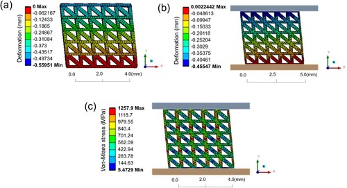
Figure 7. A typical stress-strain curve from the finite element simulation with the bilinear elastic-plastic material model.
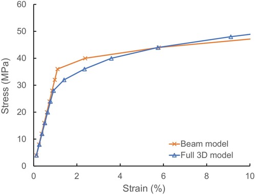
Figure 8. Comparison of the (a) elastic modulus and (b) yield strength of the experimental data to the FEA results of beam model and full-3D models.
4.2. Effect of porosity on mechanical properties
Porosity is a major factor in determining the mechanical properties of lattice structures and it is extensively studied in many literatures (Al-Maharma, Patil, and Markert Citation2020). Here, lattice structures with completely uniform strut thickness (i.e. ) are modelled in five different porosities (50% to 90%) and analysed with the full-3D FEA model to understand how porosity affects the elastic modulus and yield strength of the structures. The corresponding strut thickness and mechanical performance of the simulation models are summarised in . The elastic modulus and yield strength are then fitted with the Gibson-Ashby model, as shown in . It can be seen that both the elastic modulus and yield strength are well-fitted into the Gibson-Ashby model with relatively high
of 0.9956 and 0.9776 respectively. This suggests that the full-3D FEA model is capable of capturing the relationship between the porosity and the mechanical properties of the lattice structures. From , the constant terms in the Gibson-Ashby model with this particular lattice structure are found to be
and
Figure 9. (a) Elastic modulus and (b) yield strength fitted with the Gibson-Ashby model.
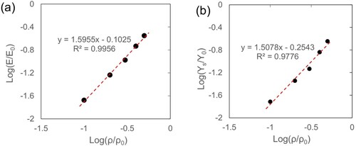
Table 3. Strut thickness and mechanical properties obtained from the full-3D model for uniform lattice structures with different porosity.
Interestingly, for the uniform lattice structures with 60% and 70% porosity, the full-3D FEA model predicts a yield strength of 128 and 65 MPa respectively. These predictions are very close to the yield strength of the actual samples which have porosity between 60% and 75%. This suggests that the yield strength might be more related to the actual porosity instead of the strut geometry. It is, however, not the case for the elastic modulus. Based on the full-3D model, the elastic modulus is predicted to be 14 and 8 GPa for uniform lattice structure with 60% and 70% porosity, which are significantly higher than the experimental value. The elastic modulus thus is more likely to be depending on the actual thickness of the complete strut instead of the porosity.
5. Discussion and future work
5.1. Model simplification
In predicting the mechanical properties of the lattice structure using FEA, the trade-off between the computational expense and accuracy is an important factor to be considered. In this work, two models, namely the beam model and full-3D model are used to simulate the deformation of the TiTa lattice structures. While the beam model has much lesser mesh elements, the simulation results are comparable to the one from the full-3D model. This suggests that the beam model is a good representation of the full-3D model in our cases. In another approach done by Hu, Seetoh, and Lai (Citation2022), the body-centered cubic (BCC) and Octet Truss lattices are reduced to a single-beam subcell model. With the single-beam subcell model, the computational time for performing FEA is again reduced, and the stiffness and strength are found highly agree with the results obtained from the full-lattice models. Although the single-beam subcell model is only applicable to those lattices formed with inclined beams, it is worth to be extended for simulating lattices with more complex geometry.
On the other hand, despite reducing the number of the lattice units for simulation can effectively decrease the computational expense, the mechanical properties of lattice structures with few unit cells might be significantly different from the actual bulk properties. Yoder, Thompson, and Summers (Citation2018) reported that for a fixed unit cell size, as the sample size decrease, more material volume is distributed at the lattice boundary. This results in different sample properties from the bulk properties, which is also known as the size effect. With increasing sample size, the properties of the lattice sample increase asymptotically to the bulk properties. There are different types of size effects, depending on the types of loads and distribution of materials, and these effects are extensively studied in many of the literature (Yan et al. Citation2014; Mancusi et al. Citation2017). An analysis can thus be done in the future to compare the difference between the lattice models used in this work to the corresponding
lattice models.
5.2. Defects in lattice structure
Other than the porosity difference mentioned in the previous sections, there are some other manufacturing defects that are commonly found in in-situ alloyed parts by L-PBF which require extra considerations. Echeta et al. (Citation2021) modelled the form and surface defects, such as strut waviness and surface roughness, using signed distance functions in FEA and studied the effect of these defects on the mechanical performances of different strut-based lattice structures. He reported that the compressive elastic modulus of lattice structures is reduced with texture bias, and the reduction is more significant for downskin defects. Residual stresses arisen from the high thermal gradient and cooling rates of the L-PBF process can also induce cracks and delamination of the layers to the lattice samples, which are detrimental to the lattices’ performances (Echeta et al. Citation2020). On the other hand, segregation and vapourization of alloying elements during the in-situ alloying process might result in extra porosity and composition inhomogeneity in the fabricated samples.
To account for these defects, many recent studies employed the defect statistical data obtained from the actual fabricated parts in the FEA simulations. For example, based on the micro-CT scan reconstruction data, Lei et al. (Citation2019) reconstructed the FEA model based on the statistical average diameter of struts, and they found that the prediction accuracy is improved. Similarly, Lozanovski et al. (Citation2020) used the geometrical information from micro-CT scans to generate random digital realisation of fabrication struts for FE modelling. With that, the effect of geometrical defects on the mechanical properties of lattice structure can be effectively studied. These examples show that the inclusion of realistic defects in the FEA model is necessary to better predict the mechanical performances of lattice structures.
5.3. Effect of pore size
From Gibson-Ashby model, it is known that the mechanical properties, for instance elastic modulus and yield strength increase exponentially with the relative density of the lattice structures. Such a relationship is illustrated through studying the effect of different lattice strut thickness in this work. In many real applications, pore size is also an important factor to be considered other than strut thickness. Pore size is usually defined as the diameter of the largest circle aligned with a lattice face which is not intersected by any of the beams. In biomedical applications, for example, tissue scaffolds and implants, pore size affects the surface-volume ratio and permeability of the structures, thus governing the bone tissue growth rate and fluid flow for nutrient transport (Zhang et al. Citation2022; Egan et al. Citation2017). Typically, pore sizes between 200 and 800 µm can facilitate the growth of bone tissues. Thus, the effect of pore size on the lattice properties, as well as the prediction accuracy of the FEA model, can be studied in the future.
6. Conclusion
In this work, two of the commonly used FEA modelling methods, namely the beam model and full-3D model, are employed to simulate the mechanical behaviours of in-situ alloyed TiTa lattice structures under compressive load. The elastic modulus and yield strength of the lattice structures are analysed and compared to the established experimental data. Both the beam model and full-3D model are found to be equally good in predicting the elastic modulus of five sets of as-fabricated samples, while the actual yield strength is underpredicted by around 50% and 65% respectively. Such deviations are mainly due to the defects from the manufacturing process and unavoidably geometrical differences between the simulation models and the actual samples. To further validate the FEA model, uniform lattice structures of porosity from 50% to 90% are simulated using the full-3D model and the mechanical properties are found well-fitted to the Gibson-Ashby model. In the future, defects information, for example, surface roughness and strut waviness, can be extracted from the experiment samples and included in the simulation models so that the prediction accuracy of the FEA models can be further improved.
Acknowledgements
The authors would like to acknowledge the funding support from Singapore Ministry of Education Academic Research Fund Tier 1 (Award No.: 22-3721-A0001).
Disclosure statement
No potential conflict of interest was reported by the author(s).
Additional information
Funding
Notes on contributors
Cherq Chua
Cherq Chua is a PhD student from Engineering Product Development Pillar at Singapore University of Technology and Design (SUTD). He obtained First Class Honours for his bachelor's degree in Mechanical Engineering from National University of Singapore (NUS) in 2020. His research interests include finite element modeling and alloy design for metal additive manufacturing.
Swee Leong Sing
Swee Leong Sing is an Assistant Professor at the Department of Mechanical Engineering, National University of Singapore (NUS), Singapore. Prior to joining NUS, he was a Presidential Postdoctoral Fellow at the Singapore Centre for 3D Printing and School of Mechanical and Aerospace Engineering, Nanyang Technological University, Singapore after receiving the prestigious fellowship in 2020. His research interest is enabling material development and creating strategic values for Industry 4.0 and beyond through the use and integration of advanced manufacturing. As of October 2022, he has co-authored 57 peer reviewed articles in the field of additive manufacturing or 3D printing. He currently has a h-index of 32, with more than 5000 citations based on statistics from Web of Science. He is also the co-inventor for three patents in additive manufacturing.
C. K. Chua
Chee Kai Chua is the Associate Provost for Research and Cheng Tsang Man Chair Professor at the Singapore University of Technology and Design (SUTD). He is the foremost expert in Singapore in the field of Additive Manufacturing and was awarded the prestigious International Freeform and Additive Manufacturing Excellence (FAME) Award in 2018. According to the Web of Science, he is the most published and most cited scientist in ‘Rapid Prototyping / Additive Manufacturing', and he has published in more than 400 international journals, conference papers, books, book chapters and patents. He is also the Editor-in-Chief of both ‘Virtual and Physical Prototyping' and ‘International Journal of Bioprinting’.
References
- Al-Maharma, A. Y., S. P. Patil, and B. Markert. 2020. “Effects of Porosity on the Mechanical Properties of Additively Manufactured Components: A Critical Review.” Materials Research Express 7 (12): 122001. doi: 10.1088/2053-1591/abcc5d
- Attarilar, S., M. Ebrahimi, F. Djavanroodi, Y. Fu, L. Wang, and J. Yang. 2020. “3D Printing Technologies in Metallic Implants: A Thematic Review on the Techniques and Procedures.” International Journal of Bioprinting 7 (1): 306.
- Choy, S. Y., C.-N. Sun, W. J. Sin, K. F. Leong, P.-C. Su, J. Wei, and P. Wang. 2021. “Superior Energy Absorption of Continuously Graded Microlattices by Electron Beam Additive Manufacturing.” Virtual and Physical Prototyping 16 (1): 14–28. doi: 10.1080/17452759.2020.1868656
- Daskalakis, E., F. Liu, B. Huang, A. A. Acar, G. Cooper, A. Weightman, G. Blunn, B. Koç, and P. Bartolo. 2021. “Investigating the Influence of Architecture and Material Composition of 3D Printed Anatomical Design Scaffolds for Large Bone Defects.” International Journal of Bioprinting 7 (2): 268. doi: 10.18063/ijb.v7i2.268
- Echeta, I., B. Dutton, R. K. Leach, and S. Piano. 2021. “Finite Element Modelling of Defects in Additively Manufactured Strut-Based Lattice Structures.” Additive Manufacturing 47: 102301. doi: 10.1016/j.addma.2021.102301
- Echeta, I., X. Feng, B. Dutton, R. Leach, and S. Piano. 2020. “Review of Defects in Lattice Structures Manufactured by Powder bed Fusion.” The International Journal of Advanced Manufacturing Technology 106 (5): 2649–2668. doi: 10.1007/s00170-019-04753-4
- Egan, P. F., V. C. Gonella, M. Engensperger, S. J. Ferguson, and K. Shea. 2017. “Computationally Designed Lattices with Tuned Properties for Tissue Engineering Using 3D Printing.” PloS one 12 (8): e0182902. doi: 10.1371/journal.pone.0182902
- Galy, C., E. Le Guen, E. Lacoste, and C. Arvieu. 2018. “Main Defects Observed in Aluminum Alloy Parts Produced by SLM: From Causes to Consequences.” Additive Manufacturing 22: 165–175. doi: 10.1016/j.addma.2018.05.005
- Gibbson, L., and M. Ashby. 1997. Cellular Solid: Structure and Properties. New York: Cambridge Univ. Press.
- Gong, H., K. Rafi, H. Gu, T. Starr, and B. Stucker. 2014. “Analysis of Defect Generation in Ti–6Al–4V Parts Made Using Powder bed Fusion Additive Manufacturing Processes.” Additive Manufacturing 1-4: 87–98. doi: 10.1016/j.addma.2014.08.002
- Han, Y., and W. F. Lu. 2018. “A Novel Design Method for Nonuniform Lattice Structures Based on Topology Optimization.” Journal of Mechanical Design 140 (9): 091403. doi: 10.1115/1.4040546
- He, G., M. Zhang, and Z. Song. 2015. “Error Evaluation of Free-Form Surface Based on Distance Function of Measured Point to Surface.” Computer-Aided Design 65: 11–17. doi: 10.1016/j.cad.2015.02.004
- Helou, M., and S. Kara. 2018. “Design, Analysis and Manufacturing of Lattice Structures: An Overview.” International Journal of Computer Integrated Manufacturing 31 (3): 243–261. doi: 10.1080/0951192X.2017.1407456
- Hu, E., I. P. Seetoh, and C. Q. Lai. 2022. “Machine Learning Assisted Investigation of Defect Influence on the Mechanical Properties of Additively Manufactured Architected Materials.” International Journal of Mechanical Sciences 221: 107190. doi: 10.1016/j.ijmecsci.2022.107190
- Hughes, T. J. The Finite Element Method: Linear Static and Dynamic Finite Element Analysis: Courier Corporation; 2012.
- Kang, N., P. Coddet, L. Dembinski, H. Liao, and C. Coddet. 2017. “Microstructure and Strength Analysis of Eutectic Al-Si Alloy in-Situ Manufactured Using Selective Laser Melting from Elemental Powder Mixture.” Journal of Alloys and Compounds 691: 316–322. doi: 10.1016/j.jallcom.2016.08.249
- Knieps, M. S., W. J. Reynolds, J. Dejaune, A. T. Clare, and A. Evirgen. 2021. “In-situ Alloying in Powder bed Fusion: The Role of Powder Morphology.” Materials Science and Engineering: A 807: 140849. doi: 10.1016/j.msea.2021.140849
- Kuo, C., C. Chua, P. Peng, Y. Chen, S. Sing, S. Huang, and Y. L. Su. 2020. “Microstructure Evolution and Mechanical Property Response via 3D Printing Parameter Development of Al–Sc Alloy.” Virtual and Physical Prototyping 15 (1): 120–129. doi: 10.1080/17452759.2019.1698967
- Lei, H., C. Li, J. Meng, H. Zhou, Y. Liu, X. Zhang, P. Wang, and D. Fang. 2019. “Evaluation of Compressive Properties of SLM-Fabricated Multi-Layer Lattice Structures by Experimental Test and μ-CT-Based Finite Element Analysis.” Materials & Design 169: 107685. doi: 10.1016/j.matdes.2019.107685
- Li, C., H. Lei, Y. Liu, X. Zhang, J. Xiong, H. Zhou, and D. Fang. 2018a. “Crushing Behavior of Multi-Layer Metal Lattice Panel Fabricated by Selective Laser Melting.” International Journal of Mechanical Sciences 145: 389–399. doi: 10.1016/j.ijmecsci.2018.07.029
- Li, D., W. Liao, N. Dai, G. Dong, Y. Tang, and Y. M. Xie. 2018b. “Optimal Design and Modeling of Gyroid-Based Functionally Graded Cellular Structures for Additive Manufacturing.” Computer-Aided Design 104: 87–99. doi: 10.1016/j.cad.2018.06.003
- Lozanovski, B., D. Downing, P. Tran, D. Shidid, M. Qian, P. Choong, M. Brandt, and M. Leary. 2020. “A Monte Carlo Simulation-Based Approach to Realistic Modelling of Additively Manufactured Lattice Structures.” Additive Manufacturing 32: 101092. doi: 10.1016/j.addma.2020.101092
- Maconachie, T., M. Leary, B. Lozanovski, X. Zhang, M. Qian, O. Faruque, and M. Brandt. 2019. “SLM Lattice Structures: Properties, Performance, Applications and Challenges.” Materials & Design 183: 108137. doi: 10.1016/j.matdes.2019.108137
- Mancusi, G., F. Fabbrocino, L. Feo, and F. Fraternali. 2017. “Size Effect and Dynamic Properties of 2D Lattice Materials.” Composites Part B: Engineering 112: 235–242. doi: 10.1016/j.compositesb.2016.12.026
- Mazza, E., and A. E. Ehret. 2015. “Mechanical Biocompatibility of Highly Deformable Biomedical Materials.” Journal of the Mechanical Behavior of Biomedical Materials 48: 100–124. doi: 10.1016/j.jmbbm.2015.03.023
- Riva, L., P. S. Ginestra, and E. Ceretti. 2021. “Mechanical Characterization and Properties of Laser-Based Powder bed–Fused Lattice Structures: A Review.” The International Journal of Advanced Manufacturing Technology 113 (3): 649–671. doi: 10.1007/s00170-021-06631-4
- Simonelli, M., N. T. Aboulkhair, P. Cohen, J. W. Murray, A. T. Clare, C. Tuck, and R. J. M. Hague. 2018. “A Comparison of Ti-6Al-4V in-Situ Alloying in Selective Laser Melting Using Simply-Mixed and Satellited Powder Blend Feedstocks.” Materials Characterization 143: 118–126. doi: 10.1016/j.matchar.2018.05.039
- Sindinger, S.-L., D. Marschall, C. Kralovec, and M. Schagerl. 2021. “Material Modelling and Property Mapping for Structural FEA of Thin-Walled Additively Manufactured Components.” Virtual and Physical Prototyping 16 (1): 97–112. doi: 10.1080/17452759.2020.1824427
- Sing, S. L. 2022. “Perspectives on Additive Manufacturing Enabled Beta-Titanium Alloys for Biomedical Applications.” International Journal of Bioprinting 8 (1): 478. doi: 10.18063/ijb.v8i1.478
- Sing, S. L., S. Huang, G. D. Goh, G. L. Goh, C. F. Tey, J. H. K. Tan, and W. Y. Yeong. 2021. “Emerging Metallic Systems for Additive Manufacturing: In-Situ Alloying and Multi-Metal Processing in Laser Powder bed Fusion.” Progress in Materials Science 119: 100795. doi: 10.1016/j.pmatsci.2021.100795
- Sing, S., C. Kuo, C. Shih, C. Ho, and C. Chua. 2021. “Perspectives of Using Machine Learning in Laser Powder bed Fusion for Metal Additive Manufacturing.” Virtual and Physical Prototyping 16 (3): 372–386. doi: 10.1080/17452759.2021.1944229
- Sing, S. L., F. E. Wiria, and W. Y. Yeong. 2018. “Selective Laser Melting of Lattice Structures: A Statistical Approach to Manufacturability and Mechanical Behavior.” Robotics and Computer-Integrated Manufacturing 49: 170–180. doi: 10.1016/j.rcim.2017.06.006
- Sun, J., M. Guo, K. Shi, and D. Gu. 2022. “Influence of Powder Morphology on Laser Absorption Behavior and Printability of Nanoparticle-Coated 90W-Ni-Fe Powder During Laser Powder bed Fusion.” Materials Science in Additive Manufacturing 1 (2): 11. doi: 10.18063/msam.v1i2.11
- Sun, Q., K. Guo, X. Wang, J. Liu, and J. Sun. 2020. “Effect of Scanning Strategies on the Microstructure and Mechanical Behavior of 316L Stainless Steel Fabricated by Selective Laser Melting.” Materials Science and Engineering: A 793: 139879. doi: 10.1016/j.msea.2020.139879
- Uhlířová, T., and W. Pabst. 2019. “Conductivity and Young's Modulus of Porous Metamaterials Based on Gibson-Ashby Cells.” Scripta Materialia 159: 1–4. doi: 10.1016/j.scriptamat.2018.09.005
- Yan, J., W.-B. Hu, Z.-H. Wang, and Z.-Y. Duan. 2014. “Size Effect of Lattice Material and Minimum Weight Design.” Acta Mechanica Sinica 30 (2): 191–197. doi: 10.1007/s10409-014-0001-5
- Yin, J., W. Zhang, L. Ke, H. Wei, D. Wang, L. Yang, H. Zhu, P. Dong, G. Wang, and Z. Zeng. 2021. “Vaporization of Alloying Elements and Explosion Behavior During Laser Powder bed Fusion of Cu–10Zn Alloy.” International Journal of Machine Tools and Manufacture 161: 103686. doi: 10.1016/j.ijmachtools.2020.103686
- Yoder, M., L. Thompson, and J. Summers. 2018. “Size Effects in Lattice Structures and a Comparison to Micropolar Elasticity.” International Journal of Solids and Structures 143: 245–261. doi: 10.1016/j.ijsolstr.2018.03.013
- Yu, W., Z. Xiao, X. Zhang, Y. Sun, P. Xue, S. Tan, Y. Wu, and H. Zheng. 2022. “Processing and Characterization of Crack-Free 7075 Aluminum Alloys with Elemental Zr Modification by Laser Powder bed Fusion.” Materials Science in Additive Manufacturing 1 (1): 4. doi: 10.18063/msam.v1i1.4
- Zhang, Y., S. Attarilar, L. Wang, W. Lu, J. Yang, and Y. Fu. 2021. “A Review on Design and Mechanical Properties of Additively Manufactured NiTi Implants for Orthopedic Applications.” International Journal of Bioprinting 7 (2): 340. doi: 10.18063/ijb.v7i2.340
- Zhang, J., H. Huang, G. Liu, H. Zong, and C. Zhang. 2021. “Stiffness and Energy Absorption of Additive Manufactured Hybrid Lattice Structures.” Virtual and Physical Prototyping 16 (4): 428–443. doi: 10.1080/17452759.2021.1954405
- Zhang, B., Y. Li, and Q. Bai. 2017. “Defect Formation Mechanisms in Selective Laser Melting: A Review.” Chinese Journal of Mechanical Engineering 30 (3): 515–527. doi: 10.1007/s10033-017-0121-5
- Zhang, J., Y. Shen, Y. Sun, J. Yang, Y. Gong, K. Wang, Z. Zhang, X. Chen, and L. Bai. 2022. “Design and Mechanical Testing of Porous Lattice Structure with Independent Adjustment of Pore Size and Porosity for Bone Implant.” Journal of Materials Research and Technology 18: 3240–3255. doi: 10.1016/j.jmrt.2022.04.002
- Ziaja, W. 2009. “Finite Element Modelling of the Fracture Behaviour of Surface Treated Ti-6Al-4V Alloy.” Computational Materials Science and Surface Engineering 16: 17.