
 ?Mathematical formulae have been encoded as MathML and are displayed in this HTML version using MathJax in order to improve their display. Uncheck the box to turn MathJax off. This feature requires Javascript. Click on a formula to zoom.
ABSTRACT
Multifunctional metamaterials with unique electromagnetic and mechanical properties are highly desired in many fields, including space exploration and satellite communication, where broad tunability of the working frequency and controllable mechanical deformation properties are usually necessary. In this study, we propose a metasurface exhibiting simultaneous electromagnetic frequency selection capability and isotropic negative/positive/near-zero thermal expansion. The metasurface is designed based on chiral structures and is fabricated via 4D printing of continuous fibre composites. Both the effective thermal expansion coefficient and electromagnetic transmission band were investigated in different structural parameters based on theoretical calculation, finite element analysis simulations and experiments. The measured results were in good agreement with the theoretical data which reveal the influence law of structural parameters on thermal deformation and electromagnetic frequency control. Thus, the electromagnetic functionality of the metasurface can be thermally controlled and is expected to be useful in extreme situations where the coupling of multiphysical fields is required.
1. Introduction
The concept of metamaterials was first proposed in the electromagnetic (EM) domain (Surjadi et al. Citation2019; Wu et al. Citation2019; Zheludev Citation2010), and the frequency control of the transmissive (Fan et al. Citation2020; Stephen, Yogesh, and Subramanian Citation2018) or reflective (Liu et al. Citation2021; Yin et al. Citation2019) properties is one of the most significant applications of EM metamaterials and has been widely used in the design of wave filters, antennas, etc. However, despite their remarkable performance, most EM metamaterials are designed with a fixed response that cannot be adjusted based on changes in the environment, such as a sudden decrease/increase in temperature or pressure. Therefore, the development of EM metamaterials with programmable deformation capability is crucial to creating novel devices with versatile and flexible functionalities.
Recently, significant efforts have been focused on developing multifunctional metamaterials with two or more extraordinary properties (Lewi, Butakov, and Schuller Citation2019; Lor et al. Citation2022; Rahmani et al. Citation2017; Xu et al. Citation2020) due to the need for versatility in multiphysical coupling environments. Metamaterials with multifunctional, cross-physical field, and dynamic response have been motivated by the gradual application of metamaterials in the fields of acoustics (Mizukami et al. Citation2021; Wu et al. Citation2022), thermal (Chen et al. Citation2021; Guo et al. Citation2022; Wei et al. Citation2016), mechanical (Mizukami, Funaba, and Ogi Citation2021; Wang et al. Citation2023; Xu et al. Citation2022), electrostatic (Hu et al. Citation2016; Ren et al. Citation2020; Zeng, Wu, and Werner Citation2010), etc. Thermal deformation has been extensively utilised to control the configuration of structures, especially in space exploration (Ma et al. Citation2022; Toropova and Steeves Citation2015; Wei et al. Citation2018), where there are significant temperature difference depending on the extraterrestrial environment. By combining two or more materials with different coefficients of thermal expansion (CTE), mechanical metamaterials with positive/negative or even zero thermal expansion behaviour can be realised (Wang et al. Citation2022; Wei et al. Citation2018; Wei et al. Citation2021), which are ideal for integration with EM metamaterials.
Furthermore, the rapid development of advanced manufacturing technologies such as 3D/4D printing (Bai et al. Citation2022; Tian et al. Citation2022; Tibbits Citation2014; Wei et al. Citation2021), two-photon lithography (Qu et al. Citation2017; Wang et al. Citation2016; Yamamoto et al. Citation2014), etc., has significantly advanced metamaterial research. 4D printing, in particular, adds the dimension of time to 3D printing (Wang et al. Citation2018; Zeng et al. Citation2022). This means that objects fabricated via 3D printing can be deformed obviously over time under the stimulus of an external environment, which is ideal for the preparation of tunable metamaterials. In addition, additive manufacturing technology allows for the integration of material, structure, and performance (Gu Citation2022; Gu et al. Citation2021), making it advantageous for the production of high-performance and multifunctional metamaterials.
In this report, we propose a bifunctional metamaterial with unique EM and mechanical performance. The carefully designed structure of the metasurface enables thermal tunability of its EM transmission. The metasurface is composed of chiral elements that combine anisotropic continuous carbon fibre (CCF), with a low CTE/high conductivity along the fibre direction, and polyamides (PA), with a high CTE/low conductivity, which can be fabricated via 4D printing of continuous fibre composites to fully exploit the anisotropy (Chen et al. Citation2022; Goh et al. Citation2021; Somireddy and Czekanski Citation2020). By appropriately selecting the geometric size of the chiral elements and arranging the position of the carbon fibre/PA, the metasurface could theoretically exhibit negative, positive, or even near-zero thermal expansion, which could be employed to regulate EM transmission in practical applications. Additionally, the zero expansion feature allows the metasurface to maintain stable under large temperature difference in space. The metasurface proposed in this study not only offers functional advantages, but also benefits from a very flexible and efficient fabrication process.
2. Theory and experiment
2.1. Conception and design
A thermally tunable metasurface is a 2D chiral metamaterial composed of periodic bi-material curved beams in a rotational array. As illustrated in (a), the metasurface has two states: a shrinkage state and an expanded state. The former has a larger curvature than the latter, with an equal arc length. It is assumed that the metasurface shrinks at temperature Ts with several specific arc geometric parameters (arc radius Rs, arc angle θs, chord length Ls) and a different set of parameters (arc radius Re, arc angle θe, chord length Le) in an expanded state at temperature Te. The curved beams consist of two different materials. Material 1 is located in the outer arc with widths t1, CTE α1, and Young’s modulus E1, whereas material 2 is located in the inner arc with width t2, CTE α2, and Young’s modulus E2. It has been previously reported that if α1 is larger than α2, the chiral element changes from an expanded state to a shrinkage state as the temperature increases (Lakes Citation1996). In this case, the metasurface shrinks; thus, negative thermal expansion (NTE) is achieved. In contrast, if α1 is less than α2, the chiral element deforms from the shrinkage state to the expanded state as the temperature increases, i.e. a positive thermal expansion (PTE) performance is exhibited. We will show that the values of negative CTE αn and positive CTE αp of the metasurface can be calculated using Equations (1) and (2). (see Note S1 and Figure S1 in the Supplemental material for details).
(1)
(1)
(2)
(2) where Δθ is the change in the arc angle and ΔT is the temperature change.
Figure 1. (a) The design of negative/positive/near-zero thermal expansion property of the multifunctional metasurface. (b) Schematic of the NTE metasurface’s modulating function on EM waves before and after thermal deformation.
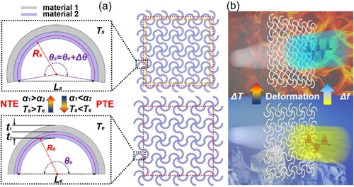
Apart from the thermal expansion property, the metasurface can exhibit a specific EM performance when either of the two constituent materials of the beams is electrically conductive, and its reflection/transmission performance can be regulated by modifying the geometric parameters of the beams. Therefore, a multifunctional metasurface can be achieved, which can realise the thermal control of EM waves based on its temperature-sensitive property using an appropriate combination of materials, as shown in (b). It should be noted that in this study, the NTE metasurface was primarily fabricated and tested because the thermal expansion performance (positive or negative) could be reversed simply by switching the positions of materials 1 and 2. The positive and near-zero thermal expansion cases were analysed theoretically and via finite element analysis (FEA) simulation, but there was no systematic practical test.
2.2. Materials and fabrication
To simplify the fabrication of metasurfaces, we chose continuous carbon-fibre reinforced PA composites (CCF/PA) and PA as the constituent materials of the bi-material beams. CCF/PA is highly conductive (σ≈3.2 × 10⁴ S/m), whereas PA is essentially an electrical insulator. In addition, the CTE of PA is significantly higher than that of CCF/PA (αPA≈106.6 × 10⁻⁶ K−1, αCCF/PA≈1.16 × 10−6 K−1). Therefore, by appropriately combining CCF/PA and PA using 4D printing, metasurfaces with both tunable EM and thermal expansion performances could be realised.
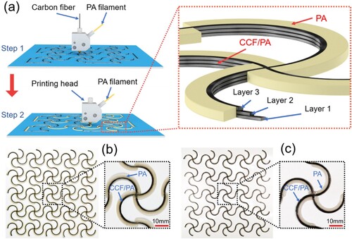
The CCF/PA material was prepared by melting and mixing PAN-based carbon fibre (1 K, T300, Toray) and PA (1.75 mm diameter, PolyMideTM CoPA, Polymaker) in a continuous fibre composite 3D printer (Combot 200, Fibertech) and extruded from the nozzle. The printer can realise switching printing of continuous fibre composites and pure resin materials using a single extrusion head with different size nozzles. Taking the printed NTE metasurface as an example, as shown in (a), the CCF/PA material was first printed using a nozzle with a diameter of 1 mm, starting from the origin, moving along the black track, and finally returning to the origin to complete the printing of layer 1. The same process was repeated to print layers 2 and 3. The thickness of each layer of the printed continuous fibre composites was 0.3 mm. The entire inner arc was first completed. The printing head was replaced using another nozzle with a diameter of 1.5 mm to print the outer material, PA, which was printed in a single step with a thickness of 0.9 mm. The nozzle also started from the origin, moved along the light-yellow track, and finally returned to the origin to complete the fabrication of the bi-material metasurface. Note that the printing temperature of both materials is 538.15 K and the printing speed is 100 mm/min. (b) shows a post-treated NTE metasurface sample, and (c) shows a PTE metasurface sample.
Figure 2. (a) Diagram of fabrication strategy of the metasurface using 4D printing of continuous carbon fibre and PA filament. (b) Image of a fabricated NTE metasurface. (c) Image of a fabricated PTE metasurface.
2.3. Thermal deformation measurement
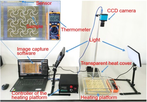
As depicted in , the sample was placed on the surface of the heating platform and covered with a transparent heat cover to reduce air convection. A heating platform controller (CHB702, Winpark) was used to set the temperature of the platform, and a temperature sensor (TP01, Yisheng Victor) was placed on the upper surface of the platform to measure the actual temperature of the copper platform surface and display it on a digital multimeter (Victor 890H+, Yisheng Victor). The sample configuration was imaged in real-time using a CCD camera. To ensure precise measurement, fill-in light was used to acquire images of the samples, which were then imported into the ImageJ 1.53 software. Measurements were performed after calibration of the size of the image according to the given scale.
Figure 3. Experiment setup to measure the thermal expansion of the metasurfaces.
2.4. EM wave transmittance test
Two horn antennas were used as ports 1 and 2 to transmit and receive EM waves, respectively. The EM wave transmission test at 4–6 GHz was performed using a vector network analyzer (Agilent N5230A). A metal plate was utilised for normalisation calibration, and the transmittance of the PLA mesh bracket was almost the same as that of air.
2.5. Finite element analysis
FEA was performed using the commercial software COMSOL Multiphysics. The calculation of the effective CTE was implemented in the solid mechanics module, and the simulation of microwave transmittance was completed in the EM wave module with a finer free triangular mesh. The floquet periodicity was selected as the boundary condition to calculate the microwave transmittance of an infinite metasurface using periodic bi-material elements.
Most of FEA material parameters were measured by instruments. The effective CTEs of PA and CCF/PA were carried out by a thermal mechanical analyzer (TMA Q400, Waters), the densities were conducted by a density balance (DX-300, Qunlong), the moduli were tested by using a universal machine (CMT4304–5 kN, SANS) and a micro ohm metre (YP2511, Yongpeng) was used to measure the electrical conductivities. It should be noted that the properties of composites are tested along the fibre direction if the parameters have anisotropy differences.
3. Results and discussion
3.1. Effect of material and structural parameters on thermal deformation
3.1.1. Width and Young’s modulus ratio of beams
Based on previous studies, when the fabrication materials for the metasurface are selected, Young’s modulus ratio of the two materials can be determined, and an optimal width ratio (Huang, Fu, and Zheng Citation2022) exists for this ratio. When the temperature increases/decreases by a certain value, the bi-material curved beam has a maximum arc angle change, which can be expressed as follows (Ni et al. Citation2019):
(3)
(3) where
and
are the width and Young’s modulus ratio of the bi-material curved beams, respectively. Lb is the arc length and Δα is the difference between the CTEs of the two materials.
Based on the selected material parameters in and the expected structural parameters in this experiment, the optimal width ratio of the structure (∼2.3) was calculated using Equation (3).
Table 1. Performance parameters of PA and CCF/PA used for calculations and simulations.
To experimentally obtain accurate values for the optimal width ratio of the bi-material curved beams, the aforementioned printing strategy was used to fabricate metasurface samples with different width ratios by adjusting the ratio of the wire feed rate relative to the printing head movement rate. Each sample was composed of a 3 × 3 array of elements, as shown in (a). We selected six uniformly distributed arcs in the horizontal and vertical directions of the metasurface and measured the total width of the bi-material arcs using a Vernier caliper. The same method was adopted to measure the widths of the composite arcs without the outer PA material, and the average value was calculated to obtain t2 (1.18 mm). Based on this value, the width ratio of the bi-material curved beams of the fabricated metasurfaces was calculated.
Figure 4. (a) Beam selection strategy to measure the width of the curved beams of the metasurface. (b) Image of the morphological difference and the measurement method for a typical sample with a designed arc radius of 15 mm, a designed arc angle of 180°, and a measured width ratio of 2.51 at 295.15 K (left) and 328.15 K (right).
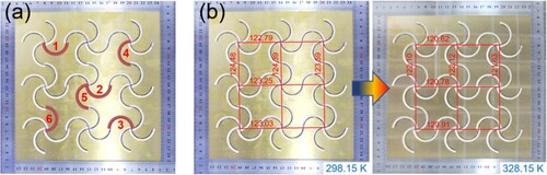
The distance of three pairs of centre points (i.e. the length of the sides of the tested metasurface) in two orthogonal directions was measured. The thermal expansion of the calibration ruler was neglected because of its much lower CTE compared to that of the sample. A metasurface is presented as an example in (b), where six measured lengths of the sides are identified in the image at temperatures of 298.15 and 328.15 K. Effective CTEs for structures with different parameters can be derived in this manner. It should be noted that the test samples were placed in the heating device for more than 10 min at an ambient temperature of 353.15 K to eliminate the internal stress of the samples produced before the test during the manufacturing process. Additionally, maintain the temperature for at least five minutes before photographing the sample at each temperature point to bring the sample's temperature as close as feasible to the measurement temperature.
Three bi-material metasurfaces with varied width ratios and the same arc radius (15 mm) and arc angle (180°) were printed for measuring the effective CTEs in the temperature ranging from 298.15 K to 358.15 K at a 10 K interval. The experimental results ((a)) collected from (b) evident that when the temperature is higher than 328.15 K, the shrinkage of the metasurface slows down for bi-material curved beams with different width ratios (see Video S1 in the Supplemental material). (c) depicts this phenomenon in greater detail. When the temperature exceeds 328.15 K, the value of effective CTE for metasurface samples with different width ratios decreases significantly. This is caused by the low Tg (glass transition temperature) of the PA material, which is approximately 338.15 ± 20 K depending on the PA type (Beaman Citation1965). Specifically, the effective CTE and the modulus of PA are significantly reduced when the temperature exceeds Tg (Jia, Spe, and Spe Citation2000), and the stress generated by the different expansions of the bi-materials is released via lateral deformation, lowering the thermal expansion modulation capability. Therefore, the temperature range for the follow-up study was set from 298.15 K to 328.15 K.
Figure 5. (a) The relationship between the length of the sides and temperature, where the slope of curves reflects the effective CTE. (b) Images of deformation of three samples with different width ratios that match Figure (a). The measurement unit is millimetres. (c) The effective CTE value at different ΔT relative to 298.15 K. Large error of CTE value of 10 K temperature difference is due to small deformation and insufficient measurement accuracy.
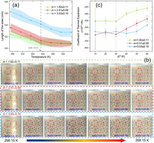
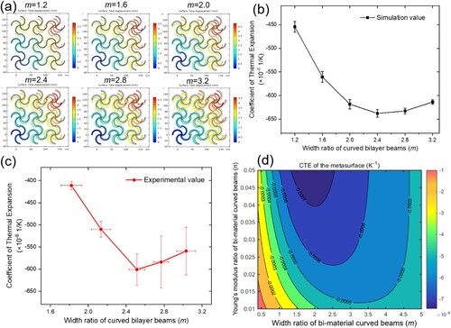
The effective CTEs of six metasurfaces with width ratios from 0.8–3.2 were calculated using FEA when the temperature was increased by 30 K. (a) shows the deformation results of these simulation model (see Video S2 in the Supplemental material for details of a typical model). The deviation interval is marked in the simulation results ((b)) in conjunction with the Poisson’s ratio fluctuations. According to the FEA results, the ideal width ratio for curved bilayer beams is in the range between 2 and 2.8. On the basis of the last experiment, two more bi-material metasurfaces with various width ratios and the same arc radius (15 mm) and arc angle (180°) were fabricated for testing the effective CTEs in the temperature range of 298.15–328.15 K. The experimental results are displayed in (c) (see Figure S3 in the Supplemental material for details). This establishes that a width ratio of approximately 2.51 is optimal for the bi-material curved beams used in this experiment. The discrepancies between the simulation and experimental results were caused by manufacturing errors in the 4D printing process and the simplification of FEA model. It was observed that after heat treatment, the actual arc radius was slightly larger than the designed parameters, and the actual arc angles were slightly reduced. This is because the material was extruded at a high temperature (∼533.15 K) during 4D printing. The NTE metasurfaces expanded outwards after deposition and cooling to room temperature (298.15 K). In addition, Young’s modulus of the PA material was affected by the temperature, and the actual modulus ratio may be smaller than that of the designed value(Jia, Spe, and Spe Citation2000). (d) shows the theoretical effective CTEs of the bi-material metasurfaces with different modulus ratios and width ratios when the arc radius and angle are fixed. It can be observed that when the modulus ratio decreases within a certain range, the optimal width ratio increases, whereas the maximum CTE decreases. This rule also exists in PTE metasurface, see Note S2 and Figure S2 in the Supplemental material. In addition, the theoretical analysis results show that when the width ratio is small enough, the effective CTE of the metasurface is close to zero. An example of near-zero expansion metasurface is demonstrated by simulation in the Supplemental material, Figure S4.
Figure 6. (a) The simulation results of six models with the different width ratios from 0.8–3.2 in COMSOL Multiphysics when temperature is increased by 30 K. The measurement unit is millimetres. (b) The simulation results of the relationship between the width ratios of the bi-material curved beams and the effective CTE. (c) The experimental results of the relationship between the width ratios of the bi-material curved beams and the effective CTE. (d) The theoretical prediction for the effective CTE of the bi-material curved metasurface related to the width ratio and Young’s modulus ratio when arc angle and radius are fixed.
3.1.2. Arc radius and angle of beams
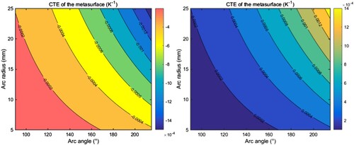
The influence of metasurface arc parameters on the effective CTE was investigated based on the optimal width ratio. Theoretically, the maximum value of the arc angle changes corresponding to the result calculated from the optimal width ratio was substituted into Equation (1), and the maximum values of the CTE corresponding to different arc angles and arc radii were obtained, as illustrated in .
Figure 7. Theoretical results and prediction of the relationship between the maximum CTE of the NTE (left) or PTE (right) metasurface and its arc angle and arc radius for the selected material combination (carbon fibre and PA).
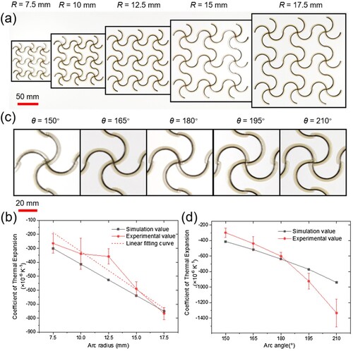
Experimentally, only the NTE metasurface was systematically analysed. The initial arc angle was set to 180°, and five metasurfaces of different sizes were fabricated with arc radii ranging from 7.5 mm to 17.5 mm at an interval of 2.5 mm ((a)). Subsequently, their effective CTE values were determined. As shown in the (b) (see Figures S5-6 in the Supplemental material for details), the experimental results are indicative of a linear relationship. The linear fitting of the results and a comparison with the simulation results show that the magnitude of the CTE of the experimental metasurface increases with an increase in the arc radius in an approximately proportional manner. To explain this phenomenon theoretically, Δθ is proportional to R0 when the arc angle θ0 is constant according to Equation (3), however, the arc radius R0 changes. It can be determined that in the variable finite space based on Equation (1), the effective CTE of the metasurface is almost proportional to the arc radius. Five different metasurface samples with arc angles ranging from 150° to 210° in intervals of 15° were also fabricated ((c)) with a constant initial arc radius of 15 mm, and their effective CTE values were evaluated based on experiments, and simulations (see Figures S7-8 in the Supplemental material for details). The test results in (d) show that the effective CTE of the metasurface improved with an increase in the arc angle. In addition, the larger the arc angle, the faster the CTE increased. The measured value of the maximum negative CTE obtained in the experiment was −1333 × 10−6 K−1, which is the largest measured value in the NTE metamaterial domain (see Video S3 in the Supplemental material for details). It should be noted that the arc angle was limited owing to the structural geometry of the metasurface.
Figure 8. (a) Metasurface samples for measurement of 5 different arc radii. (b) Simulation and measurement results of the relationship between the arc radius of the bi-material curved beams and the effective CTE. (c) Metasurface samples for measurement of 5 different arc angles. (d) Simulation and measurement results of the relationship between the arc angle of the bi-material curved metasurface and the effective CTE.
3.2. Effect of structural parameters on EM performance
3.2.1. Structural parameters before and after thermal deformation
As indicated by the experimental results, a large thermal deformation effect is ideal for regulating the EM performance of a metasurface. In this study, we focused on the tunability of the EM transmission response by introducing thermal deformation of the structure. Metasurfaces were constructed and fabricated using the same combination of materials. A sample with an arc radius of 12.5 mm and an arc angle of 180° was used as the reference metasurface. Considering the NTE characteristics of the metasurface, the transmittance of microwaves in the 4–7 GHz frequency band was simulated when the arc angles of the curved beams were 190°, 200°, and 210° as the temperature was increased. The corresponding four models are plotted in (a), and the results are shown in (b). It can be considered that with the shrinkage of NTE metasurface, the arc angle of the bi-material curved beam increases, the arc radius decreases, and the arc length is almost constant. The inset of (b) shows that as the ambient temperature increases, the curvature of the arc improves, and the −1 dB transmission band of the metasurface shifts to a higher frequency region.
Figure 9. (a) Comsol EM simulation metasurface model with four states of the corresponding increasing angle as the temperature increases. (b) The EM transmittance result of the four different states of the metasurface in the 4–7 GHz frequency region. (c) Comparison of the shape of the same metasurface in the shrinkage and expanded states. Scale bar, 20 mm. (d) The experimental setup used to measure the EM transmittance behaviour of the metasurface sample. (e) Transmittance of EM waves in the 4–6 GHz frequency band when the metasurface is in the shrinkage and expanded states.
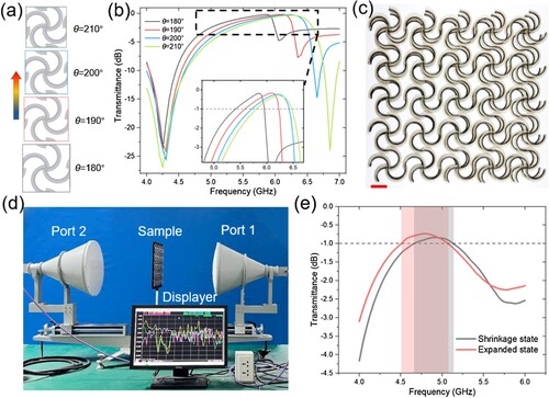
By exploiting the internal stress of the 4D-printed metasurface, two states of the same sample before and after thermal deformation can be obtained at room temperature. The cooled sample, which was taken directly from the printing platform without heat treatment, was in a shrinkage state owing to the internal stress generated by the printing process. In contrast, after heat treatment at 353.15 K for 10 min and cooling to room temperature, the sample expanded at room temperature, i.e, in an expanded state, because most of the internal stress was eliminated. As shown in (c), the two samples in different states at room temperature overlap, and they are compared. The pair of samples was designed and manufactured with an arc radius of 12.5 mm and an arc angle of 210°, and only one of them was heat-treated. The pair of samples can be regarded as being in the shrinkage state and expanded state for the same metasurface at two temperatures.
By measuring the lengths of the sides of the two metasurfaces shown in (c) and comparing the theoretical CTE values of the structures, it was concluded that the two samples can reflect the shapes of the metasurface before and after a temperature change of approximately 60 K. As shown in (d), the two samples were pasted on the surface of the PLA plastic mesh bracket, which was placed between two focusing lens horn antennas to facilitate EM measurement. The results obtained after smoothing are shown in (e). It is observed that the transmission band of −1 dB experiences a significant shift for the samples in the shrinkage and expanded states, i.e. before and after thermal deformation. When the temperature increases, the metasurface shrinks, and the −1 dB transmission band shifts from 4.5–5.07 GHz to 4.66–5.14 GHz, and the ratio of the offset to bandwidth is approximately 28.1%. Thus, regulation of EM waves with temperature change is achieved. This can be exploited in the design of novel temperature sensors and thermally controlled frequency-selective metasurfaces. It should be noted that the structural equivalence method used in this experiment does not account for how temperature affects the properties of the materials, but that any potential effect from the materials can be eliminated by material modification or replacement, which does not prevent the structural functionalization.
3.2.2. Arc radius and angle of beams
The design of metasurface structures oriented to the appropriate EM bands can be guided by the research on the impact of arc radius and angle on the performance of EM transmittance. The two samples utilised to investigate the impact of arc radius variation on the metasurface's EM transmittance performance were simulated and experimentally evaluated for their C-wave transmittance performance, as shown in (a). According to the experimental findings in (b), when the metasurface's arc angle is kept constant at 180° and the arc radius is reduced from 12.5 mm to 10 mm, the transmittance wave peak shifts from 5.44 GHz at low frequency to 6.82 GHz at high frequency. And the simulated outcomes also demonstrate the similar rise in wave peak frequency. Because the wavelength of the resonant EM wave decreases as the size of the metasurface decreases, that means the frequency of the resonant EM wave increases.
Figure 10. (a) Samples with two arc radius parameters. (b) Measured values and simulation results of EM transmittance for the two sample parts in Figure (a). (c) Samples with two arc angle parameters. (d) Measured values and simulation results of EM transmittance for the two sample parts in Figure (c).
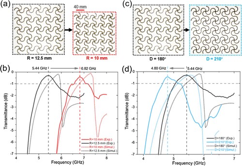
The same technique was used to test the C-wave transmission performance of the two samples utilised to examine the impact of the difference in arc angle on the EM transmittance performance of the metasurface ((c)). The experimental results in (d) show that the design size of the arc angle grows from 180° to 210° and the transmittance wave peak shifts from 5.44 GHz at high frequency to 4.8 GHz at low frequency when the arc radius of the metasurface remains constant at 12.5 mm. The manufacturing and measurement mistakes, as well as the simplification of the calculation model, are to blame for the discrepancy between the simulation findings and the actual test results, yet it also exhibits a similar pattern of change.
In addition, we also observed that the arc radius decreases and the frequency of the transmittance peak rises when the metasurface transitions from the expanded to the shrinkage state. The frequency of the transmission peak reduces at the same time that the arc angle increases, but the decrease is less dramatic than the increase. Thus, the transmission band typically shifts to high frequency as the metasurface shrinks due to thermal deformation. The findings of this study also provide an explanation for the observation that as the metasurface shrinks due to thermal deformation, the transmission band shifts from low to high frequency.
4. Conclusions
In conclusion, we designed thermally tunable metasurfaces based on bi-material chiral structures and fabricated them using continuous carbon fibre 4D printing technology. The influence of the structural and material parameters of the metasurface on the effective CTE and the influence of the metasurface’s arc parameters variation on the EM wave transmittance were investigated via theoretical analysis, FEA simulations, and experiments. By carefully treating the internal stress, we simultaneously obtained the shrinkage and expanded states of the same metasurface at room temperature. In addition, EM transmission experiments were conducted. Both the simulation and experimental results revealed that the −1 dB transmission frequency band of the shrinkage state was higher than that of the expanded state. This indicates that the metasurface can not only achieve thermal deformation under different temperature environments, but can also be utilised to adjust the transmission performance of EM waves. Also, it can be applied to various frequency bands through the design and regulation of the structural parameters. It is believed that the difference between experiment and simulation could be reduced with the development of manufacturing and instrumentation technology. Although the experiments only demonstrated the thermal deformation and EM tuning performance of the NTE metasurface, a similar response was observed for the positive or near-zero thermal expansion structure, which could broaden the application of multifunctional metasurfaces in nontraditional spaces wherein different physical parameters are coupled.
Disclosure statement
No potential conflict of interest was reported by the author(s).
Additional information
Funding
References
- Bai, Yisong, Chuanbao Liu, Yang Li, Jinxu Li, Lijie Qiao, Ji Zhou, and Yang Bai. 2022. “Programmable Mechanical Metamaterials with Tailorable Negative Poisson's Ratio and Arbitrary Thermal Expansion in Multiple Thermal Deformation Modes.” Acs Applied Materials & Interfaces 14 (31): 35905–35916. https://doi.org/10.1021/acsami.2c08270.
- Beaman, R. G. 1965. “Correlation and Prediction of Polyamide Glass Transitions.” Journal of Applied Polymer Science 9 (12): 3949–3952. https://doi.org/10.1002/app.1965.070091217.
- Chen, Y., and Q. H. He. 2020. “3D-Printed Short Carbon Fibre Reinforced Perforated Structures with Negative Poisson's Ratios: Mechanisms and Design.” Composite Structures 236. https://doi.org/10.1016/j.compstruct.2020.111859.
- Chen, Fangqi, Xiaojie Liu, Yanpei Tian, Yang Liu, and Yi Zheng. 2021. “Self-Adaptive Near-Field Radiative Thermal Modulation Using a Thermally Sensitive Bimaterial Structure.” Applied Physics Letters 119: 22. https://doi.org/10.1063/5.0073865.
- Chen, J. Y., X. J. Liu, Y. J. Tian, W. Zhu, C. Z. Yan, Y. S. Shi, L. B. Kong, H. J. Qi, and K. Zhou. 2022. “3D-Printed Anisotropic Polymer Materials for Functional Applications.” Advanced Materials 34: 5. https://doi.org/10.1002/adma.202102877.
- Fan, Xuanqing, Yuhang Li, Sihong Chen, Yufeng Xing, and Taisong Pan. 2020. “Mechanical Terahertz Modulation by Skin-Like Ultrathin Stretchable Metasurface.” Small 16: 37. https://doi.org/10.1002/smll.202002484.
- Goh, G. D., W. Toh, Y. L. Yap, T. Y. Ng, and W. Y. Yeong. 2021. “Additively Manufactured Continuous Carbon Fiber-Reinforced Thermoplastic for Topology Optimized Unmanned Aerial Vehicle Structures.” Composites Part B-Engineering 216. https://doi.org/10.1016/j.compositesb.2021.108840.
- Gu, Dongdong. 2022. “Material-Structure Integrated Additive Manufacturing: Not Simple Accumulation, But Real Integration.” In 100059. Elsevier.
- Gu, D. D., X. Y. Shi, R. Poprawe, D. L. Bourell, R. Setchi, and J. H. Zhu. 2021. “Material-Structure-Performance Integrated Laser-Metal Additive Manufacturing.” Science 372 (6545): 932-+. https://doi.org/10.1126/science.abg1487.
- Guo, J., G. Q. Xu, D. Tian, Z. G. Qu, and C. W. Qiu. 2022. “A Real-Time Self-Adaptive Thermal Metasurface.” Advanced Materials 34: 24. https://doi.org/10.1002/adma.202201093.
- Han, Z. T., X. Y. J. Xiao, J. X. Chen, K. Wei, Z. G. Wang, X. J. Yang, and D. N. Fang. 2022. “Bifunctional Metamaterials Incorporating Unusual Geminations of Poisson's Ratio and Coefficient of Thermal Expansion.” Acs Applied Materials & Interfaces 14 (44): 50068–50078. https://doi.org/10.1021/acsami.2c11702.
- Hu, Fangrong, Ningning Xu, Weiming Wang, Yue'e Wang, Wentao Zhang, Jiaguang Han, and Weili Zhang. 2016. “A Dynamically Tunable Terahertz Metamaterial Absorber Based on an Electrostatic MEMS Actuator and Electrical Dipole Resonator Array.” Journal of Micromechanics and Microengineering 26: 2. https://doi.org/10.1088/0960-1317/26/2/025006.
- Huang, Jingxiang, Minghui Fu, and Binbin Zheng. 2022. “"Elastic Mechanics Solution of Thermal Expansion of Bi-Material Curved Beam and Its Application to Negative Thermal Expansion Metamaterials.” Scientific Reports 12 (1): 11755. https://doi.org/10.1038/s41598-022-16036-2.
- Iragi, M., C. Pascual-Gonzalez, A. Esnaola, C. S. Lopes, and L. Aretxabaleta. 2019. “Ply and Interlaminar Behaviours of 3D Printed Continuous Carbon Fibre-Reinforced Thermoplastic Laminates; Effects Of Processing Conditions and Microstructure.” Additive Manufacturing 30. https://doi.org/10.1016/j.addma.2019.100884.
- Jia, N. Y., V. A. Kagan Spe, and Spe. 2000. “Mechanical Performance of Polyamides with Influence of Moisture and Temperature - Accurate Evaluation and Better Understanding.” Paper presented at the 58th Annual Technical Conference of the Society-of-Plastics-Engineers, Orlando, FL, May 07-11.
- Lakes, R. 1996. “Cellular Solid Structures with Unbounded Thermal Expansion.” Journal of Materials Science Letters 15 (6): 475–477. https://doi.org/10.1007/BF00275406.
- Lewi, T., N. A. Butakov, and J. A. Schuller. 2019. “Thermal Tuning Capabilities of Semiconductor Metasurface Resonators.” Nanophotonics 8 (2): 331–338. https://doi.org/10.1515/nanoph-2018-0178.
- Liu, Y. J., H. L. Yang, X. J. Huang, Z. T. Yu, S. R. Li, and Y. J. Yang. 2021. “A Metamaterial Polarization Converter with Half Reflection and Half Transmission Simultaneously.” Physics Letters A 389. https://doi.org/10.1016/j.physleta.2020.127101.
- Lor, C., R. Phon, M. Lee, and S. Lim. 2022. “Multi-Functional Thermal-Mechanical Anisotropic Metasurface with Shape Memory Alloy Actuators.” Materials & Design 216. https://doi.org/10.1016/j.matdes.2022.110569.
- Ma, Ruizhe, Lu Liu, Omar Wyman, and Damiano Pasini. 2022. “Programming Polymorphable yet Stiff Truss Metamaterials in Response to Temperature.” Applied Materials Today 27. https://doi.org/10.1016/j.apmt.2022.101432.
- Mizukami, K., K. Funaba, and K. Ogi. 2021. “Design and Three-Dimensional Printing of Carbon-Fiber-Composite Elastic Metamaterials with Inertial Amplification Mechanisms.” Journal of Sound and Vibration 513. https://doi.org/10.1016/j.jsv.2021.116412.
- Mizukami, K., T. Kawaguchi, K. Ogi, and Y. Koga. 2021. “Three-Dimensional Printing of Locally Resonant Carbon-Fiber Composite Metastructures for Attenuation of Broadband Vibration.” Composite Structures 255. https://doi.org/10.1016/j.compstruct.2020.112949.
- Ni, Xiaoyue, Xiaogang Guo, Jiahong Li, Yonggang Huang, Yihui Zhang, and John A. Rogers. 2019. “2D Mechanical Metamaterials with Widely Tunable Unusual Modes of Thermal Expansion.” Advanced Materials 31: 48. https://doi.org/10.1002/adma.201905405.
- Qu, Jingyuan, Muamer Kadic, Andreas Naber, and Martin Wegener. 2017. “"Micro-Structured Two-Component 3D Metamaterials with Negative Thermal-Expansion Coefficient from Positive Constituents.” Scientific Reports 7. https://doi.org/10.1038/srep40643.
- Rahmani, M., L. Xu, A. E. Miroshnichenko, A. Komar, R. Camacho-Morales, H. Chen, Y. Zarate, et al. 2017. “Reversible Thermal Tuning of All-Dielectric Metasurfaces.” Advanced Functional Materials 27 (31). https://doi.org/10.1002/adfm.201700580.
- Ren, Zhihao, Yuhua Chang, Yiming Ma, Kailing Shih, Bowei Dong, and Chengkuo Lee. 2020. “Leveraging of MEMS Technologies for Optical Metamaterials Applications.” Advanced Optical Materials 8 (3). https://doi.org/10.1002/adom.201900653.
- Saeed, K., A. McIlhagger, E. Harkin-Jones, J. Kelly, and E. Archer. 2021. “Predication of the In-Plane Mechanical Properties of Continuous Carbon Fibre Reinforced 3D Printed Polymer Composites Using Classical Laminated-Plate Theory.” Composite Structures 259. https://doi.org/10.1016/j.compstruct.2020.113226.
- Somireddy, M., and A. Czekanski. 2020. “Anisotropic Material Behavior of 3D Printed Composite Structures - Material Extrusion Additive Manufacturing.” Materials & Design 195. https://doi.org/10.1016/j.matdes.2020.108953.
- Stephen, L., N. Yogesh, and V. Subramanian. 2018. “Broadband Asymmetric Transmission of Linearly Polarized Electromagnetic Waves Based on Chiral Metamaterial.” Journal of Applied Physics 123 (3): 3. https://doi.org/10.1063/1.5008614.
- Surjadi, J. U., L. B. Gao, H. F. Du, X. Li, X. Xiong, N. X. Fang, and Y. Lu. 2019. “Mechanical Metamaterials and Their Engineering Applications.” Advanced Engineering Materials 21 (3): 3. https://doi.org/10.1002/adem.201800864.
- Tian, Xiaoyong, Akira Todoroki, Tengfei Liu, Lingling Wu, Zhanghao Hou, Masahiro Ueda, Yoshiyasu Hirano, Ryosuke Matsuzaki, Koichi Mizukami, and Keisuke Iizuka. 2022. “3d Printing of Continuous Fiber Reinforced Polymer Composites: Development, Application, and Prospective.” Chinese Journal of Mechanical Engineering: Additive Manufacturing Frontiers: 100016. https://doi.org/10.1016/j.cjmeam.2022.100016
- Tibbits, S. 2014. “4D Printing: Multi-Material Shape Change.” Architectural Design 84 (1): 116–121. https://doi.org/10.1002/ad.1710.
- Toropova, M. M., and C. A. Steeves. 2015. “Adaptive Bimaterial Lattices to Mitigate Thermal Expansion Mismatch Stresses in Satellite Structures.” Acta Astronautica 113: 132–141. https://doi.org/10.1016/j.actaastro.2015.03.022.
- Wang, K. Y., J. X. Chen, Z. T. Han, K. Wei, X. J. Yang, Z. G. Wang, and D. N. Fang. 2022. “Synergistically Program Thermal Expansional and Mechanical Performances in 3D Metamaterials: Design-Architecture-Performance.” Journal of the Mechanics and Physics of Solids 169. https://doi.org/10.1016/j.jmps.2022.105064.
- Wang, Zhonggang, Zichao Guo, Zhendong Li, and Kexin Zeng. 2023. “Design, Manufacture, and Characterisation of Hierarchical Metamaterials for Simultaneous Ultra-Broadband Sound-Absorbing and Superior Mechanical Performance.” Virtual and Physical Prototyping 18 (1): e2111585. https://doi.org/10.1080/17452759.2022.2111585
- Wang, Qiming, Julie A. Jackson, Qi Ge, Jonathan B. Hopkins, Christopher M. Spadaccini, and Nicholas X. Fang. 2016. “Lightweight Mechanical Metamaterials with Tunable Negative Thermal Expansion.” Physical Review Letters 117: 17. https://doi.org/10.1103/PhysRevLett.117.175901.
- Wang, Qingrui, Xiaoyong Tian, Lan Huang, Dichen Li, Andrei V. Malakhov, and Alexander N. Polilov. 2018. “Programmable Morphing Composites with Embedded Continuous Fibers by 4D Printing.” Materials & Design 155: 404–413. https://doi.org/10.1016/j.matdes.2018.06.027.
- Wei, K., H. S. Chen, Y. M. Pei, and D. N. Fang. 2016. “Planar Lattices with Tailorable Coefficient of Thermal Expansion and High Stiffness Based on Dual-Material Triangle Unit.” Journal of the Mechanics and Physics of Solids 86: 173–191. https://doi.org/10.1016/j.jmps.2015.10.004.
- Wei, K., Y. Peng, Z. L. Qu, Y. M. Pei, and D. N. Fang. 2018a. “A Cellular Metastructure Incorporating Coupled Negative Thermal Expansion and Negative Poisson's Ratio.” International Journal of Solids and Structures 150: 255–267. https://doi.org/10.1016/j.ijsolstr.2018.06.018.
- Wei, K., Y. Peng, K. Y. Wang, S. Y. Duan, X. J. Yang, and W. B. Wen. 2018. “Three Dimensional Lightweight Lattice Structures with Large Positive: Zero and Negative Thermal Expansion.” Composite Structures 188: 287–296. https://doi.org/10.1016/j.compstruct.2018.01.030.
- Wei, Kai, Xiaoyujie Xiao, Jiaxin Chen, Yazhuo Wu, Maojun Li, and Zhonggang Wang. 2021a. “Additively Manufactured Bi-Material Metamaterial to Program a Wide Range of Thermal Expansion.” Materials & Design 198. https://doi.org/10.1016/j.matdes.2020.109343.
- Wei, K., X. Y. J. Xiao, W. T. Xu, Z. T. Han, Y. Z. Wu, and Z. G. Wang. 2021. “Large Programmable Coefficient of Thermal Expansion in Additively Manufactured Bi-Material Mechanical Metamaterial.” Virtual and Physical Prototyping 16 (sup1): S53–S65. https://doi.org/10.1080/17452759.2021.1917295.
- Wu, Wenwang, Wenxia Hu, Guian Qian, Haitao Liao, Xiaoying Xu, and Filippo Berto. 2019. “Mechanical Design and Multifunctional Applications of Chiral Mechanical Metamaterials: A Review.” Materials & Design 180. https://doi.org/10.1016/j.matdes.2019.107950.
- Wu, Lingling, Zirui Zhai, Xinguang Zhao, Xiaoyong Tian, Dichen Li, Qianxuan Wang, and Hanqing Jiang. 2022. “Modular Design for Acoustic Metamaterials: Low-Frequency Noise Attenuation.” Advanced Functional Materials 32: 13. https://doi.org/10.1002/adfm.202105712.
- Xu, J., D. L. Jia, Y. Liu, Y. Tian, and X. M. Yu. 2020. “Tunable Terahertz Metamaterial Absorber Actuated by Thermomechanical Bimaterial Microcantilevers.” Optics Express 28 (7): 10329–10336. https://doi.org/10.1364/OE.385948.
- Xu, W. T., X. Y. J. Xiao, J. X. Chen, Z. T. Han, and K. Wei. 2022. “Program Multi-Directional Thermal Expansion in a Series of Bending Dominated Mechanical Metamaterials.” Thin-Walled Structures 174. https://doi.org/10.1016/j.tws.2022.109147.
- Yamamoto, N., E. Gdoutos, R. Toda, V. White, H. Manohara, and C. Daraio. 2014. “Thin Films with Ultra-low Thermal Expansion.” Advanced Materials 26 (19): 3076–3080. https://doi.org/10.1002/adma.201304997.
- Yin, Lixian, Xiaoyong Tian, Zhentao Shang, Xin Wang, and Zhanghao Hou. 2019. “Characterizations of Continuous Carbon Fiber-Reinforced Composites for Electromagnetic Interference Shielding Fabricated by 3D Printing.” Applied Physics a-Materials Science & Processing 125 (1): 4. https://doi.org/10.1007/s00339-018-2303-0.
- Zeng, C. J., L. W. Liu, W. F. Bian, J. S. Leng, and Y. J. Liu. 2022. “Temperature-Dependent Mechanical Response of 4D Printed Composite Lattice Structures Reinforced by Continuous Fiber.” Composite Structures 280. https://doi.org/10.1016/j.compstruct.2021.114952.
- Zeng, Y., Q. Wu, and D. H. Werner. 2010. “Electrostatic Theory for Designing Lossless Negative Permittivity Metamaterials.” Optics Letters 35 (9): 1431–1433. https://doi.org/10.1364/OL.35.001431.
- Zheludev, N. I. 2010. “The Road Ahead for Metamaterials.” Science 328 (5978): 582–583. https://doi.org/10.1126/science.1186756.