
 ?Mathematical formulae have been encoded as MathML and are displayed in this HTML version using MathJax in order to improve their display. Uncheck the box to turn MathJax off. This feature requires Javascript. Click on a formula to zoom.
ABSTRACT
One of the areas that have benefited the most from the advent of additive manufacturing is the development of customized cellular materials, scaffolds and lattices. Although these different groups of materials are typically considered separately, they can be categorized as mechanical metamaterials. Among the different additive manufacturing techniques, perhaps the most popular is that of Fused Filament Fabrication. Numerous works have been reported in the literature in which this fabrication technique has been used to produce such materials. Inspired by the increasing volume of work dealing with the subject, we present a review of the manufacturing and characterization of cellular and lattice-based mechanical metamaterials using Fused Filament Fabrication. An overview of the topologies, their effective mechanical properties and intrinsic manufacturing aspects are presented. The methods for failure analysis at different scales are also discussed. Finally, studies comparing the production of mechanical metamaterials using Fused Filament Fabrication and other additive manufacturing techniques are presented, in addition to recommendations and current trends in the production of these structures by Fused Filament Fabrication.
1. Introduction
Fused Filament Fabrication (FFF) or Fused Deposition Modelling (FDM) is one of the most widespread additive manufacturing processes (Gao, Yu, and Li Citation2020). According to the ISO/ASTM 52,900 standard (ISO/ASTM 52900:Citation2021(E) Citation2021), it falls into the category of material extrusion additive manufacturing processes (MEX).
Due to the wide availability of the FFF technology numerous works have been published in recent years, which in turn have led to reviews and overviews covering different aspects such as materials, influence of process parameters, and the mechanical characterization of FFF materials. A list of these previous reviews and their topics is presented in .
Table 1. Reviews published in the field of FFF.
FFF have had a positive impact in different fields e.g. the automotive industry (Romero et al. Citation2021), textiles (Melnikova, Ehrmann, and Finsterbusch Citation2014), biomedical products (Goswami et al. Citation2021; Buj et al. Citation2021), sound absorption (Wang et al. Citation2023; Li et al. Citation2021) and compliant mechanisms (Merriam and Howell Citation2016), among others (Ngo et al. Citation2018). Nonetheless, FFF has been a transformative force in the design and development of lattice and porous materials – recently labeled as mechanical metamaterials (MM) (Nazir et al. Citation2019; Uribe-Lam et al. Citation2021; Askari et al. Citation2020).
In recent years, advances in mechanical metamaterials have become largely intertwined with FFF and other AM processes. Their capability to produce intricate geometries and the growing interest in the development of lattice structures, for optimization or customization of mechanical properties, has resulted in numerous works published during the last few years. Employing the SCOPUS database and using the search terms ‘Mechanical AND Metamaterials’ gives out 14,587 documents (5,555 in 2021, 6,904 in 2022 and 2,128 in 2023 up-to-date). A second search now using ‘Mechanical AND Metamaterials AND Additive AND Manufacturing’ gives 3,750; almost a quarter of the results frequently use these two jointly.
The field of mechanical metamaterials, which includes architected materials (Bhate et al. Citation2019), cellular materials and lattices has also inspired several reviews that outline topologies, materials and AM technologies commonly used to produce MM (Nazir et al. Citation2019; Uribe-Lam et al. Citation2021; Kladovasilakis et al. Citation2022). Although the volume of work using FFF is significant and steadily increasing, a review focusing on mechanical metamaterials built by FFF has not been published to the knowledge of the authors. These reviews have focused on the advantages and disadvantages of AM methods but have not delved deeper into any particular AM technology. Because each method possesses different capabilities and constraints, we consider that a more focused review centered on FFF is necessary.
Although FFF is commonly considered as a good fit for prototyping and low-volume production it has several traits that make it a good option in manufacturing. In comparison to other AM technologies such as stereolithography (SLA) or selective laser sintering (SLS), FFF is not just cost-effective, but also eliminates the challenges and risks associated to the use of resins or powder. FFF is capable of printing diverse materials, including thermoplastics, elastomers, and combinations of different materials that include fiber and particle reinforced polymers. Even if resolution and accuracy are inferior to those of other AM processes, it can produce parts of good quality, as well as complex self-supporting geometries, with mechanical properties comparable to those of SLS and SLA parts.
These traits have resulted in the widespread use of FFF for the development of MM in recent years Hence, it is necessary to examine the state-of-the-art in the field, while reflecting on the capabilities, limitations, best practices and current trends for the use of FFF in the field of mechanical metamaterials.
This review is structured as follows: in Section 2 we assess the topologies commonly fabricated; Section 3 discusses best practices and recommendations for FFF of mechanical metamaterials; studies focused on the characterization and mechanical properties are summarized in Section 4; methods for the analysis of the deformation and failure mechanisms in mechanical metamaterials are presented in Section 5. Section 6 is dedicated to comparing FFF and other AM methods in the production of lattices. Finally, Section 7 discusses the limitations of earlier studies and future perspectives in the area.
2. Cellular topologies commonly fabricated via FFF
Infill patterns that are commonly used in FFF to add internal support and reduce use of material and printing time can be classified as cellular or lattice materials. We begin our review by analyzing some of the most used infill topologies and their corresponding mechanical properties. Then, the discussion moves to customized porous structures built by FFF. These are separated into 2D structures or honeycombs (in-plane porosity), and 3D structures (with porosity in multiple planes).
2.1 Infill topologies
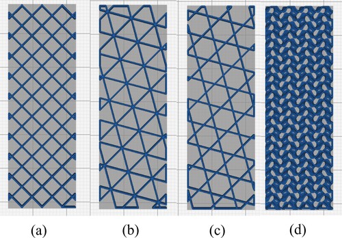
Numerous works have studied how manufacturing (e.g. extrusion temperature and velocity) and structural (number of layers, orientation and infill percentage and/or pattern) parameters affect the mechanical properties of FFF parts (Cuan-Urquizo et al. Citation2019). The user can select the infill topology among a range of options directly in the slicing software. Some of the most common infill patterns are square (also known as grid), hexagonal, triangular, and Kagome (also known as tri-hexagon). Some of these are depicted in a–c. More recently, some slicing software has incorporated 3D surface-based infills, such as gyroid (d). Although some infill patterns are common to all AM software, the availability is subject to the software and its version. Parameter settings vary considerably from one slicer software to other: Some slicer software enable the adjustment of different parameters like infill line width, distance, layer thickness; on the other hand, others limit parameters to just infill percentage or use some other parameter entirely.
Figure 1. Some of the commonly used infills: (a) square or grid, (b) triangular, (c) Kagome, and (d) gyroid. All were generated in CURA® (Ultimaker BV, Netherlands) with a 20% infill density.
2.2 Cellular and porous topologies
Regular mechanical metamaterials (or lattices) can be formed from the repetition of a representative volume, also known as the unit cell. The topologies of cellular structures commonly built by FFF are reviewed in the upcoming sections.
2.2.1 Honeycombs (in-plane porosity)
This section covers those topologies that are created intentionally, and not as an infill pattern. Honeycombs are relatively easy to build from the stacking of extruded layers in the out-of-plane direction. The most common 2D topologies fabricated with FFF reported in the literature are summarized in .
Figure 2. 2D honeycombs (a) hexagonal, (b) re-entrant, (c) arrow head, (d) tetra a-chiral, (e) tetra chiral, (f) hound tooth’s and (g)-(h) re-entrant variations proposed by Ingrole et al. (Citation2017).
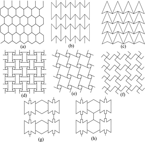
Among 2D structures, the hexagonal honeycomb has been studied extensively (Basurto-Vázquez et al. Citation2021; Sang et al. Citation2019; Goodarzi Hosseinabadi et al. Citation2017; Sharma et al. Citation2020; Lam et al. Citation2019; Bates, Farrow, and Trask Citation2019; Hedayati et al. Citation2016; Mansour, Tsongas, and Tzetzis Citation2021) (a). A variant of the hexagonal honeycomb is formed after inverting the sign of the angles between the vertical (or horizontal) elements, resulting in auxetic properties, i.e. they exhibit negative Poisson’s ratio (Ren et al. Citation2018). This structure is called re-entrant and has also been built and studied using FFF (Vyavahare and Kumar Citation2020; Vyavahare, Teraiya, and Kumar Citation2021b; Vyavahare and Kumar Citation2021) (b). Other 2D auxetic structures have also been fabricated via FFF, for example, that formed from the periodic arrangement of arrowheads (Yang, Vora, and Chang Citation2018; Usta, Türkmen, and Scarpa Citation2021) (c). Hybrid or combinations of different 2D topologies are also reported, for example, in the work of Ingrole et al. (Citation2017), where the combination of hexagonal and re-entrant structures was proposed.
Chiral and a-chiral lattices, some of which also exhibit auxetic properties (Wu et al. Citation2019), have also been found in the literature (Kumar et al. Citation2021; Gunaydin et al. Citation2021; Auricchio et al. Citation2019; Scarpa et al. Citation2007; Lorato et al. Citation2010; Hu et al. Citation2020). Chiral-type structures are formed from the combination of nodes (circular shapes) and ribs (or ligaments), see d and e. Other variations of 2D arrangements were also reported, such as the one that resembles the hound tooth pattern (Shepherd et al. Citation2020). This pattern consists of the zig zag-type orthogonally alternating strands as shown in f. Other chiral-type variations result in a triangular-auxetic structure reported in (Jafari Nedoushan et al. Citation2021).
One novel approach to the design of 2D lattice structures is through the combination of multiple polymers inside one structure. This is possible in FFF multi-nozzle devices that enable the fabrication of multimaterial metamaterials (Wei et al. Citation2021), removing the need for additional joining processes (Wei et al. Citation2021). This method can even be extended for the production of honeycomb structures (Han et al. Citation2023).
AM enables precise control of pore size, shape, and relative density (Duraibabu et al. Citation2020), opening the possibility of creating structures with varying mechanical properties in different regions, i.e. Functionally Graded Cellular Structures (FGCS). The production of FGCS via FFF has been explored for different honeycomb structures in (Bates, Farrow, and Trask Citation2019; Ufodike et al. Citation2021; Nian et al. Citation2019).
Alternatively, 2D bioinspired structures have also been proposed. For instance, Sharma and Hiremath (Sharma and Hiremath Citation2022) proposed a cellular material derived from a marine sponge consisting of regular square honeycombs with vertical and horizontal struts, reporting its energy absorption and deformation behavior under quasi-static and cyclic loading. Ufodike et al. (Citation2021) proposed a novel cellular structure, a functionally graded honeycomb based on the microstructure of bamboo, and built it using FFF. Similarly, Bru et al. (Citation2020) proposed two new honeycomb cores inspired by the microarchitecture of enamel and bamboo vascular bundles. A comprehensive list of 2D topologies studied in the literature is presented in .
Table 2. Summary of studies reporting on the mechanical characterization via compression tests on 2D structures or honeycombs.
2.2.2 Strut-based 3D lattice structures
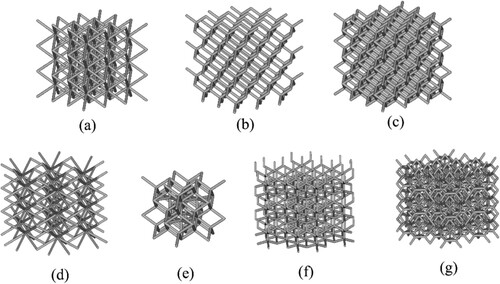
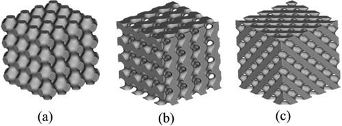
During the last few years, an increasing number of 3D truss-like lattices fit for FFF have been identified, manufactured and tested. Among the different topologies, those based on body-centered cubic (BCC) unit cells were the most common (Ravari MR et al. Citation2014; Abdulhadi and Mian Citation2019; Al Rifaie, Mian, and Srinivasan Citation2019; Azmi et al. Citation2018; Fadeel et al. Citation2019; Fadeel et al. Citation2022; Jhou, Hsu, and Yeh Citation2021; Momeni, Mofidian, and Bardaweel Citation2019; Rezaei et al. Citation2017) (a), yet lattice topologies based on variants of the cubic unit cell have been fabricated as well (Abusabir et al. Citation2022; Gorguluarslan et al. Citation2015; Gorguluarslan et al. Citation2016; Matlack et al. Citation2016; Monteiro et al. Citation2021; Wen and Li Citation2021; Dong et al. Citation2018). Other unit cell types based on polyhedra and other geometric figures have been manufactured and analyzed, including the Kagome truss (Gautam, Idapalapati, and Feih Citation2018), octet (Momeni, Mofidian, and Bardaweel Citation2019; Gorguluarslan et al. Citation2016; Emir, Bahçe, and Uysal Citation2021; Intrigila, Nodargi, and Bisegna Citation2022; Kaur et al. Citation2017; Sun, Guo, and Shim Citation2021; Sun, Guo, and Shim Citation2021; Sun, Guo, and Shim Citation2022), octahedral (Kaur et al. Citation2017), Kelvin cell (Ge et al. Citation2018; Guerra Silva, Torres, and Zahr Viñuela Citation2021; Rossiter, Johnson, and Bingham Citation2020), rhombic dodecahedron (Sun, Guo, and Shim Citation2021; Sun, Guo, and Shim Citation2021; Sun, Guo, and Shim Citation2022), sphere (Tang et al. Citation2020), and diamond (Intrigila, Nodargi, and Bisegna Citation2022; Guerra Silva et al. Citation2021; Guerra Silva et al. Citation2021; Guerra Silva et al. Citation2021) (b), among many others (Wen and Li Citation2021; Chun and Kowalik Citation2018; Khare et al. Citation2018; Lvov et al. Citation2020; Valle et al. Citation2022; Guerra Silva et al. Citation2021a, Citation2021b) (c–g).
Figure 3. Some of the 3D lattice structures that have been fabricated using FFF: (a) BCC or cube vertex centroid, (b) cubic diamond, (c) tet vertex centroid, (d) hex prism vertex, (e) tet oct vertex centroid, (f) hex prism diamond, (g) hex prism laves phase. Models generated using nTopology® (nTopology Inc., USA).
3D lattices based on atomic structures have also been reproduced at larger scales using additive manufacturing to analyze their mechanical response, offering an innovative approach for the evaluation of microscopic structures. For instance, Gaal et al. (Citation2021) and Felix et al. (Citation2020) evaluated a triply periodic minimal surface (TPMS) topology named schwarzite, showing a strong correlation between the stress–strain curves of 3D printed models and the ones obtained from molecular dynamics models, reporting scale-size invariance and the observed deformation mechanisms (more details on TPMS are given in its corresponding section). Ambekar et al. (Citation2021) successfully 3D printed zeolite-templated carbon nanotube networks based on macro models generated from atomic models (). Sajadi et al (Citation2019) worked on 3D printed tubulanes – analogs of cross-linked carbon nanotubes – highlighting the potential of 3D printed geometries inspired by atomic and nanoscale models. An exhaustive list of 3D unit cell types and topologies studied in the literature is presented in .
Figure 4. 3D printed zeolite-inspired structures, with permission from Elsevier (Ambekar et al. Citation2021).
Table 3. Summary of studies focused on the mechanical characterization via compression tests on 3D structures.
2.2.3 Woodpile arrangement: structure formed from the stack of extruded rasters
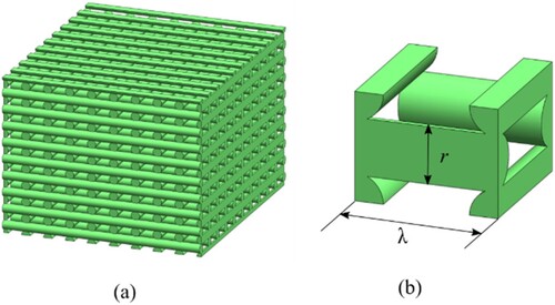
Structures consisting of the orthogonal stacking of extruded raster are formed easily due to the characteristics of the FFF process. This stack of rasters resembles that encountered in piles of wooden logs; hence it is also known as woodpile structure. This arrangement and its corresponding unit cell are depicted in a and b, respectively. The volume fraction of the woodpile structure is a function of the distance between rasters (λ) and the radius (r). Note that the stacking sequences that include the arrangement of rasters (represented as cylinders) result in porosity in the three orthogonal planes. Numerous works have explored the use of this material arrangement as tissue engineering scaffolds (Zein et al. Citation2002; Hutmacher et al. Citation2001; Baptista and Guedes Citation2019; Gregor et al. Citation2017; Ruiz-Cantu et al. Citation2016). The area of biomedical tissue engineering scaffolds is extensive and beyond the scope of the review, thus the reader is referred to (Wen et al. Citation2017; Zhang et al. Citation2019).
Figure 5. (a) Woodpile structure and its corresponding (b) unit cell.
2.2.4 Surface-based porous structures for metamaterials
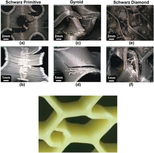
Triply Periodic Minimal Surface structures. Different triply periodic minimal surfaces (TPMS) have also been fabricated via FFF. These structures can be found as surface-based and strut-based (known in the literature as skeletal (Kladovasilakis et al. Citation2021)). Among the structures that have been reported, the ones that are more frequently encountered are the so-called schwarzites (named after Hermann Schwarz (Mackay and Terrones Citation1991; Terrones and Mackay Citation1992)), specifically: Schwarz-primitive (a), gyroid (b), and Schwarz-diamond (c) (Gaal et al. Citation2021; Felix et al. Citation2020; Kladovasilakis, Tsongas, and Tzetzis Citation2021; Sajadi et al. Citation2018; Mishra, Chavan, and Kumar Citation2021; Maconachie et al. Citation2020; Kladovasilakis et al. Citation2021; de Aquino, Maskery, and Longhitano Citation2020; Alizadeh-Osgouei et al. Citation2021). These geometries can be built from trigonometric expressions, as reported in (Kladovasilakis, Tsongas, and Tzetzis Citation2021).
Figure 6. Some of the Triply Periodic Minimal Surface structures fabricated using FFF: (a) Schwarz-primitive, (b) gyroid, and (c) Schwarz-diamond. Models generated using nTopology®.
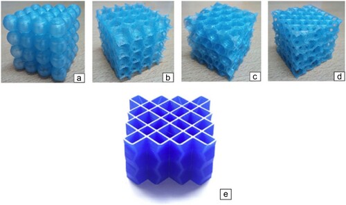
Other surface-based structures. Ben Ali et al. (Citation2019) studied porous structures formed from the arrangement of spheres. Different arrangements were explored, including two different stacking sequences: square (a and b) and hexagonal (c and d). Two different types of porosity were fabricated; (i) porosity shared between adjacent spheres, i.e. open porosity (b and d) and (ii) that which is only given by the porosity within each sphere (closed porosity) (a and c). Townsend et al. (Citation2020) proposed origami-based designs for honeycombs, consisting of square tubes with folded walls in the printing direction, i.e. inclined out of the printing plane (e). Another structure based on a closed-cell Kelvin cell was built and studied in (Duan et al. Citation2019). Additionally, novel curved-surface-based structures were recently proposed by El Jai et al. (Citation2021). A summary of surface-based 3D unit cell types and topologies (including TPMS structures) is presented in .
Figure 7. Designs fabricated by Ben Ali et al., with permission from Elsevier (Ben Ali et al. Citation2019) (top) and Townsend et al. (Citation2020) (bottom). Figures adapted from (Ben Ali et al. Citation2019; Townsend et al. Citation2020).
3. Manufacturing considerations and recommendations for FFF porous structures and metamaterials
3.1 Strut and cell wall composition
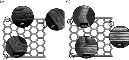
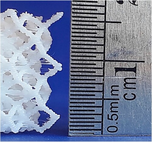
One of the main issues to consider when fabricating cellular metamaterials via extrusion techniques is how the struts or cell walls are formed. For 2D structures fabricated with pores perpendicular to the printing platform, walls are formed layer by layer, from multiple rasters deposited side by side along the length of the cell wall (see a) (Basurto-Vázquez et al. Citation2021; Lam et al. Citation2019). Because the cell wall thickness is dependent on the thickness of rasters, its design should consider the extruder diameter to ensure a successful manufacturing.
Figure 8. Honeycomb cell walls formed from multiple rasters with the main plane built (a) in the printing plane and (b) out of the printing plane, reported Basurto-Vázquez et al. (adapted from (Basurto-Vázquez et al. Citation2021)). Scale bar shown in figures corresponds to 500 micrometers.
Alternatively, a cell wall thickness could be formed from the combination of rasters deposited as inner/outer surfaces plus infill patterns in structures with thick cell walls (Sharma et al. Citation2020). This was exposed in the functionally graded structures fabricated by Bates et al. (Citation2019), in which regions of greater density required thicker walls. Other defects in FFF gyroids were reported in (Maconachie et al. Citation2020), which include misrepresented edges, and internal porosity impossible to be filled due to size limitations in the filament deposition process.
When the pores are not perpendicular to the printing plane, the cell walls will be composed of a stacking of shorter rasters, in which the length is limited by the thickness of the structure at the location (see b). Forming the 2D structures with the porosity out of the printing plane demands struts that are either aligned to the stacking axis or inclined at a certain angle from it. These out-of-plane struts will inevitably result in a clear staircase effect throughout their length, which might lead to failure (Kladovasilakis et al. Citation2021; Citation2021), as will be discussed in Section 5.
Although the staircase effect could be minimized if the structures are reoriented in the printing platform to avoid overhangs, this cannot be avoided in most 3D structures or those with inclined out-of-plane elements (). All these structures have out-of-the-printing plane struts. Deviations in 3D strut-based lattices such as staircase effect and thickness variation were reported by Guerra Silva et al. (Citation2021) and are shown in .
Figure 9. Staircase effect encountered in struts of 3D lattices, reported by Guerra Silva et al. (Figure from (Guerra Silva et al. 2021)).
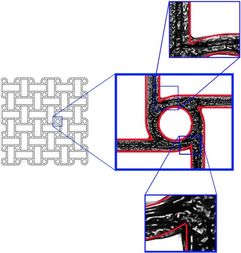
Due to the nature of FFF, sharp corners are practically impossible to build. Many honeycombs have these geometric features in their design. Hence, being aware of the fabrication limitations of FFF is critical. For example, shows a tetra a-chiral structure fabricated in TPU using a commercial FFF-printer. The red contours represent the intended geometry, which overlaps the effective geometry obtained; sharp corner radius is missing in the printed sample. Such defects will invariably affect the response of the unit cells and, subsequently, the resulting mechanical properties.
Figure 10. Geometry lost due to the limitations of the extrusion process. Tetra a-chiral honeycomb fabricated using TPU (black). The intended geometry is shown in red. (Courtesy of Pérez-Castillo).
3.2 The use of supports in the fabrication of metamaterials via FFF
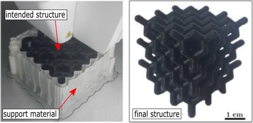
In many AM technologies, printing parts with overhangs is challenging, sometimes requiring the use of additional material labeled as support. Supports are polymer parts printed concurrently with the structure, that provide support to layers that would be otherwise deposited on the void (Germain et al. Citation2018). In FFF support structures are required when overhanging and down-facing surfaces are present (Dong et al. Citation2018; Kumar et al. Citation2020). In the fabrication of MM, this is not the exception. In FFF, support can be built using a secondary material or the same material (Kumar, Verma, and Jeng Citation2020); they can be removed either by a mechanical or chemical processes.
While the subject of support material has been extensively addressed for general FFF applications, it has been only addressed in the production of lattices in a limited fashion (Leary et al. Citation2014; Langelaar Citation2016). In-plane 2D structures or honeycombs built by FFF require little to no support, as each deposited layer serves as support for the next (Kumar, Verma, and Jeng Citation2020; Beloshenko et al. Citation2021). On the contrary, 3D cellular structures – based on trusses or walls – might require support structures, as some of the elements of the lattice are out-of-plane or inclined (Uribe-Lam et al. Citation2021).
Chemical removal of supports is the most advantageous method when manufacturing MM. Al Rifaie et al. (Al Rifaie, Mian, and Srinivasan Citation2019) reported the use of support material for the fabrication of BCC lattice structures, which was later eliminated via a heated chemical bath. Similarly, Matlack et al. (Citation2016) fabricated a lattice structure based on the cubic unit cell using support of a different material. However, no further detail was provided regarding the manufacturing process or support removal. Gautam et al. (Citation2018) used polymethyl methacrylate as support material in the production of large single Kagome cells, which was later dissolved in hot detergent water. Germain et al. (Citation2018) printed gyroid scaffolds in PLA, using either high-impact polystyrene (HIPS) or water-soluble polyvinyl alcohol (PVA) as support material. The supporting polymer was later dissolved in limonene or water, respectively, submerging the parts for several hours. The authors also compared supported and non-supported gyroid structures and reported that the support improved the printing accuracy/quality, even though the structure could be printed without support (see Section 3.1). Similarly, Intrigila et al. (Citation2022) used PVA support for the fabrication of diamond lattices ().
Figure 11. Fabrication of diamond lattice structures using PVA as support material. Specimen after removal of supports is shown to the right. Adapted from (Intrigila, Nodargi, and Bisegna Citation2022).
Mechanical removal of support structures is challenging and might lead to poor surface quality or defective parts. Furthermore, eliminating the base and support might damage the part (Thompson et al. Citation2016). Because it is especially unpractical in structures with large cross-sections, supports of dissolvable materials are the best alternative. However, removing the support by either method from lattices is arduous due to their intricate geometry (Kumar, Verma, and Jeng Citation2020). Additionally, supports require extra material, time, and energy (Kumar et al. Citation2020; Citation2020; Gaynor and Guest Citation2016), and closed lattice structures do not allow support material removal in post-processing without damaging or altering the structure. For all these reasons, the design or identification of functional self-supporting 3D lattice structures (that can be built without any support) for production via FFF could be very advantageous.
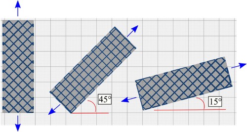
Tang et al. (Citation2018) experimented with the 3D printing of horizontal and nonhorizontal struts, varying the length (from 10 to 60 mm) and diameter (from 1 to 5 mm), and inclination in nonhorizontal struts with respect to the printing plane (from 10° to 90°, i.e. vertical) to assess the feasibility of self-supporting struts. Form deviation was larger in longer and thinner struts regardless of strut orientation. In inclined struts, a more horizontal strut led to larger deviations, especially when the angle decreased below 10°. Similarly, Rezaei et al. (Citation2017) developed two geometric benchmarks to evaluate the manufacturability of thin vertical and inclined struts without support. The first test consisted of six columns whose diameter ranged from 1 to 3 mm. The minimum feasible diameter was 1.5 mm. In the second test four columns (struts) with different angles (35, 40, 45, and 50°) with a 1.5 mm diameter were printed. The minimum angle with an acceptable quality was 40°. On the other hand, Guerra Silva et al. (Citation2021) reported a minimum strut thickness of about 0.9 mm when building self-supporting struts using a 0.4 mm nozzle. Matlack et al. (Citation2016) reported a strut thickness of 0.55 mm in vertical struts using soluble support material during the manufacturing process. No clear restrictions on the lower or upper limit of cell size have been established, but it has ranged from 3 mm to 25 mm, with strut thickness varying between 1 and 4 mm.
Rossiter et al. (Citation2020) and Guerra Silva et al. (Citation2021) reported on the manufacturing of self-supporting truncated octahedrons via FFF. Additionally, Guerra Silva et al. (Citation2021) explored the capabilities of FFF to produce self-supporting 3D strut-based miniature lattices, identifying multiple self-supporting lattice structures that can be produced by this process, and reporting that strut thickness, length and orientation were critical parameters for the production of self-supporting lattice structures.
Self-supporting surface-based lattices built by FFF have also been investigated. Beloshenko and co-workers (Citation2021) reported gyroid architectures as self-supporting due to the small size of the open area and the bridging during FFF. Other authors (Maconachie et al. Citation2020; Germain et al. Citation2018; Maharjan et al. Citation2018; Seharing, Azman, and Abdullah Citation2020) also reported on the fabrication of gyroid lattices without the use of support structures, and Ben Ali et al. (Citation2019) built lattices with a different arrangement of sphere-based unit cells without support. Additionally, Kumar et al. (Citation2020) evaluated the fabrication of both open and closed-cell lattices using FFF without support structures. Excluding the typical features (such as the staircase effect) described in Section 3.1, no imperfections were reported.
Although the use of supports in the manufacturing of 3D lattices via FFF could partly improve their accuracy, it does not eliminate common features in FFF built structures such as non-uniform strut cross-sections or lost accuracy. Furthermore, the extra steps required to remove the supports make the process less efficient and impractical. Hence, focus should be placed in the development of supportless unit-cells that reduce post-processing and can still provide functional structures.
One alternative to the limitations of conventional FFF is the use of AM equipment with a larger number of degrees of freedom, which enable material deposition from multiple directions, therefore eliminating the need for support (Thompson et al. Citation2016). Such a system has already been proposed by Bin and Larochelle (Citation2019), who integrated a six-degrees-of-freedom robot arm with a head extruder, creating a FFF multi-plane system deposition capable of producing multidirectional self-supporting 3D lattice structures.
4. Effective mechanical properties of cellular metamaterials fabricated via FFF
4.1 Effect of infill patterns on the effective mechanical properties of FFF-structures
The effective mechanical properties of MM using infill pattern are determined by both its topology and density (Cuan-Urquizo et al. Citation2019). Such impact has been characterized mainly via tensile tests, with fewer reports on compressive (Yadav, Sahai, and Sharma Citation2021) or fatigue behavior (Travieso-Rodriguez et al. Citation2020; Gomez-Gras et al. Citation2018). However, works reporting the mechanical properties of infill patterns, orientation or density have not analyzed them considering the mechanics of porous materials; concepts like rotation symmetry or deformation mechanisms that give insight into their behavior have not been explored.
Furthermore, most of the works have used samples with contour rasters (outer walls), which means that the response measured is not solely that of the infill. The contour raster contributes to the overall strength of the AM part. Therefore, the contribution of the infill lattice is just a fraction of the total strength. In some quasi-static cases (Yadav, Sahai, and Sharma Citation2021; Akhoundi and Behravesh Citation2019; Ma et al. Citation2020), the influence of the infill pattern topology on the strength and stiffness is almost indistinguishable, as all the samples were fabricated with contour rasters, even if the only parameter that changed was the infill density. The effect of contour rasters was further studied by An et al. (Citation2021), who showed that removing the contour raster resulted in an increment in the maximum elongation attained in bending-dominated infill patterns.
The effect of infill density and pattern on the tensile response of the triangular and hexagonal infill patterns in polyamide-based composites was reported by Wang et al. (Citation2020). In general, triangular infill was stiffer than the hexagonal, but the hexagonal had higher values of strength. For both topologies, their stiffness and strength exhibited non-linear increments when the infill density increased. On the contrary, elongation decreased as the density increased. The maximum values obtained for Young's modulus and tensile strength were obtained at a density of 49%; 160 MPa and 4.5 MPa, respectively, for the triangular infill; for the hexagonal infill, 98 MPa for Young's modulus and 4.7 MPa for tensile strength.
The mechanical properties of infill patterns and their directional dependency are better understood when considering the effect of rotational symmetry. Take for instance the infill pattern shown in , showing a top view of the printing bed. Depending on the part orientation on the printing bed, the infill pattern resembles a square or a diamond lattice, both having different in-plane properties. Bonada et al. (Citation2021) reported that PLA samples printed with infills containing 0-90° rasters had 30% higher stiffness than those with 45°/−45°rasters in tensile tests.
Figure 12. Influence on in-plane orientation. All were generated in CURA® with a 20% infill density.
The effect of raster orientation with respect to the principal axis of the samples on the stiffness and strength was further studied by (An, Kim, and Lee Citation2021). The square lattice, often used as infill, is more rigid when the lattice elements are aligned with the principal axis (parallel to the loading direction). It becomes more flexible when these are off by 45° with respect to the principal axis.
4.2 Experimental characterization of the effective mechanical properties
In this section we examine experimental work focused on the characterization of mechanical properties of MM built by FFF. Quasi-static compressive testing has been the focal point in most studies, although tension and bending were also investigated. First, we discuss quasi-static compressive testing of 2D structures and the few works that have explored tensile behavior. Then, we present studies dealing with compressive testing of materials based on 3D unit cell arrangements. Finally, we consider those studies exploring the flexural and dynamic response of mechanical metamaterials.
The mechanical properties of MM can be expressed using apparent or effective properties when the macro dimensions are significantly larger than the constituent elements that compose the lattice or cellular structure. Using this approach MM are analyzed as equivalent homogenous solids, in which voids (or the topology) are not considered. In general, an effective property can be expressed as
, where P is the property of the material that the cellular structure is made of, and C and n are constants related to the topology and deformation mechanisms (Gibson and Ashby Citation1982). C is a dimensionless constant that includes geometrical and topological aspects of the corresponding cellular structure, and n defines the scaling law. For instance, the hexagonal honeycomb has a constant
and n = 3 (Gibson and Ashby Citation1982).
4.2.1 Mechanical characterization of honeycombs: compression
In general, the stress–strain curve of porous media under in-plane compression exhibits three regions: linear-elastic, plateau and densification (Ashby Citation1983). The deformation mechanism, either in bending- or stretch-dominated structures, determines the initial elastic response (Deshpande, Ashby, and Fleck Citation2001). Then, porous structures strain at approximately constant stress, in the region known as the plateau stress region. This depends on the type of base material, but also the collapse mechanisms inside the structure. Finally, the collapsed constituent elements get into contact with each other, and structures become stiffer; this final stage is known as densification. Structures with 2D porosity could be characterized under compression in two different directions, i.e. in-plane and out-of-plane.
The in-plane compression of honeycomb cellular structures has been extensively studied, revealing several key factors in the apparent mechanical properties. Properties commonly reported for this loading scenario include effective Young’s modulus, strength, energy absorbed and the specific energy absorbed (SEA).
Compression tests have been used to analyze the deformation mechanisms in honeycombs. For instance, the well-known bending-dominated response of hexagonal honeycombs was reported by Sharma et al. (Sharma et al. Citation2020). Bending-dominated materials exhibit a non-linear relation between the apparent Young’s modulus and the relative density, as reported by Hedayati et al. (Citation2016). This was used to develop analytical models based on beams under flexure. An upgraded analytical model for the effective Young’s modulus of hexagonal honeycombs was derived in (Hedayati et al. Citation2016). The high-order model incorporated the shear effect in the bending response of the cell walls, improving models previously proposed in (Gibson and Ashby Citation1982), and allowing the estimation of the elastic properties of highly dense honeycombs. The high-order model is derived based on Timoshenko beam theory which is grounded on the assumption that normal cross-sections do not remain normal under flexure, as was assumed in Euler-Bernoulli theory.
An in-depth study of the strain rate sensitivity of hexagonal honeycombs fabricated via different additive technologies was presented by Lam et al. (Citation2019). Hexagonal honeycombs were built in ABS by FFF, and it was determined that the strain rate influenced both stiffness and strength, being the effect on the latter more evident. The results presented in (Lam et al. Citation2019) suggest that in order to achieve accurate predictive models, modeling-rate-dependent behavior has to be incorporated into the computations. Additionally, strain rate sensitivity could differ for different cellular topologies as this is related to the strain distribution at the cell wall (or strut) level. The effect of the printing orientation on the overall stress–strain response was exposed by (Basurto-Vázquez et al. Citation2021). For example, despite being fabricated with the same base material, and having the same honeycomb topology, those that were printed with the topology plane parallel to the printing plane exhibited a plateau region. Other orientations exhibited failure after reaching the maximum load capacity.
The orientation of the cell walls or struts within the cellular structure not only impacts the deformation mechanism but also might contribute to generating non-conventional properties such as a negative Poisson’s ratio.
Vyavahare and Kumar (Citation2021) studied the compressive response of ABS and PLA re-entrant structures. In general, as the length of the inclined members increases, both stiffness and strength are reduced, but the SEA increases. Vyavahare et al. (Citation2021a) also demonstrated that a minimal variation in volume fraction (∼±10%), improved the mechanical response, up to ∼6 times stronger, about twice stiffer and with double the SEA capacity. The manufacturing parameters that have a stronger influence on the compressive strength are the layer thickness and raster angle, while the raster angle and the number of contour rasters influenced stiffness the most (Vyavahare and Kumar Citation2020).
Other design variations to the re-entrant honeycomb were proposed by Ingrole et al. (Citation2017) (g and h). The variations presented in (Ingrole, Hao, and Liang Citation2017) had a lower elastic response (about 50% lower in the most extreme cases) when compared to their hexagonal and re-entrant counterparts. On the contrary, the variation in strength for geometries shown in g and h resulted to be roughly 75% and 38% higher than those reported for the hexagonal honeycomb. Energy absorption values showed no apparent difference. Gunaydin et al. (Citation2019) modified the re-entrant structure by thickening the vertical cell walls. The compressive response of such variation was compared with that of the anti-tetrachiral, both made of ABS, in (Gunaydin et al. Citation2019). Anti-tetrachiral structures absorbed more energy due to their collapse deformation mechanism in straight struts (ligaments) bending and rotation of the circular elements. When aiming to predict the local and overall buckling via numerical simulations, authors attributed the differences to the anisotropy and imperfections caused by FFF (Gunaydin et al. Citation2019).
Another current trend is the design of structures with zero Poisson’s ratio. For instance, Hamzehei et al. (Hamzehei et al. Citation2022) built TPU lattices with a topology inspired by the DNA molecule and subjected them to compression. Then functionally graded cell walls were also incorporated, leading to enhancements of the energy absorption capacity of up to 33% when compared to the uniform thickness lattices.
Fewer publications have dealt with the out-of-plane properties of FFF honeycombs, also known as flatwise compression. The deformation mechanism in these structures under compression is the buckling of the cell walls, as reported by Scarpa et al. (Citation2007) who characterized the out-of-plane of hexagonal chiral structures. Lorato et al. (Citation2010) studied chiral-type ABS structures subjected to out-of-plane compression. In general, the compressive modulus increases as the number of ligaments grows. This could be attributed to the fact that a higher number of ligaments result in a higher cross-section area on which the load is applied.
Typically, the samples in compressive tests are rectangular or quasi-rectangular, but some researchers have used other geometries. For instance, Tabacu and Ducu (Citation2018) used cylindrical samples in out-of-plane compression testing. The samples – filled with square lattice – were printed with their principal axis parallel to the stacking direction. Most samples showed a collapse mode as axial crushing. Further analysis of the failure mechanisms in MM is presented in Section 5.
Among the different geometries, the hexagonal honeycomb is the most common, with almost half of the studies in including some variants. The hex honeycomb is of great significance in the literature, with an extensive background in analytical modeling and engineering applications (Gibson and Ashby Citation1997). Consequently, some of the studies have used it as a benchmark to evaluate the performance of novel designs.
Another common feature among the studies presented in is the emphasis on the in-plane properties. Only four works have explored the out-of-plane properties of honeycomb structures. Antony et al. (Citation2020) tested both in- and out-of-plane in honeycomb structures, and reported that the out-of-plane orientation was 1.3 times stiffer and 3 times stronger. On the other hand, Rebelo et al. (Citation2019), and Townsend et al. (Citation2020) focused solely on the out-of-plane properties, as they were interested in the energy absorption properties of the materials. Rebelo et al. (Citation2019) compared the quasi-static and dynamic response; the latter decreased as per the PLA strain sensitivity, with almost 50% of reduction in the energy absorbed for the higher volume fraction tested (10%). The energy absorption capabilities of the novel topology shown in e (Townsend et al. Citation2020) was compared to TPU honeycombs reported by (Bates, Farrow, and Trask Citation2019), resulting in 218% improvements for porous structures with ∼20% volume fraction. Podroužek et al. (Citation2019) centered on the out-of-plane behavior, as their focus was on novel infill patterns for AM, reporting linear scaling laws for both stiffness and load capacity with the volume fraction.
While most studies reported in were performed using quasi-static conditions or low loading rates (<10 mm/min), some included or prioritize the mechanical response at higher loading rates. Studies focusing on the dynamic behavior of mechanical metamaterials built via FFF will be further discussed in Section 4.2.6.
4.2.2 Mechanical properties under tensile loading
In contrast to the numerous works that have characterized mechanical metamaterials under compressive loading, those dealing with the tensile response are fewer in number. Auricchio et al. (Citation2019) proposed novel cellular structures composed of layers of tetrachiral structures arranged so that their chirality is opposed. The structures were fabricated in ABS and tested under tensile loading. The double (opposite) chirality avoids the angular strain obtained with single chiral structures. Frequently, the works that have used tensile tests as characterization method have focused on obtaining geometries with negative Poisson’s ratio (or auxetic).
The Poisson’s ratio of three different cellular topologies (including hexagonal, re-entrant and arrowhead) was characterized by Yang et al. (Citation2018) using tensile tests on PLA and TPU samples. Regardless of the base material, both the re-entrant and the arrowhead topologies exhibited auxetic properties with Poisson’s ratios of −1.81 and −0.46, respectively. On the other hand, the hexagonal honeycomb resulted in a Poisson’s ratio of 1.08. Variations of the re-entrant architecture made of TPU were further studied in tension by Taherkhani et al. (Citation2021), who adjusted the location of rotation joints through topology optimization to adjust the Poisson’s ratio.
Chiral patterns consisting of curved cell walls made out of PLA and carbon-fiber-reinforced PLA were studied under tensile loading by Hu et al. (Citation2020). Regardless of the degree of curvature at the cell wall level for each structure, Poisson’s ratio varied minimally. Ranging from ∼−0.35 for the reinforced structures to ∼−0.45 for the pure PLA ones. Reinforced structures resulted twice as stiff in some cases, although the stiffness was reduced as the degree of curvature increased in both cases.
In addition to the currently available auxetic geometries, new structures can be developed using optimization tools. Han and Wei (Citation2022), developed and tested design methods for adjusting both the Poisson’s ratio and the coefficient of thermal expansion of in planar metamaterials built by FFF. Similarly, Han et al. (Citation2022) proposed an optimization method to generate novel geometries while optimizing for both Poisson’s ratio and coefficient of thermal expansion.
The form of the cellular structures leads to challenges related to specimen geometry and clamping in tensile testing. The works mentioned earlier (Yang, Vora, and Chang Citation2018; Auricchio et al. Citation2019; Hu et al. Citation2020; Taherkhani et al. Citation2021) have used rectangular solid extensions for clamping purposes. Some works have even screwed these extensions to additional clamping add-ins (Yang, Vora, and Chang Citation2018; Auricchio et al. Citation2019), while others have used dog-bone samples, which limits the number of unit cells to be tested (Miller et al. Citation2017).
Stretchable structures are other potential applications of MMs that could be achieved through the accurate selection of both topology and volume fraction. These are derived from the properties characterized under tension (stretching) in both in-plane and out-of-plane-directions.
Stretchability of TPU auxetic topologies (arrowhead and re-entrant) has been evaluated as potential devices for scar therapy (Chow et al. Citation2022). As a product of their stretchability, auxetic structures can deform until they become non-auxetic, changing their shape from re-entrant to hexagonal. When compared with non-auxetic topologies, those with negative Poisson’s ratio fully accommodate to the complex surfaces demanded in contours of the human body, even when the wrist is fully flexed. The potential use of auxetic topologies as flexible structures that can adapt to complex surfaces was also evaluated for personalized kinesiology tapes (Meeusen et al. Citation2022). TPU re-entrant topology was printed via FFF directly on kinesiology tapes and evaluated in a region that demands high stretchability characteristics, the elbow. The synclastic property coupled with the primarily bending-dominated response of the re-entrant topology allowed a fine conformability. The specific response, e.g. conforming to the surfaces of the human body, could be achieved by adjusting the cell wall parameters. These applications could benefit from the progress in novel multi-material printing (Ren et al. Citation2022).
Another application of MM based on their response under tension are deployable structures, which are typically based on designs that exhibit bistability. Some bistable hinges for that purpose were proposed and studied in (Meng et al. Citation2022). The bistability is achieved through a rotating-square architected geometry. Such hinges can be fabricated with PLA and assembled in different periodic arrangements, similar to square and hexagonal honeycombs. Various hinges can be located throughout the cell walls, and different shape modes could be achieved upon the folding/unfolding of the structures. The rotating deformation mechanism coupled with limiting displacement positions at the high level enable the bistable desired characteristic. Other deployable structures have been inspired by origami (Ye et al. Citation2023), by integrating rigid plates and flexible hinges. The folding needed in the design of such is achieved through both reducing dimensions of the hinges and a multimaterial printing process, leaving a more flexible material for these. Depending on design and dimensions, the concentration of strain energy could be moved from the hinges to the rigid plates. Rigid plates could buckle depending on the loading and boundary conditions, while hinges respond primarily in bending.
4.2.3 Mechanical characterization of 3D structures under compression
Studies focused on the compressive response of strut-based 3D lattice structures have evaluated a broad range of unit-cell geometries. Variants of the body-centered cubic (BCC) unit cell have been the most common geometries tested under compression (Ravari MR et al. Citation2014; Abdulhadi and Mian Citation2019; Al Rifaie, Mian, and Srinivasan Citation2019; Azmi et al. Citation2018; Fadeel et al. Citation2019; Rezaei et al. Citation2017; Bian et al. Citation2021), but previous works also include variants of the cubic cell (Abusabir et al. Citation2022; Dong et al. Citation2018), the Kagome truss (Gautam, Idapalapati, and Feih Citation2018), octet (Momeni, Mofidian, and Bardaweel Citation2019; Gorguluarslan et al. Citation2016; Emir, Bahçe, and Uysal Citation2021; Intrigila, Nodargi, and Bisegna Citation2022; Kaur et al. Citation2017; Sun, Guo, and Shim Citation2022), octahedral (Kaur et al. Citation2017), Kelvin cell (Guerra Silva et al. Citation2021), rhombic dodecahedron (Sun, Guo, and Shim Citation2021; Sun, Guo, and Shim Citation2021; Sun, Guo, and Shim Citation2022), spheres (Tang et al. Citation2020), and diamond (Intrigila, Nodargi, and Bisegna Citation2022; Guerra Silva et al. Citation2021; Guerra Silva et al. Citation2021), in addition to other custom-designed unit-cell types (see ).
Surface-based 3D lattice structures have also been examined under compression. This category includes closed-cell structures cubic (Duan et al. Citation2019), hollow spheres (Chun and Kowalik Citation2018; Ben Ali et al. Citation2019) and Kelvin cells (Abusabir et al. Citation2022; El Jai et al. Citation2021), in addition to open-cell shell-based lattices (Kumar et al. Citation2020; Kumar, Verma, and Jeng Citation2020; Ursini and Collini Citation2021). Also, TPMS structures, which include Schwarz (Gaal et al. Citation2021; Felix et al. Citation2020; Podroužek et al. Citation2019), Schoen gyroid (Alizadeh-Osgouei et al. Citation2021; Germain et al. Citation2018; Beloshenko et al. Citation2021; Maharjan et al. Citation2018; Haryńska et al. Citation2020) and Neovius-based (Khan et al. Citation2019) unit-cell types, have been subjected to compressive testing.
Most studies have focused on the determination of the mechanical properties under quasi-static compression (see ). There are some differences in approach, with some researchers analyzing lattices as structures (with a given stiffness), and others approaching them as metamaterials (with an elastic modulus). Alternatively, some researchers preferred to report both stiffness and elastic modulus. In the first case, a direct relationship between load and displacement was reported, while in the second case, typically the relative elastic modulus (defined as the ratio between the elastic modulus of lattice and solid material) was calculated, making it difficult to conduct a direct comparison among the different studies. Another discrepancy that is worth mentioning is in the use of the terms yield and plateau stress. Some studies have reported yield stress or maximum/peak stress values, while a limited number of studies have calculated plateau stress values.
One area of special interest for researchers has been the influence of different parameters on the mechanical response of lattice structures, normally under quasi-static compression. The parameters of the cell geometry that have been investigated include unit-cell type (Al Rifaie, Mian, and Srinivasan Citation2019; Fadeel et al. Citation2019; Rezaei et al. Citation2017; Abusabir et al. Citation2022; Wen and Li Citation2021; Intrigila, Nodargi, and Bisegna Citation2022; Kaur et al. Citation2017; Sun, Guo, and Shim Citation2021; Sun, Guo, and Shim Citation2021; Sun, Guo, and Shim Citation2022; Guerra Silva et al. Citation2021; Guerra Silva et al. Citation2021; Chun and Kowalik Citation2018; Gaal et al. Citation2021; Ben Ali et al. Citation2019; Germain et al. Citation2018; Kumar et al. Citation2020; Podroužek et al. Citation2019; Ursini and Collini Citation2021; Haryńska et al. Citation2020), cell size (Guerra Silva, Torres, and Zahr Viñuela Citation2021; Rossiter, Johnson, and Bingham Citation2020; Maconachie et al. Citation2020; Kumar, Verma, and Jeng Citation2020; Maharjan et al. Citation2018; Podroužek et al. Citation2019; Khan et al. Citation2019), strut/wall thickness (Azmi et al. Citation2018; Sun, Guo, and Shim Citation2021; Rossiter, Johnson, and Bingham Citation2020; Maconachie et al. Citation2020; Duan et al. Citation2019; Kumar, Verma, and Jeng Citation2020; Maharjan et al. Citation2018; Podroužek et al. Citation2019; Ursini and Collini Citation2021), strut shape (Gorguluarslan et al. Citation2016; Rossiter, Johnson, and Bingham Citation2020), strut length and orientation (Abdulhadi and Mian Citation2019), internal/re-entrant angle in auxetic structures (Khare et al. Citation2018; Valle et al. Citation2022), node filleting (Rossiter, Johnson, and Bingham Citation2020), cell asymmetry (Valle et al. Citation2022), inner-to-outer radius ratios in hollow struts (Intrigila, Nodargi, and Bisegna Citation2022) and the effect of transition geometries (Emir, Bahçe, and Uysal Citation2021).
Cell type, cell size and strut/wall thickness (all decisive in determining the relative density) are the parameters with the largest influence on the mechanical properties of lattices, while other parameters only influence the mechanical response to a smaller extent (Guerra Silva et al. Citation2021; Rossiter, Johnson, and Bingham Citation2020). Regarding the FFF process parameters, the effect of several parameters has been evaluated, including feedstock material (Momeni, Mofidian, and Bardaweel Citation2019; Abusabir et al. Citation2022; Gorguluarslan et al. Citation2015; Kaur et al. Citation2017; Sun, Guo, and Shim Citation2022; Guerra Silva et al. Citation2021; Bian et al. Citation2021), AM process (Gorguluarslan et al. Citation2015; Sun, Guo, and Shim Citation2022), printing temperature and printing speed (Tang et al. Citation2018), printing orientation (Gautam, Idapalapati, and Feih Citation2018), layer thickness (Guerra Silva, Torres, and Zahr Viñuela Citation2021), surface roughness (post-processing) (Gautam, Idapalapati, and Feih Citation2018), and annealing (post-processing) (Germain et al. Citation2018). The role of these parameters is secondary to the role of relative density, although printing orientation and postprocessing (surface roughness or annealing) might increase stiffness by 15–20% (Gautam, Idapalapati, and Feih Citation2018; Germain et al. Citation2018).
Another parameter that has been investigated is the compressive load direction with respect to AM building orientation (Sun, Guo, and Shim Citation2021; Rossiter, Johnson, and Bingham Citation2020; Khare et al. Citation2018; Valle et al. Citation2022; Alizadeh-Osgouei et al. Citation2021; Ben Ali et al. Citation2019; Beloshenko et al. Citation2021). While the load direction might affect the mechanical properties, the relationship is strongly dependent on cell topology: in some lattices, mechanical properties varied up to 20% depending on building orientation; in other topologies the effect was negligible. The strong dependence on unit-cell topology is a common feature in most studies exploring the influence of different parameters on the response of mechanical metamaterials.
The lack of a standard test method for compressive properties of lattice structures has led to different criteria regarding specimens (dimension and geometry) and testing conditions. ASTM D1621, ASTM D695 and ASTM D3574 have been used as references for the mechanical testing of lattice structures (see ). Furthermore, most of the experimental studies dealing with compressive testing of lattice structures have not referred to any standard, using samples with different shapes (cylindrical, cubic or brick) and a variety of dimensions.
Nevertheless, a wide range of mechanical properties has been reported for different lattice structures, which can be fitted to different applications by adjusting different parameters such as relative density and cell geometry (Guerra Silva et al. Citation2021; Alizadeh-Osgouei et al. Citation2021).
The values of specific elastic modulus and plateau stress (or specific strength) can be plotted in an Ashby Chart to compare their fitness to that of other mechanical metamaterials (Kaur et al. Citation2017; Guerra Silva, Torres, and Zahr Viñuela Citation2021), but also to other groups of materials such as polymer foams, metallic lattices, aluminum foams and other lightweight materials. For instance, Guerra Silva et al. (Citation2021) reported that some lattice structures showed similar or superior properties to those of polymer foams and metallic micro lattices. However, the absence of common testing standards and definitions for this category of materials make a direct comparison between materials particularly challenging.
The energy absorption capacity of MM is another topic of interest in the field (Abdulhadi and Mian Citation2019; Al Rifaie, Mian, and Srinivasan Citation2019; Gautam, Idapalapati, and Feih Citation2018; Kaur et al. Citation2017; Bian et al. Citation2021), with some studies reporting higher efficiency values than those of polymer foams (Duan et al. Citation2019). Similarly, Bates and co-workers (Bates, Farrow, and Trask Citation2019) reported that 3D-printed PU honeycombs can achieve energy-absorbing efficiencies comparable to those of expanded closed-cell polyurethane foams. Momeni et al. (Citation2019) also compared the energy absorption capacity of PLA-based metamaterials to that of expanded polystyrene, aluminum foam and aluminum honeycomb, reporting similar values of transmitted stress to those of aluminum foam.
4.2.4 The mechanical properties of the woodpile structure
One of the earliest studies on woodpile structures is the work of Norato and Wagoner Johnson (Citation2011). The woodpile arrangement is orthotropic, hence their effective properties along the stacking direction are different from those in the plane. The geometry of extruded rasters, cylindrical type, allows its modeling as beams and rods, with quasi-circular cross-sections. This type of structure could be compared to the square infill pattern previously mentioned, but the out-of-plane volume fractions are significantly higher, in the range of 0.1–0.5.
Effect of stacking sequence. FFF machines allow the control of the deposition of the raster, enabling different stacking sequences in woodpile structures which results in different effective properties. Take for instance two arrangements, one in which the cylinders (rasters in FFF) are aligned along the stacking axis and another where these are staggered (a and b, respectively). Cuan-Urquizo et al. (Citation2020) studied the latter in FFF structures under compressive loads along the stacking direction. The primary deformation mechanism in aligned arrangement is due to pinched rasters at specific locations. On the other hand, in the staggered arrangement deformation is bending dominated, with rasters behaving like fully restrained beams loaded at the center. Furthermore, a comparison between the aligned and staggered arrangements was presented by Cuan-Urquizo and Bhaskar (Citation2018). The transverse deflection of woodpile lattice beams exposed the need for models that consider shear stress. Additionally, for the same volume fraction, the latter results 4 times stiffer under shear loading. Different deposition sequences (0/90° and 0/60/120°) were used in scaffolds by Zein et al. (Citation2002), as schematically depicted in c. Samples were subjected to compression tests along the stacking and in-plane directions. The samples had a porosity ranging from 48% to 76%. The influence of the deposition sequences was more evident for stiffness characterized in the in-plane direction; differences in strength when loaded along the stacking direction were negligible. The topology has a significant influence on mechanical properties. As mentioned earlier, the stacking direction response is primarily dominated by the compression of the rasters at bonding regions that coincide with joints between layers. Hence, regardless of the rasters orientation in the plane, their out-of-plane stiffness tends to remain unaltered.
Figure 13. Different variations of the woodpile arrangement: (a) side view of aligned stacking sequence, (b) side view of staggered stacking sequence, and (c) top view of various deposition angles.
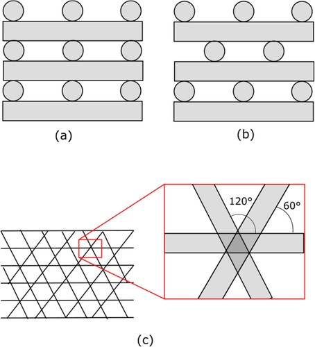
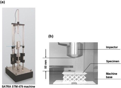
Figure 15. (a) Equipment and (b) experimental setup for the falling mass shock absorption tests used in (Jhou, Hsu, and Yeh Citation2021).
Effect of overlap between rasters in adjacent layers. The amount of material shared between adjacent layers becomes relevant in woodpile structures. This has an impact on the type of joining mechanisms between two rasters that are separated in the stacking direction. These mechanisms can be between a fully welded joint or a pin joint. Which type of joining appears in each 3D printed structure cannot be easily determined. Computational and laboratory experiments have demonstrated the relationship between stiffness and the different joining mechanisms (Cuan-Urquizo and Bhaskar Citation2018). Authors in (Cuan-Urquizo and Bhaskar Citation2018), ran several FE simulations on woodpile beams with different percentages of overlap between layers and reported the shear stiffness; as the overlap increases, the response converges to the case of a fully welded joint. Naghieh et al. (Citation2016) reported that for an increase of 0.4 mm in interlayer penetration, the compressive modulus was 4 times higher.
4.2.5 Mechanical characterization of lattice structures under bending
Two scenarios have been considered when studying the flexural response of MM. In the first, researchers have tested lattice beams as single elements. In the second, MM have been evaluated as part of sandwich structures, i.e. MM cores joined to sheets/skins.
Studies focusing on the flexural behavior of lattice beams include diverse 2D and 3D unit cell types (Bru et al. Citation2020; Dong et al. Citation2018; Valle et al. Citation2022; Beloshenko et al. Citation2021; Antony, Cherouat, and Montay Citation2020; Araújo et al. Citation2019; Cuan-Urquizo et al. Citation2022; Lu et al. Citation2018) and different thermoplastic materials. In contrast, sandwich constructions have included a wide variety of cores and sheets. In some cases, both lattice core and sheets were built integrally using FFF (Monteiro et al. Citation2021; Brischetto et al. Citation2018; Brischetto and Torre Citation2020; Essassi et al. Citation2020; Yazdani Sarvestani et al. Citation2018) (a); in other cases, AM-fabricated lattice cores were joined to sheets using adhesives (b). This includes lattice cores and sheets built separately via FFF and then joined with adhesive (Antony, Cherouat, and Montay Citation2020), and composite sheets built by other methods (Lu et al. Citation2018; Hou et al. Citation2013). Among the feedstock materials used for the fabrication of specimens, we found PLA (Monteiro et al. Citation2021; Araújo et al. Citation2019; Lu et al. Citation2018; Yazdani Sarvestani et al. Citation2018), ABS (Gullapalli et al. Citation2020), ABS plus (Valle et al. Citation2022; Hou et al. Citation2013); TPU (Beloshenko et al. Citation2021), PC (Gajdoš et al. Citation2015), in addition to PLA reinforced with vegetal fibers such as hemp (Antony, Cherouat, and Montay Citation2020), wood (Cuan-Urquizo et al. Citation2022), and flax (Essassi et al. Citation2020).
Figure 14. (a) 3D printed sandwich beams. Both core and skins are integrally built by FFF, with permission from Elsevier (Yazdani Sarvestani et al. Citation2018); (b) Sandwich panels with honeycomb cores produced by FFF. The sandwich panels were made by bonding two layers of composite skins using epoxy super glue, with permission from Elsevier (Hou et al. Citation2013).
The effect of multiple parameters on the flexural behavior of lattice-based beams has been investigated, including unit-cell type, core density (Essassi et al. Citation2020), cell orientation (flatwise/edgewise) (Beloshenko et al. Citation2021; Antony, Cherouat, and Montay Citation2020), build/print orientation (Beloshenko et al. Citation2021; Essassi et al. Citation2020), skin/shell material (PLA/ABS) (Brischetto et al. Citation2018), filleting in cell walls (Araújo et al. Citation2019), unit-cell type in core (Bru et al. Citation2020; Monteiro et al. Citation2021; Beloshenko et al. Citation2021; Araújo et al. Citation2019; Cuan-Urquizo et al. Citation2022; Lu et al. Citation2018; Gullapalli et al. Citation2020), infill density (Cuan-Urquizo et al. Citation2022), and the re-entrant angle in 2D (Hou et al. Citation2013) and 3D (Valle et al. Citation2022) auxetic structures.
The most common unit cell type for beams or core structures has been the hexagonal honeycomb (Bru et al. Citation2020; Monteiro et al. Citation2021; Beloshenko et al. Citation2021; Antony, Cherouat, and Montay Citation2020; Araújo et al. Citation2019; Brischetto et al. Citation2018; Brischetto and Torre Citation2020; Gullapalli et al. Citation2020; Gajdoš et al. Citation2015) and its variants of (Bru et al. Citation2020; Araújo et al. Citation2019), but other geometries such as circular (or lotus) (Araújo et al. Citation2019; Gullapalli et al. Citation2020), tri and star arrangements (Cuan-Urquizo et al. Citation2022), tri-grid, bi-grid, quadri-grid and kagome-grid (Lu et al. Citation2018), and diamond (Gullapalli et al. Citation2020) has been investigated. The flexural response of auxetic unit cells has also raised interest (Essassi et al. Citation2020; Hou et al. Citation2013). The flexural strength of 3D lattice beams was also investigated, including BCC cell variants and parallelepiped (Monteiro et al. Citation2021), functionally graded lattices (Wen and Li Citation2021), auxetic cells (Valle et al. Citation2022) and other surface-based unit-cells such as gyroid (Beloshenko et al. Citation2021) and cubic, octet and cubic/octet cellular cores (Yazdani Sarvestani et al. Citation2018).
Both 3-point (Bru et al. Citation2020; Valle et al. Citation2022; Beloshenko et al. Citation2021; Araújo et al. Citation2019; Cuan-Urquizo et al. Citation2022; Lu et al. Citation2018; Brischetto and Torre Citation2020; Yazdani Sarvestani et al. Citation2018; Hou et al. Citation2013; Gullapalli et al. Citation2020) and 4-point bending tests (Antony, Cherouat, and Montay Citation2020) were used to study flexural behavior using different standards including ASTM D790, ASTM D6273, and ISO 178 for plastic core materials; the sandwich constructions were tested under standards ASTM C393 or GB T1456. Other studies did not report the use of a specific standard or used customized specimens.
The role of the core density and unit cell type in the flexural properties is quite clear, with higher relative densities, and 2D honeycomb structures showing a higher stiffness compared to 3D lattices. The delamination between layers represents a significant constraint to achieve high performing structures using FFF. Nevertheless, research remains at its early stages, as the emergence of new materials (flexible, composites) and topologies (auxetic, FGCS, etc.) open new directions to be explored.
4.2.6 Characterization of FFF structures under dynamic loading conditions
Studies on the dynamic response of honeycombs (Bates, Farrow, and Trask Citation2019; Khare et al. Citation2018; Ben Ali et al. Citation2019; Yazdani Sarvestani et al. Citation2018; Kucewicz et al. Citation2019), 3D cell-based lattice structures (Azmi et al. Citation2018; Jhou, Hsu, and Yeh Citation2021; Sun, Guo, and Shim Citation2022; Ge et al. Citation2018; Lvov et al. Citation2020; Duan et al. Citation2019; Essassi et al. Citation2020; Yazdani Sarvestani et al. Citation2018) and scaffolds/woodpiles (Baptista and Guedes Citation2019; Miller et al. Citation2017; Gong et al. Citation2017; Senatov et al. Citation2016) are very broad in scope, including experiments focused on evaluating their behavior under cyclic loading (Bates, Farrow, and Trask Citation2019; Ge et al. Citation2018; Lvov et al. Citation2020), low-cycle (Khare et al. Citation2018; Lvov et al. Citation2020; Baptista and Guedes Citation2019; Essassi et al. Citation2020; Gong et al. Citation2017; Senatov et al. Citation2016) and high-cycle (Miller et al. Citation2017) fatigue behavior, the effect of loading rate (Duan et al. Citation2019), and impact at both low velocity (drop test, 10−2 s−1, ) (Jhou, Hsu, and Yeh Citation2021; Sun, Guo, and Shim Citation2022; Yazdani Sarvestani et al. Citation2018) and high speed (direct impact Hopkinson pressure bar test, 102–104 s−1 (Duan et al. Citation2019)). Additionally, some studies have explored the vibration absorption capacity (Azmi et al. Citation2018) and cushion material properties (Ge et al. Citation2018) of these materials.
Senatov et al. (Senatov et al. Citation2016) studied the failure mechanisms of PLA scaffolds (woodpile structures) under dynamic loading, finding similarities to those reported for quasi-static loading: delamination, cell collapse, bending or shearing of walls/struts and propagation of cracks across layers (Section 5.3 includes a more detailed discussion on this type of failure). The topology is susceptible to shear stress, but this could be reduced by adjusting the gap between rasters; the larger the gap, the more sensitive to shear the structure becomes. On the other hand, other studies have reported that deformation patterns in the mesoscopic structures were affected by an increase in strain rate, with a more localized deformation near the loading plates under dynamic conditions (Duan et al. Citation2019), which suggests that further study might be required.
Two recent trends in the dynamic analysis of metamaterials have been the use of flexible materials (for instance TPU) (Bates, Farrow, and Trask Citation2019; Jhou, Hsu, and Yeh Citation2021; Ge et al. Citation2018; Lvov et al. Citation2020; Kumar et al. Citation2020; Miller et al. Citation2017) and/or auxetic unit cells (Khare et al. Citation2018; Lvov et al. Citation2020; Essassi et al. Citation2020; Yazdani Sarvestani et al. Citation2018), to take advantage of their elastic recovery properties. Some researchers (Jhou, Hsu, and Yeh Citation2021; Kumar, Verma, and Jeng Citation2020) studied the effect of density (wall thickness) and unit-cell type on the energy absorption capacity of TPU lattices, reporting that a stiffer cell shape and a higher density led to improved performance. These structures outperformed ethylene vinyl acetate (EVA) foams in terms of stiffness and energy absorption (Kumar, Verma, and Jeng Citation2020) and offer the potential to create high-performance cushion materials tailored for packaging applications (Ge et al. Citation2018). Similarly, auxetic lattice structures, in which geometric parameters can be modified to tune the material’s elastic strain and Poisson’s ratio (Khare et al. Citation2018), can be potentially used for mechanical energy dissipation (Lvov et al. Citation2020). For instance, in (Khare et al. Citation2018), auxetic (3D re-entrant) and non-auxetic (3D hexagonal) topologies were compared. Although both structures were bending-dominated, the auxetic topology collapsed, while the non-auxetic showed more stability coupled with transverse expansion. The collapse of the auxetic structure could be attributed to the negative Poisson’s ratio, as it shrinks transversally which in turn reduced the overall area of the samples, leading to buckling.
5. Analysis of the deformation and failure mechanisms in mechanical metamaterials
The deformation process and failure mechanisms in lattice structures have been analyzed using different methods and scales, that range from the microscopic evolution of damage and the deformation of unit cells to the macroscopic failure of the metamaterials. Typically, mesoscopic is applied in this context to the geometric features in the range of 0.1–10 mm, while the microscale is defined as anything below 0.1 mm (Tang et al. Citation2018; Guerra Silva et al. Citation2020). Hence, the response of the interconnected struts and nodes inside the truss-like structure is mesoscopic, but the failure mechanisms inside a single strut are microscopic.
5.1 Failure analysis at the microlevel
Optical, digital and scanning electron microscopes (SEM) have been typically used for the analysis of fracture surfaces, to identify microscopic failure or damage mechanisms, i.e. delamination and stress whitening. For instance, (de Aquino, Maskery, and Longhitano Citation2020) reported evidence of crack initiation in SEM images due to debonding between layers in woodpile and gyroid scaffolds, with different fracture behaviors in different load directions, although the same response was not observed in diamond scaffolds. Gautam et al. (Citation2018) observed differences in the failure modes according to load orientation in the fracture surface using SEM, with evidence of a fast fracture and crack propagation under shear stress and debonding between adjacent layers. A similar result was reported in (Kladovasilakis et al. Citation2021), where authors observed the detachment of layers and diagonal shearing across samples using optical microscopy (). Maconachie et al. (Citation2020) also used optical microscopy for the observation of the gyroid lattice specimens, reporting that although cracks typically initiate between layers, they can propagate across layers, which suggests that failure is dominated by lattice geometry and not the FDM process. Stress whitening was also observed near damaged regions. Similarly, in (El Jai et al. Citation2021), the authors reported the whitening of the thinner sections in lattices during compression tests, with the failure of the amorphous polymers caused by the cavitation phenomena, followed by crazing. (Khan et al. Citation2019) and (Kucewicz et al. Citation2019) also reported the presence of stress whitening in optical micrographs near the failure region of struts.
Figure 16. Top: Fracture areas at 15% strain for different TPMS structures, showing delamination and crack propagation across layers (Kladovasilakis et al. Citation2021). Bottom: Debonding between contour rasters at the cell wall level reported in (Lam et al. Citation2019).
As mentioned in Section 3.1, for 2D structures fabricated lying on the printing plane, the cell walls are formed from multiple rasters. The failure of such structures could be influenced by the debonding of these rasters. This was observed by Zaharia et al. (Citation2020). Lam et al. (Citation2019) reported debonding between contour rasters induced by plastic hinges caused by the bending of cell walls. This phenomenon is observed in the bottom section of . Note that in the bottom left corner the cell wall has bent, resulting in failure by debonding.
Microscopic analysis has also been used to identify FFF defects at the raster level (airgaps, stringing, staircase-stepping, layer separation) (Ben Ali et al. Citation2019; Bian et al. Citation2021; Khan et al. Citation2019; Araújo et al. Citation2019; Cuan-Urquizo et al. Citation2022) or form deviations (Alizadeh-Osgouei et al. Citation2021), that might impact the mechanical response of lattices (Ben Ali et al. Citation2019) (). For instance, Tang et al. (Citation2020) studied the fracture surface of PLA lattices using SEM, reporting an interrelation between the mechanical properties and the microscopic defects caused by variations in the printing temperature and speed. Wen et al. (Citation2021) also evaluated the fracture surface of specimens with different unit-cell types under SEM, reporting imperfections (stringing, holes and rough edges) that might act as stress concentrators that lead to strut failure and the crushing of layers.
Figure 17. Micrographic images with 50× magnification showing defects on the bottom side of PLA-wood lattice samples (Cuan-Urquizo et al. Citation2022).
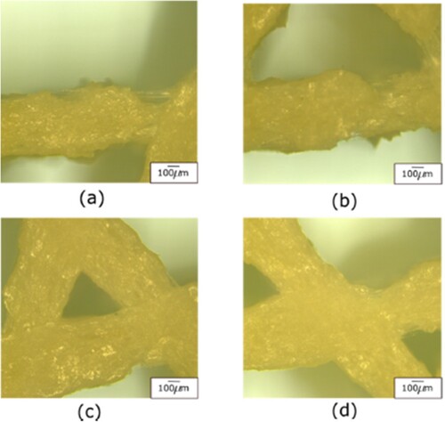
Microscopy has also been used to assess the damage evolution in lattices under dynamic loading conditions. Lvov et al. (Citation2020) analyzed samples of TPU auxetic lattices after 500 cycles of alternative loading using SEM images, reporting that no signs of deterioration at the nodes in both geometric structures were visible. Similarly, (Baptista and Guedes Citation2019) reported similar results after analyzing PLA scaffolds using optical microscopy and scanning electron microscopy (SEM) after 3600 cycles. On the other hand, Senatov et al. (Citation2016) studied PLA-based 3D porous scaffolds after cyclic loading by fractographical studies with SEM reporting visible shear deformation, growth of cracks, delamination and fracture of layers after 4000 cycles, as shown in . Micro-computed tomography (CT) scanning has also been used to detect defects and geometric deviations in the internal printed structures (Germain et al. Citation2018) as the ones presented in .
Figure 18. Fractographical studies with SEM showing the structure of PLA/HA porous scaffold, with permission from Elsevier (Senatov et al. Citation2016).
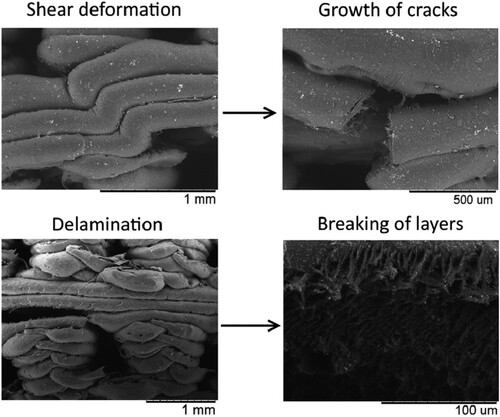
Figure 19. Model (a) and printed gyroid μCT scan (b) both cropped at the front and the top of the structure for the sake of visualization. Model (c) and μCT scan (d) of the corresponding printed cross-sections, with permission from Elsevier (Germain et al. Citation2018).
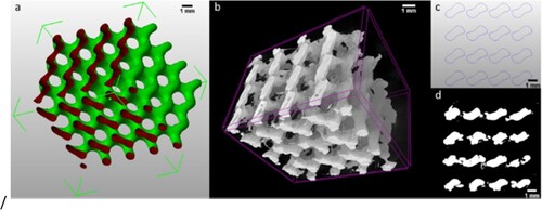
5.2 Failure analysis at the mesoscopic level
Analyses of lattices at the mesoscopic level allow the exploration of the deformation of struts and single cells (stretch-dominated vs. bending-dominated), the emergence of deformation patterns in samples, and the evolution of damage (collapse or crushing of clusters of cells, shear bands, normal vs shear deformation).
The deformation of lattice structures at the mesoscopic level has been commonly studied using sequential photographs of the specimens at different strain levels. The images have been obtained using standard or high-resolution photo cameras, through time-lapse video or individual images extracted from videos of the compression test. In the case of dynamic tests, high-speed cameras have been required to analyze the state of deformation frame by frame (Kucewicz et al. Citation2019). The deformation distribution has also been studied using the digital imaging correlation (DIC) method and CT scan imaging, a non-destructive technique that could be used to analyze strain distribution in lattice structures (Sun, Guo, and Shim Citation2021; Tang et al. Citation2018; Hou et al. Citation2013).
In general, the deformation in lattices can be either uniform or localized (Sun, Guo, and Shim Citation2021; Guerra Silva et al. Citation2021). When localization occurred, a handful of patterns were observed. In some cases, lattices collapsed layer-by-layer, normally beginning from the top or the bottom end, while in other cases, shear bands beginning from the edges were present, sometimes forming X or V patterns (Sun, Guo, and Shim Citation2021; Sun, Guo, and Shim Citation2021; Duan et al. Citation2019; Kumar et al. Citation2020; Gong et al. Citation2017; Rezaei et al. Citation2021) as shown in . Note that here the word ‘layer’ is used for rows of cells, and it does not represent the layers of deposited material encountered in FFF. In contrast, Maharjan et al. (Citation2018) reported uniformly distributed deformation across all unit cell layers in gyroid lattice under compression.
Figure 20. Photographic images showing different deformation mechanisms in lattices with different unit-cell types at various strains, with permission from Elsevier (Sun, Guo, and Shim Citation2021).
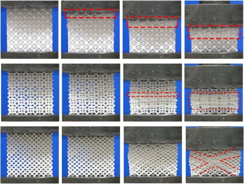
Kladovasilakis et al. (Citation2021) studied different TPMS topologies and reported different deformation modes, highlighting the influence of the unit-cell type on the deformation pattern. Similarly, Guerra Silva et al. (Citation2021) compared the deformation patterns in different strut-based lattice structures, observing that some structures showed uniform deformation, while others presented either a diagonal shear band or a layer-by-layer collapse, and concluded that the deformation pattern was strongly dependent on unit-cell type and the constituent solid material. Maconachie and co-workers (Citation2020) also reported a similar outcome for gyroid lattices under compression, with different deformation modes depending on cell size. Khan et al. (Citation2019) also suggested a possible connection between cell size and the resulting deformation patterns. Abusabir et al. (Citation2022) studied the deformation mechanism in strut and wall-based cubic lattice structures under compression, all showing the same layer-wise collapse in the mid-section of the specimens.
Sequential photographs can also be used to study the deformation process of individual elements (struts, walls, unit-cells) inside the lattice structure. For instance, authors in (Tang et al. Citation2020) identified local brittle cracks caused by an excessive printing temperature using this technique. Wen and Li (Citation2021) also used sequential photographs to evaluate the failure of different unit-cell lattices with vertical struts under compression and identified elastic flexure as the principal deformation mechanism of the struts, with most fractures occurring near joints.
Photographs have been used also to study the failure behavior of sandwich structures with lattice cores under bending, identifying face sheet debonding and core shear when the core and sheets were of dissimilar materials (Lu et al. Citation2018; Hou et al. Citation2013). In integrally built sandwich panels, the failure of the 3D lattice began at the struts, while the sheet remained intact. On the other hand, in honeycomb sandwich panels the failure started at the skin and then propagated to the core (Monteiro et al. Citation2021). A similar result was observed by authors in (Yazdani Sarvestani et al. Citation2018) in integrally built sandwich beams with closed-cell lattice cores under quasi-static bending, with different failure mechanisms depending on unit-cell type and relative density of the core: core buckling, face-sheet failure, core buckling and shear.
Although numerical models can predict deformation patterns in lattice structures (Fadeel et al. Citation2019; Sun, Guo, and Shim Citation2021; Sun, Guo, and Shim Citation2021; Ge et al. Citation2018; Kucewicz et al. Citation2019; Habib et al. Citation2017; Kucewicz et al. Citation2018; Wu et al. Citation2019), not all models reported in the literature offered the same capabilities (Dong et al. Citation2018; Bian et al. Citation2021). Because no clear rule is available to predict which deformation pattern will emerge from a given unit-cell type and cell size combination, the role of numerical simulation in the design stage becomes extremely important.
5.3 Failure analysis at the macroscopic level
At the macroscopic level, the characterization of the effective mechanical properties (elastic modulus, plateau stress, Poisson’s ratio, energy absorption capacity) has been the main objective. The effective mechanical properties of metamaterials were presented in Section 4.2. In mechanical testing, the material is considered as a continuum, leaving aside the specific distribution of solid material and voids. This is the same principle used for the development of equivalent homogeneous materials (EHM) and empirical models based on the power law proposed by (Ashby et al. Citation2000). Typically, the focus is on the relative density of the structure and the relationship between the mechanical properties of the metamaterial and those of the solid constituent.
Using this approach, some basic facts can be observed. For instance, the compressive strength of lattice structures is directly correlated to their density. In general, a higher density leads to a higher compressive strength (Guerra Silva et al. Citation2021; Maharjan et al. Citation2018). It is also possible to identify which unit-cell type offers the best mechanical properties for a given density (Guerra Silva et al. Citation2021). Because the solid volume fraction is determined by strut thickness, cell size and unit-cell type, there is a strong correlation between these parameters.
Furthermore, because the failure mechanisms and mechanical response in lattices are the consequence of interactions between the different levels, an analysis considering different levels and how they interrelate is advantageous. Al Rifaie et al. (Citation2019) analyzed the failure progression of BCC lattices using time-lapse videos, correlating abrupt decreases in the stress–strain curves with the collapse of specific layers of the structure. Works in (Intrigila, Nodargi, and Bisegna Citation2022; Ben Ali et al. Citation2019) have also correlated the emergence of deformation patterns to the stress–strain curves, highlighting the mechanisms of progressive collapse in lattices. Works by Sun et al. (Citation2021a, Citation2021b) also studied deformation patterns in different lattice structures and their relationship to the stress–strain behavior of lattices, highlighting the importance of unit-cell type in the resulting deformation pattern. In some lattices (octet and diamond) the number of peaks in the stress–strain curve can be associated with the number of layers in the lattice sample, relating the collapse of single layers and stress variations (Maconachie et al. Citation2020; Kladovasilakis et al. Citation2021; Kucewicz et al. Citation2019).
Another approach for the multiscale analysis of lattice structures as homogeneous material is based on digital image correlation (DIC). The method uses the displacement of reference points at the outer shell of specimens to estimate the continuous strain distribution in the specimen (Duan et al. Citation2019; Podroužek et al. Citation2019), see for example .
Figure 21. Deformation distribution in cellular materials (Kelvin cell) for different relative densities under quasi-static loading at a nominal strain of 20% obtained through DIC analysis, showing shear bands with 45° and X-shaped deformation patterns, with permission from Elsevier (Duan et al. Citation2019).
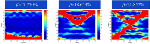
Another issue of interest in the characterization of metamaterials is the potential deviation in stress–strain curves between samples of the same metamaterial that could be attributed to manufacturing errors. Due to the lack of a specific standard for the characterization of these materials, each author has used a different number of samples, ranging from one to five. Although the works in (Al Rifaie, Mian, and Srinivasan Citation2019; Guerra Silva et al. Citation2021) reported variations in the stress–strain curves among samples of the same lattice structures, Guerra Silva et al. (Citation2021) reported little variation in the stress–strain curves between samples. Another topic that has been scarcely explored is the role of boundary and size effects on the overall response of metamaterials (Guerra Silva, Torres, and Zahr Viñuela Citation2021). The dimensions of samples also varied from one study to the next, and it is difficult to determine whether the observed mechanical behavior was affected by the effect of the sample-to-cell ratio.
5.4 Computational modelling of mechanical metamaterials
Aware of the advantages of the computational resources available and the limitations of the experimental techniques, several works exploring the deformation mechanisms in FFF porous structures have included computational analysis.
Taking advantage of the periodicity of many lattice metamaterials, some works have characterized the mechanical properties by simulating a single-unit cell (Gautam, Idapalapati, and Feih Citation2018; Cuan-Urquizo, Shalchy, and Bhaskar Citation2020). This approach demands a proper implementation of the boundary conditions, or it could lead to inaccurate results (Cuan-Urquizo, Shalchy, and Bhaskar Citation2020). Other models have employed symmetry boundary conditions (Jhou, Hsu, and Yeh Citation2021), using only ¼ of the sample to successfully predict the deformation values. The use of rigid elements has also been explored as these ensure a uniform distribution of the load (a). The absence of these could lead to stress and local strain concentrations at the edges or loading application regions, diminishing the cellular topology participation in the mechanical response.
Figure 22. Relevant considerations for FE computations: (a) Model of the compression test of hexagonal honeycombs showing the rigid plates used to model the boundary conditions (Płatek et al. Citation2020), (b) Comparison of load-displacement curves for ABS hexagonal honeycomb from experiments and FE simulations using different finite element types (bricks, shell and beams) done by Kucewicz et al., with permission from Elsevier (Kucewicz et al. Citation2018), and (c) Beam model of a strut with non-uniform cross-section (top) based on the form deviation observed in lattices built by FFF(bottom), with permission from Elsevier (Ravari MR et al. Citation2014).
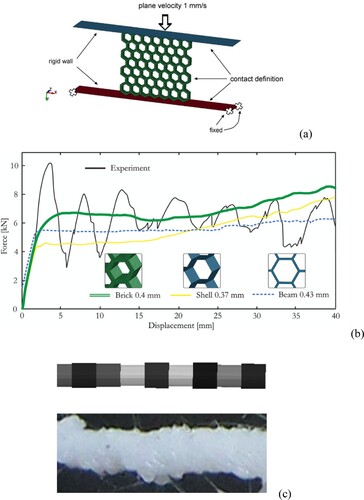
Most of the FEA approximations to study the mechanical properties of MM have used 3D finite elements, e.g. with tetrahedral (Sun, Guo, and Shim Citation2021; Citation2021) and hexahedral (Abdulhadi and Mian Citation2019) elements. However, 1D beam element models could be used (Al Nashar and Sutradhar Citation2021; Cuan-Urquizo, Yang, and Bhaskar Citation2015; Ajdari et al. Citation2012). The cell walls in honeycombs can also be modeled using shell elements which resulted in good predictions for both linear elastic response and progressive buckling (plateau) (Ingrole, Hao, and Liang Citation2017; Habib et al. Citation2017), enabling the computational characterization of the energy absorbed and the deformation-mechanism of both open- (Rebelo et al. Citation2019) and closed-wall topologies (Duan et al. Citation2019).
While these types of elements can replicate the physics of lattices up to a certain level, they fail to incorporate aspects encountered in structures built by AM. For instance, a comparison of different types of finite elements in the modeling of hexagonal honeycombs was presented in (Kucewicz et al. Citation2018) (b). In (Kucewicz et al. Citation2018), 3D (brick), 2D (shell) and 1D (beam) elements were used to model the cell walls of the hexagonal honeycomb. The three element types achieved a fair prediction in the elastic region but failed to reflect the mechanical response in the plateau region.
Features intrinsic to FFF such as the staircase effect and geometric deviations have not been typically included in the computational models. Few works have incorporated such features in their models to study how these affect the mechanical and structural properties. Karamooz Ravari et al. (Citation2014) incorporated the variation of strut diameter in FFF 3D lattice structures (see c). As the discretization became finer, the accuracy of the compressive properties predicted by the model improved: estimating errors were reduced from 127.9% to 6.1% for solid 3D finite element models, and to 22.7% when using 1D beam elements. An alternative FEA approach was proposed by Park et al. (Citation2014), who presented a homogenization method that accounted for possible variations in strut shape cross-section.
6. A comparison of FFF with other additive manufacturing processes
Although the choice of AM technology is normally defined by functional requirements, in some cases different processes are capable of producing fully functional geometries with similar mechanical properties. While the differences in available materials and software make a direct comparison challenging, some authors have made attempts at identifying the benefits and constraints of different AM technologies for the production of MM.
For instance, Habib et al. (Citation2017) compared the multi-jet fusion (MJF) and FFF processes for the production of octagonal lattices, reporting better mechanical properties in MJF samples. Sun et al. (Citation2022) compared the dynamic responses in different lattices fabricated by SLS and FFF, reporting that SLS-fabricated specimens were much more brittle. This behavior was attributed to the voids and the presence of unmelted powder in sintered specimens, but they failed to address the potential effect of using different feedstock materials, PA12 in SLS and PLA in FDM (Sun, Guo, and Shim Citation2022). In both studies, the focus was on mechanical properties, and dimensional accuracy or geometric deviations in specimens were not addressed.
Guerra Silva et al. (Citation2021) compared different lattice structures fabricated using FFF and Digital Light Processing (DLP) under compression. On one hand, DLP allowed a higher geometrical accuracy: the average strut diameter in FFF lattices was around 0.96 mm, while in DLP lattices it was approximately 0.74 mm, with the latter closer to the nominal value of 0.70 mm. On the other hand, the mechanical response was strongly dependent on cell type, with little difference between DLP and FDM samples in some cases, and a larger one in some others. A similar effect was reported by Sun et al. (Citation2022) between different cell types, which suggests that comparisons between AM methods when dealing with MM is not universally valid for all unit cell types.
Compared the compression behavior of BCC lattices built using FFF and MJF. Similar to the work by Sun et al. (Citation2022), both lattices were fabricated using two different constituent materials, PLA and PA12 respectively. Although both constituent materials have different mechanical properties and were fabricated using different methods, the lattices showed almost identical deformation modes and similar stress–strain responses. A third sample, built in AlSI10Mg using selective laser melting (SLM) was contrasted to the polymer specimens. The similarities in the deformation mode and stress–strain curve characteristics reported for the three materials (PLA, AlSi10Mg and PA12) suggests that for some particular unit cell geometries less expensive materials and AM processes could be used for prototyping, with the caveat that this might not be valid for all lattice structures.
In comparison to other AM processes, only MJF has proved capable of offering better mechanical properties than FFF on a level playing field. On the other hand, SLS and DLP provide a comparable mechanical behavior compared to FFF, but the use of different feedstock materials in these processes makes a direct comparison difficult. Further study is necessary to understand the interactions between constituent material, cell geometry and AM process given the influence of unit-cell type on the macroscopic response of MM.
7. Concluding remarks and future work
The field of cellular, lattice materials and mechanical metamaterials has benefited from the advent of AM techniques, being FFF one of the most popular. From the literature reviewed presented here, the following conclusions can be drawn:
Mechanical metamaterials encompass a variety of structures that include cellular and porous materials, scaffolds and lattices; in addition to these categories, infill patterns used in FFF, which are typically a lattice or scaffold-like structure, should be considered also MM.
When compared to other AM processes, FFF is equally capable of producing functional, self-supporting structures in different sizes and in a wide variety of materials. FFF also opens new opportunities for the production of multimaterial MM or flexible parts that are not currently possible with other AM processes.
A variety of 2D and 3D cellular topologies in a wide range of sizes can be fabricated using FFF without the need for support material. Moreover, new unit-cell geometries are constantly proposed and tested in the literature.
2D Honeycombs are easily fabricated due to their building simplicity. On the other hand, strut base 3D lattices are often fabricated with numerous geometric deviations, as struts are fabricated at orientations out of the printing plane. Common geometric deviations are uneven cross-sections along the strut’s length and staircase effect. Although structures can be designed to be self-supporting, the use of support is often an important consideration.
Similarly, TPMS and other 3D surface-based geometries could be fabricated without the use of supports, but the staircase effect could become decisive in their structural failure, due to crack initiation arising from debonding of layers.
Among the design and topology parameters, relative density and all related parameters (cell type and size, strut/wall thickness) have the largest influence on the mechanical properties of MM, while other geometrical parameters play only a secondary role.
Among AM parameters, the manufacturing process, printing/load orientation and postprocessing have the larger influence on mechanical properties. Other parameters such as printing temperature and speed, and layer thickness have a minor effect on them.
Different failure analysis techniques could be applied to analyze MM depending on the focal point. While macroscopic analysis might be useful in the design stages and validation of numerical models, microscopic and mesoscopic analysis are more relevant when evaluating damage evolution or the relationship between the mechanical response and the process parameters. For instance, the failure mechanisms at the strut or cell wall level, are connected to the delamination and the raster and layer distribution in FFF.
Geometric deviations and non-linearities of the constituent material related to the AM process should be considered when applying finite element analysis to MM built by FFF.
7.1 Future work
Further research along the following lines is still necessary:
There is a need for standardization of the mechanical testing of AM cellular and lattice metamaterials, similar to that already available for cellular metallic materials. Previous works often follow ad-hoc experimental setups which hinder the direct comparison of results. For instance, the effect of the sample-to-cell ratio must be revisited to consider the typically larger cell size produced in FFF porous and cellular materials.
A clear relationship between the manufacturing parameters and failure mechanisms is still needed and requires further research with a more systematic approach. Each unit cell type offers unique cell wall composition, strut formation, etc., that interact differently with layer deposition in different ways and define the failure or fracture mechanisms.
Better and more accurate numerical models are necessary to better assess the potential of different and novel cellular structures before manufacturing.
Dynamic properties must be further studied, especially considering the potential of these groups of materials for energy absorption applications and the limited information currently available. The development of new auxetic structures and new available highly elastic materials such as TPU are opening new opportunities for applications involving dynamic and/or cyclic loading.
Future studies focusing on the mechanical properties of infill patterns, orientation or density should explore concepts like rotational symmetry or deformation mechanisms that give insight into their behavior.
New developments involving the use of curved layered (CL) FFF to build conformal structures should be further explored, which could have a potential impact in the design of MM (Rodriguez-Padilla et al. Citation2021). CLFFF enables the fabrication of non-conventional macro shapes (e.g. domes, biomedical sockets-reinforcements, fuselages, etc.) built out of conformal cellular and lattice topologies (Barreto et al. Citation2022).
The development of new AM systems based on robot arms with extruders that enable FFF multi-plane system deposition are a very promising tool for the production of multidirectional self-supporting 3D lattice structures. Similarly, 5-axis FFF concepts that have been proposed could be of interest in the field.
Disclosure statement
No potential conflict of interest was reported by the author(s).
References
- Abdulhadi, H. S., and A. Mian. 2019. “Effect of Strut Length and Orientation on Elastic Mechanical Response of Modified Body-Centered Cubic Lattice Structures.” Proceedings of the Institution of Mechanical Engineers, Part L: Journal of Materials: Design and Applications 233: 2219–2233. doi:10.1177/1464420719841084.
- Abusabir, A., M. A. Khan, M. Asif, and K. A. Khan. 2022. “Effect of Architected Structural Members on the Viscoelastic Response of 3D Printed Simple Cubic Lattice Structures.” Polymers (Basel) 14 (3): 618. doi:10.3390/polym14030618.
- Ajdari, A., B. H. Jahromi, J. Papadopoulos, H. Nayeb-Hashemi, and A. Vaziri. 2012. “Hierarchical Honeycombs with Tailorable Properties.” International Journal of Solids and Structures 49: 1413–1419. doi:10.1016/j.ijsolstr.2012.02.029.
- Akhoundi, B., and A. H. Behravesh. 2019. “Effect of Filling Pattern on the Tensile and Flexural Mechanical Properties of FDM 3D Printed Products.” Experimental Mechanics 59: 883–897. doi:10.1007/s11340-018-00467-y.
- Al Nashar, M., and A. Sutradhar. 2021. “Design of Hierarchical Architected Lattices for Enhanced Energy Absorption.” Materials (Basel) 14: 5384. doi:10.3390/ma14185384.
- Al Rifaie, M., A. Mian, and R. Srinivasan. 2019. “Compression Behavior of Three-Dimensional Printed Polymer Lattice Structures.” Proceedings of the Institution of Mechanical Engineers, Part L: Journal of Materials: Design and Applications 233: 1574–1584. doi:10.1177/1464420718770475.
- Alizadeh-Osgouei, M., Y. Li, A. Vahid, A. Ataee, and C. Wen. 2021. “High Strength Porous PLA Gyroid Scaffolds Manufactured via Fused Deposition Modeling for Tissue-Engineering Applications.” Smart Materials in Medicine 2: 15–25. doi:10.1016/j.smaim.2020.10.003.
- Ambekar, R. S., E. F. Oliveira, B. Kushwaha, V. Pal, L. D. Machado, S. M. Sajadi, R. H. Baughman, P. M. Ajayan, A. K. Roy, D. S. Galvao, et al. 2021. “On the Mechanical Properties of Atomic and 3D Printed Zeolite-Templated Carbon Nanotube Networks.” Additive Manufacturing 37: 101628. doi:10.1016/j.addma.2020.101628.
- An, D.-S., T. H. Kim, and E.-H. Lee. 2021. “Analytical and Experimental Investigation Into the Relative Influence of Core and Side Parts on Structures Laminated by Fused Deposition Modeling.” International Journal of Precision Engineering and Manufacturing-Green Technology 8: 13–27. doi:10.1007/s40684-019-00177-3.
- Antony, S., A. Cherouat, and G. Montay. 2020. “Fabrication and Characterization of Hemp Fibre Based 3D Printed Honeycomb Sandwich Structure by FDM Process.” Applied Composite Materials 27: 935–953. doi:10.1007/s10443-020-09837-z.
- Araújo, H., M. Leite, A. R. Ribeiro, A. M. Deus, L. Reis, and M. F. Vaz. 2019. “The Effect of Geometry on the Flexural Properties of Cellular Core Structures.” Proceedings of the Institution of Mechanical Engineers, Part L: Journal of Materials: Design and Applications 233: 338–347. doi:10.1177/1464420718805511.
- Ashby, M. F. 1983. “The Mechanical Properties of Cellular Solids.” Metallurgical Transactions A 14: 1755–1769. doi:10.1007/BF02645546.
- Ashby, M. F., A. G. Evans, N. A. Fleck, L. J. Gibson, J. W. Hutchinson, and H. N. G. Wadley. 2000. Metal Foams, A Design Guide. Chapter 4 – Properties of metal foams. Butterworth-Heinemann. doi: 10.1016/B978-075067219-1/50006-4.
- Askari, M., D. A. Hutchins, P. J. Thomas, L. Astolfi, R. L. Watson, M. Abdi, M. Ricci, S. Laureti, L. Nie, S. Freear, et al. 2020. “Additive Manufacturing of Metamaterials: A Review.” Additive Manufacturing 36: 101562. doi:10.1016/j.addma.2020.101562.
- Attard, D., P. S. Farrugia, R. Gatt, and J. N. Grima. 2020. “Starchirals–A Novel Class of Auxetic Hierarchal Structures.” International Journal of Mechanical Sciences 179: 105631. doi:10.1016/j.ijmecsci.2020.105631.
- Auricchio, F., A. Bacigalupo, L. Gambarotta, M. Lepidi, S. Morganti, and F. Vadalà. 2019. “A Novel Layered Topology of Auxetic Materials Based on the Tetrachiral Honeycomb Microstructure.” Materials and Design 179: 107883. doi:10.1016/j.matdes.2019.107883.
- Azmi, M. S., R. Hasan, R. Ismail, N. A. Rosli, and M. R. Alkahari. 2018. “Static and Dynamic Analysis of FDM Printed Lattice Structures for Sustainable Lightweight Material Application.” Progress in Industrial Ecology 12: 247–259. doi:10.1504/PIE.2018.097063.
- Baptista, R., and M. Guedes. 2019. “Fatigue Behavior of Different Geometry Scaffolds for Bone Replacement.” Procedia Structural Integrity 17: 539–546. doi:10.1016/j.prostr.2019.08.072.
- Barreto, M. A., E. Cuan-Urquizo, J. Perez-Gonzalez, and J. C. Huegel. 2022. “The use of Conformal Lattice Metamaterials for Relieving Stress in Lower Limb Sockets : A Numerical and Exploratory Study.” Proceedings of the Institution of Mechanical Engineers, Part H: Journal of Engineering in Medicine 236: 1635–1645. doi:10.1177/09544119221127736.
- Basurto-Vázquez, O., E. P. Sánchez-Rodríguez, G. J. McShane, and D. I. Medina. 2021. “Load Distribution on pet-g 3d Prints of Honeycomb Cellular Structures Under Compression Load.” Polymers (Basel) 13: 1–13. doi:10.3390/polym13121983.
- Bates, S. R. G., I. R. Farrow, and R. S. Trask. 2019. “Compressive Behaviour of 3D Printed Thermoplastic Polyurethane Honeycombs with Graded Densities.” Materials & Design 162: 130–142. doi:10.1016/j.matdes.2018.11.019.
- Beloshenko, V., Y. Beygelzimer, V. Chishko, B. Savchenko, N. Sova, D. Verbylo, A. Voznyak, and I. Vozniak. 2021. “Mechanical Properties of Flexible tpu-Based 3d Printed Lattice Structures: Role of Lattice cut Direction and Architecture.” Polymers (Basel) 13: 1–11. doi:10.3390/polym13172986.
- Ben Ali, N., M. Khlif, D. Hammami, and C. Bradai. 2019. “Mechanical and Morphological Characterization of Spherical Cell Porous Structures Manufactured Using FDM Process.” Engineering Fracture Mechanics 216: 106527. doi:10.1016/j.engfracmech.2019.106527.
- Bhate, D., C. A. Penick, L. A. Ferry, and C. Lee. 2019. “Classification and Selection of Cellular Materials in Mechanical Design : Engineering and Biomimetic Approaches.” Designs 3: 19. doi:10.3390/designs3010019.
- Bian, Y., F. Yang, S. Zhang, M. Chen, and Y. Song. 2021. “Similarities of the Mechanical Responses of Body-Centered Cubic Lattice Structures with Different Constituent Materials Under Compression.” JOM [Internet] 74: 1774–1783. doi:10.1007/s11837-021-04926-1.
- Bin, I. I., and P. Larochelle. 2019. “MotoMaker : A Robot FDM Platform for Multi-Plane and 3D Lattice Structure Printing.” Mechanics Based Design of Structures and Machines 0: 1–18. doi:10.1080/15397734.2019.1615943.
- Bodaghi, M., A. R. Damanpack, G. F. Hu, and W. H. Liao. 2017. “Large Deformations of Soft Metamaterials Fabricated by 3D Printing.” Materials and Design 131: 81–91. doi:10.1016/j.matdes.2017.06.002.
- Bonada, J., M. M. Pastor, and I. Buj-Corral. 2021. “Influence of Infill Pattern on the Elastic Mechanical Properties of Fused Filament Fabrication (Fff) Parts Through Experimental Tests and Numerical Analyses.” Materials (Basel) 14 (18): 5459. doi:10.3390/ma14185459.
- Brischetto, S., C. G. Ferro, R. Torre, and P. Maggiore. 2018. “3D FDM Production and Mechanical Behavior of Polymeric Sandwich Specimens Embedding Classical and Honeycomb Cores.” Curved and Layered Structures 5: 80–94. doi:10.1515/cls-2018-0007.
- Brischetto, S., and R. Torre. 2020. “Honeycomb Sandwich Specimens Made of PLA and Produced Via 3D FDM Printing Process: An Experimental Study.” Journal of Aircraft and Spacecraft Technology 4: 54–69. doi:10.3844/jastsp.2020.54.69.
- Bru, J., M. Leite, A. R. Ribeiro, L. Reis, A. M. Deus, and M. Fátima Vaz. 2020. “Bioinspired Structures for Core Sandwich Composites Produced by Fused Deposition Modelling.” Proceedings of the Institution of Mechanical Engineers, Part L: Journal of Materials: Design and Applications 234: 379–393. doi:10.1177/1464420719886906.
- Buj, I., A. Bagheri, M. Ferrer, and A. Domínguez. 2021. “Evaluation of Porosity in 3D Printed Trabecular Bone Structures for Prostheses Evaluation of Porosity in 3D Printed Trabecular Bone Structures for Prostheses.” IOP Conf Ser Mater Sci Eng, 1193: 012038. doi:10.1088/1757-899X/1193/1/012038.
- Cano-Vicent, A., M. M. Tambuwala, S. S. Hassan, D. Barh, A. A. A. Aljabali, M. Birkett, A. Arjunan, and Á Serrano-Aroca. 2021. “Fused Deposition Modelling: Current Status,: Methodology, Applications and Future Prospects.” Additive Manufacturing 47: 102378. doi:10.1016/j.addma.2021.102378.
- Chow, L., K lun Yick, K. H. Wong, MS hang Leung, Y. Sun, M ying Kwan, K. Ning, A. Yu, J. Yip, Y fan Chan, et al. 2022. “3D Printing Auxetic Architectures for Hypertrophic Scar Therapy.” Macromolecular Materials and Engineering 307: 2100866. doi:10.1002/mame.202100866.
- Chun, L. M., and M. Kowalik. 2018. “Preliminary Studies for Alternative Lattice Core Design for FDM 3D Printed Sandwich Panels.” Materials Today: Proceedings 5: 26519–26525. doi:10.1016/j.matpr.2018.08.110.
- Cuan-Urquizo, E., A. Álvarez-Trejo, A. Robles Gil, V. Tejada-Ortigoza, C. Camposeco-Negrete, E. Uribe-Lam, and C. D. Treviño-Quintanilla. 2022. “Effective Stiffness of Fused Deposition Modeling Infill Lattice Patterns Made of PLA-Wood Material.” Polymers (Basel) 14: 337. doi:10.3390/polym14020337.
- Cuan-Urquizo, E., E. Barocio, V. Tejada-Ortigoza, R. B. Pipes, C. A. Rodriguez, and A. Roman-Flores. 2019. “Characterization of the Mechanical Properties of FFF Structures and Materials : A Review on the Theoretical Approaches.” Materials (Basel) 12: 895. doi:10.3390/ma12060895.
- Cuan-Urquizo, E., and A. Bhaskar. 2018. “Flexural Elasticity of Woodpile Lattice Beams.” European Journal of Mechanics - A/Solids 67: 187–199. doi:10.1016/j.euromechsol.2017.09.008.
- Cuan-Urquizo, E., F. Shalchy, and A. Bhaskar. 2020. “Compressive Stiffness of Staggered Woodpile Lattices : Mechanics,: Measurement, and Scaling Laws.” International Journal of Mechanical Sciences 187: 105932. doi:10.1016/j.ijmecsci.2020.105932.
- Cuan-Urquizo, E., S. Yang, and A. Bhaskar. 2015. “Mechanical Characterisation of Additively Manufactured Material Having Lattice Microstructure.” IOP Conference Series: Materials Science and Engineering 74: 012004. doi:10.1088/1757-899X/74/1/012004.
- de Aquino, D. A., I. Maskery, and G. A. Longhitano. 2020. “Jardini AL, del Conte EG. Investigation of Load Direction on the Compressive Strength of Additively Manufactured Triply Periodic Minimal Surface Scaffolds.” International Journal of Advanced Manufacturing Technology 109: 771–779. doi:10.1007/s00170-020-05706-y.
- Deshpande, V. S., M. F. Ashby, and N. A. Fleck. 2001. “Foam Topology Bending Versus Stretching Dominated Architectures.” Acta Materialia 49: 1035–1040. doi:10.1016/S1359-6454(00)00379-7.
- Dong, G., G. Wijaya, Y. Tang, and Y. F. Zhao. 2018. “Optimizing Process Parameters of Fused Deposition Modeling by Taguchi Method for the Fabrication of Lattice Structures.” Additive Manufacturing 19: 62–72. doi:10.1016/j.addma.2017.11.004.
- Duan, Y., B. Du, X. Shi, B. Hou, and Y. Li. 2019. “Quasi-static and Dynamic Compressive Properties and Deformation Mechanisms of 3D Printed Polymeric Cellular Structures with Kelvin Cells.” International Journal of Impact Engineering 132, doi:10.1016/j.ijimpeng.2019.05.017.
- Duraibabu, R. V., R. Prithvirajan, M. Sugavaneswaran, and G. Arumaikkannu. 2020. “Compression Behavior of Functionally Graded Cellular Materials Fabricated with FDM.” Materials Today: Proceedings 24: 1035–1041. doi:10.1016/j.matpr.2020.04.417.
- El Jai, M., N. Saidou, M. Zineddine, and H. Bachiri. 2021. “Mathematical Design and Preliminary Mechanical Analysis of the new Lattice Structure: “ge-SEZ*” Structure Processed by ABS Polymer and FDM Technology.” Progress in Additive Manufacturing 6: 93–118. doi:10.1007/s40964-020-00148-0.
- Emir, E., E. Bahçe, and A. Uysal. 2021. “Effect of Octet-Truss Lattice Transition Geometries on Mechanical Properties.” Journal of Materials Engineering and Performance 30: 9370–9376. doi:10.1007/s11665-021-06096-2.
- Essassi, K., J luc Rebiere, A. El Mahi, M. A. Ben Souf, A. Bouguecha, and M. Haddar. 2020. “Experimental and Analytical Investigation of the Bending Behaviour of 3D-Printed bio-Based Sandwich Structures Composites with Auxetic Core Under Cyclic Fatigue Tests.” Composites Part A: Applied Science and Manufacturing 131:105775. doi:10.1016/j.compositesa.2020.105775.
- Fadeel, A., H. Abdulhadi, G. Newaz, R. Srinivasan, and A. Mian. 2022. “Computational Investigation of the Post-Yielding Behavior of 3D-Printed Polymer Lattice Structures.” Journal of Computational Design and Engineering 9: 263–277. doi:10.1093/jcde/qwac001.
- Fadeel, A., A. Mian, M. Al Rifaie, and R. Srinivasan. 2019. “Effect of Vertical Strut Arrangements on Compression Characteristics of 3D Printed Polymer Lattice Structures: Experimental and Computational Study.” Journal of Materials Engineering and Performance 28: 709–716. doi:10.1007/s11665-018-3810-z.
- Felix, L. C., V. Gaál, C. F. Woellner, V. Rodrigues, and D. S. Galvao. 2020. “Mechanical Properties of Diamond Schwarzites: From Atomistic Models to 3D-Printed Structures.” MRS Advances 5: 1775–1781. doi:10.1557/adv.2020.175.
- Feng, G., S. Li, L. Xiao, and W. Song. 2021. “Energy Absorption Performance of Honeycombs with Curved Cell Walls Under Quasi-Static Compression.” International Journal of Mechanical Sciences 210: 106746. doi:10.1016/j.ijmecsci.2021.106746.
- Gaal, V., L. C. Felix, C. F. Woellner, D. S. Galvao, C. S. Tiwary, M. A. d’Ávila, and V. Rodrigues. 2021. “Mechanical Properties of 3D Printed Macroscopic Models of Schwarzites.” Nano Select, 3: 450–458. doi:10.1002/nano.202100147.
- Gajdoš, I., L. Kaščák, E. Spišák, and J. Slota. 2015. “Flexural Properties of FDM Prototypes Made with Honeycomb and Sparse Structure.” Key Engineering Materials 635: 169–173. doi:10.4028/www.scientific.net/KEM.635.169.
- Gao, X., N. Yu, and J. Li. 2020. “Influence of Printing Parameters and Filament Quality on Structure and Properties of Polymer Composite Components Used in the Fields of Automotive [Internet].” Struct. Prop. Addit. Manuf. Polym. Components. Elsevier Inc, doi:10.1016/B978-0-12-819535-2/00010-7.
- Gautam, R., and S. Idapalapati. 2019. “Compressive Properties of Additively Manufactured Functionally Graded Kagome Lattice Structure.” Metals (Basel) 9: 517. doi:10.3390/met9050517.
- Gautam, R., S. Idapalapati, and S. Feih. 2018. “Printing and Characterisation of Kagome Lattice Structures by Fused Deposition Modelling.” Materials & Design 137: 266–275. doi:10.1016/j.matdes.2017.10.022.
- Gaynor, A. T., and J. K. Guest. 2016. “Topology Optimization Considering Overhang Constraints: Eliminating Sacrificial Support Material in Additive Manufacturing Through Design.” Structural and Multidisciplinary Optimization 54: 1157–1172. doi:10.1007/s00158-016-1551-x.
- Ge, C., L. Priyadarshini, D. Cormier, L. Pan, and J. Tuber. 2018. “A Preliminary Study of Cushion Properties of a 3D Printed Thermoplastic Polyurethane Kelvin Foam.” Packaging Technology and Science 31: 361–368. doi:10.1002/pts.2330.
- Germain, L., C. A. Fuentes, A. W. van Vuure, A. des Rieux, and C. Dupont-Gillain. 2018. “3D-printed Biodegradable Gyroid Scaffolds for Tissue Engineering Applications.” Materials & Design 151: 113–122. doi:10.1016/j.matdes.2018.04.037.
- Gibson, L. J., and M. F. Ashby. 1982. “The Mechanics of Two-Dimensional Cellular Materials.” Proceedings of the Royal Society of London. A. Mathematical and Physical Sciences 382: 43–59. doi:10.1098/rspa.1982.0088.
- Gibson, L. J., and M. F. Ashby. 1997. Cellular Solids: Structure & Properties. 2nd ed. Cambridge: Cambridge University Press.
- Gomez-Gras, G., R. Jerez-Mesa, J. A. Travieso-Rodriguez, and J. Lluma-Fuentes. 2018. “Fatigue Performance of Fused Filament Fabrication PLA Specimens.” Materials & Design 140: 278–285. doi:10.1016/j.matdes.2017.11.072.
- Gong, B., S. Cui, Y. Zhao, Y. Sun, and Q. Ding. 2017. “Strain-controlled Fatigue Behaviors of Porous PLA-Based Scaffolds by 3D-Printing Technology.” J Biomater Sci Polym Ed [Internet] 28: 2196–2204. Cited: in:: PMID: 28984505.
- Goodarzi Hosseinabadi, H., R. Bagheri, L. Avila Gray, V. Altstädt, and K. Drechsler. 2017. “Plasticity in Polymeric Honeycombs Made by Photo-Polymerization and Nozzle Based 3D-Printing.” Polymer Testing 63: 163–167. doi:10.1016/j.polymertesting.2017.08.008.
- Gordelier, T. J., P. R. Thies, L. Turner, and L. Johanning. 2019. “Optimising the FDM Additive Manufacturing Process to Achieve Maximum Tensile Strength: A State-of-the-Art Review.” Rapid Prototyping Journal 25: 953–971. doi:10.1108/RPJ-07-2018-0183.
- Gorguluarslan, R. M., U. N. Gandhi, R. Mandapati, and S. K. Choi. 2016. “Design and Fabrication of Periodic Lattice-Based Cellular Structures.” Computer-Aided Design and Applications 13: 50–62. doi:10.1080/16864360.2015.1059194.
- Gorguluarslan, R. M., S. I. Park, D. W. Rosen, and S. K. Choi. 2015. “A Multilevel Upscaling Method for Material Characterization of Additively Manufactured Part Under Uncertainties.” Journal of Mechanical Design 137: 1–12. doi:10.1115/1.4031012.
- Goswami, M., A. K. Yadav, V. Chauhan, N. Singh, S. Kumar, A. Das, V. Yadav, A. Mandal, J. K. Tiwari, H. Siddiqui, et al. 2021. “Facile Development of Graphene-Based Air Filters Mounted on a 3D Printed Mask for COVID-19.” Journal of Science: Advanced Materials and Devices 6: 407–414. doi:10.1016/j.jsamd.2021.05.003.
- Gregor, A., E. Filová, M. Novák, J. Kronek, H. Chlup, M. Buzgo, V. Blahnová, V. Lukášová, M. Bartoš, A. Nečas, et al. 2017. “Designing of PLA Scaffolds for Bone Tissue Replacement Fabricated by Ordinary Commercial 3D Printer.” Journal of Biological Engineering 11: 1–21. doi:10.1186/s13036-017-0074-3.
- Guerra Silva, R., M. J. Torres, and J. Zahr Viñuela. 2021a. “A Comparison of Miniature Lattice Structures Produced by Material Extrusion and vat Photopolymerization Additive Manufacturing.” Polymers (Basel) 13: 2163. doi:10.3390/polym13132163.
- Guerra Silva, R., M. J. Torres, J. Zahr Viñuela, and A. González Zamora. 2021b. “Manufacturing and Characterization of 3D Miniature Polymer Lattice Structures Using Fused Filament Fabrication.” Polymers (Basel) 13: 1–19. doi:10.3390/polym13040635.
- Guerra Silva, R., C. Salinas Estay, G. Morales Pavez, M. J. Torres, and J. Zahr Viñuela. 2021bba. “Assessment of Analytical Relationships for Mechanical Properties of Truncated Octahedron and Diamond Lattice Structures.” Materials Today Communications 29: 102756. doi:10.1016/j.mtcomm.2021.102756.
- Guerra Silva, R., C. Salinas Estay, G. Morales Pavez, J. Zahr Viñuela, and M. J. Torres. 2021bbb. “Influence of Geometric and Manufacturing Parameters on the Compressive Behavior of 3d Printed Polymer Lattice Structures.” Materials (Basel) 14: 1462. doi:10.3390/ma14061462.
- Guerra Silva, R., U. Teicher, A. Brosius, and S. Ihlenfeldt. 2020. “2D Finite Element Modeling of the Cutting Force in Peripheral Milling of Cellular Metals.” Materials (Basel) 13: 1–15. doi:10.3390/ma13030555.
- Gullapalli, H., S. H. Massod, S. Riza, and P. Ponnusamy. 2020. “Flexural Behaviour of 2D Cellular Lattice Structures Manufactured by Fused Deposition Modelling.” In Advances in Structures, Systems and Materials. Lecture Notes on Multidisciplinary Industrial Engineering, edited by M. Vinyas, A. Loja, and K. Reddy. Springer. doi:10.1007/978-981-15-3254-2_11.
- Gunaydin, K., Z. Eren, Z. Kazanc, and F. Scarpa. 2019. “In-plane Compression Behavior of Anti- Tetrachiral and re-Entrant Lattices.” Smart Materials and Structures 28: 115028. doi:10.1088/1361-665X/ab47c9.
- Gunaydin, K., A. Tamer, H. S. Turkmen, G. Sala, and A. M. Grande. 2021. “Chiral-lattice-filled Composite Tubes Under Uniaxial and Lateral Quasi-Static Load: Experimental Studies.” Applied Sciences 11: 3735. doi:10.3390/app11093735.
- Habib, F. N., P. Iovenitti, S. H. Masood, and M. Nikzad. 2017. “In-plane Energy Absorption Evaluation of 3D Printed Polymeric Honeycombs.” Virtual and Physical Prototyping 12: 117–131. doi:10.1080/17452759.2017.1291354.
- Hamzehei, R., A. Zolfagharian, S. Dariushi, and M. Bodaghi. 2022. “3D-printed bio-Inspired Zero Poisson’s Ratio Graded Metamaterials with High Energy Absorption Performance.” Smart Materials and Structures 31: 035001. doi:10.1088/1361-665X/ac47d6.
- Han, Z., and K. Wei. 2022. “Multi-material Topology Optimization and Additive Manufacturing for Metamaterials Incorporating Double Negative Indexes of Poisson’s Ratio and Thermal Expansion.” Addit. Manuf. 54: 102742. doi:10.1016/j.addma.2022.102742.
- Han, Z., K. Wei, X. Liu, Y. Long, J. Li, and X. Chen. 2023. “Developing Mechanical Metamaterials Under an Adaptable Topology Optimization Design Framework.” Acta Mechanica Solida Sinica 36: 306–316. doi:10.1007/s10338-023-00379-y.
- Han, Z., X. Xiao, J. Chen, K. Wei, Z. Wang, X. Yang, and D. Fang. 2022. “Bifunctional Metamaterials Incorporating Unusual Geminations of Poisson’s Ratio and Coefficient of Thermal Expansion.” ACS Applied Materials & Interfaces 14: 50068–50078. doi:10.1021/acsami.2c11702.
- Harris, M., J. Potgieter, R. Archer, and K. M. Arif. 2019. “Effect of Material and Process Specific Factors on the Strength of Printed Parts in Fused Filament Fabrication : A Review of Recent Developments.” Materials (Basel) 12: 1664. doi:10.3390/ma12101664.
- Haryńska, A., I. Carayon, P. Kosmela, A. Brillowska-Dąbrowska, M. Łapiński, J. Kucińska-Lipka, and H. Janik. 2020. “Processing of Polyester-Urethane Filament and Characterization of FFF 3D Printed Elastic Porous Structures with Potential in Cancellous Bone Tissue Engineering.” Materials (Basel) 13: 1–22. doi:10.3390/ma13194457.
- Hedayati, R., M. Sadighi, M. Mohammadi Aghdam, and A. A. Zadpoor. 2016. “Mechanical Properties of Additively Manufactured Thick Honeycombs.” Materials (Basel) 9: 613. doi:10.3390/ma9080613.
- Hou, Y., Y. H. Tai, C. Lira, F. Scarpa, J. R. Yates, and B. Gu. 2013. “The Bending and Failure of Sandwich Structures with Auxetic Gradient Cellular Cores.” Composites. Part A, Applied Science and Manufacturing 49: 119–131. doi:10.1016/j.compositesa.2013.02.007.
- Hu, C., J. Dong, J. Luo, Q. H. Qin, and G. Sun. 2020. “3D Printing of Chiral Carbon Fiber Reinforced Polylactic Acid Composites with Negative Poisson’s Ratios.” Composites Part B: Engineering 201: 108400. doi:10.1016/j.compositesb.2020.108400.
- Hutmacher, D. W., T. Schantz, I. Zein, K. W. Ng, S. H. Teoh, and K. C. Tan. 2001. “Mechanical Properties and Cell Cultural Response of Polycaprolactone Scaffolds Designed and Fabricated via Fused Deposition Modeling.” J Biomed Mater Res [Internet] 55: 203–216. Cited: in: PMID: 11255172. doi:10.1002/1097-4636(200105)55:2<203::AID-JBM1007>3.0.CO;2-7.
- Ingrole, A., A. Hao, and R. Liang. 2017. “Design and Modeling of Auxetic and Hybrid Honeycomb Structures for in-Plane Property Enhancement.” Materials & Design 117: 72–83. doi:10.1016/j.matdes.2016.12.067.
- Intrigila, C., N. A. Nodargi, and P. Bisegna. 2022. “The Compressive Response of Additively-Manufactured Hollow Truss Lattices: An Experimental Investigation.” The International Journal of Advanced Manufacturing Technology, 120: 3529–3541. doi:10.1007/s00170-022-08716-0.
- ISO/ASTM 52900:2021(E). 2021. Standard Terminology for Additive Manufacturing – General Principles –Terminology [Internet]. 2021. Available from: https://www.iso.org/obp/ui/#iso:std:iso-astm:52900:ed-2:v1:en.
- Jafari Nedoushan, R., Y. An, W. R. Yu, and M. Javad Abghary. 2021. “Novel Triangular Auxetic Honeycombs with Enhanced Stiffness.” Composite Structures 277: 114605. doi:10.1016/j.compstruct.2021.114605.
- Jhou, S. Y., C. C. Hsu, and J. C. Yeh. 2021. “The Dynamic Impact Response of 3d-Printed Polymeric Sandwich Structures with Lattice Cores: Numerical and Experimental Investigation.” Polymers (Basel) 13: 4032. doi:10.3390/polym13224032.
- Kaur, M., T. G. Yun, S. M. Han, E. L. Thomas, and W. S. Kim. 2017. “3D Printed Stretching-Dominated Micro-Trusses.” Materials & Design 134: 272–280. doi:10.1016/j.matdes.2017.08.061.
- Khan, S. Z., S. H. Masood, E. Ibrahim, and Z. Ahmad. 2019. “Compressive Behaviour of Neovius Triply Periodic Minimal Surface Cellular Structure Manufactured by Fused Deposition Modelling.” Virtual and Physical Prototyping 14: 360–370. doi:10.1080/17452759.2019.1615750.
- Khare, E., S. Temple, I. Tomov, F. Zhang, and S. K. Smoukov. 2018. “Low Fatigue Dynamic Auxetic Lattices With 3D Printable, Multistable, and Tuneable Unit Cells. Frontiers in Materials 5: 1–11. doi:10.3389/fmats.2018.00045.
- Kladovasilakis, N., P. Charalampous, K. Tsongas, I. Kostavelis, D. Tzetzis, and D. Tzovaras. 2021a. “Experimental and Computational Investigation of Lattice Sandwich Structures Constructed by Additive Manufacturing Technologies.” Journal of Manufacturing and Materials Processing 5: 95. doi:10.3390/jmmp5030095.
- Kladovasilakis, N., K. Tsongas, D. Karalekas, and D. Tzetzis. 2022. “Architected Materials for Additive Manufacturing: A Comprehensive Review.” Materials (Basel) 15: 1–18. doi:10.3390/ma15175919.
- Kladovasilakis, N., K. Tsongas, and D. Tzetzis. 2021b. “Mechanical and FEA-Assisted Characterization of Fused Filament Fabricated Triply Periodic Minimal Surface Structures.” Journal of Composites Science 5: 58. doi:10.3390/jcs5020058.
- Kucewicz, M., P. Baranowski, J. Malachowski, A. Poplawski, and P. Platek. 2018. “Modelling, and Characterization of 3D Printed Cellular Structures.” Materials and Design 142: 177–189. doi:10.1016/j.matdes.2018.01.028.
- Kucewicz, M., P. Baranowski, M. Stankiewicz, M. Konarzewski, P. Płatek, and J. Małachowski. 2019. “Modelling and Testing of 3D Printed Cellular Structures Under Quasi-Static and Dynamic Conditions.” Thin-Walled Structures 145: 106385. doi:10.1016/j.tws.2019.106385.
- Kuclourya, T., R. Monroy, Roman-Flores A Cuan-Urquizo, and R. Ahmad. 2022. “Scientometric Analysis and Critical Review of Fused Deposition Modeling in the Plastic Recycling Context.” Cleaner Waste Systems 2: 100008. doi:10.1016/j.clwas.2022.100008.
- Kumar, A., L. Collini, A. Daurel, and J. Y. Jeng. 2020a. “Design and Additive Manufacturing of Closed Cells from Supportless Lattice Structure.” Additive Manufacturing 33: 101168. doi:10.1016/j.addma.2020.101168.
- Kumar, A., S. Verma, and J. Y. Jeng. 2020b. “Supportless Lattice Structures for Energy Absorption Fabricated by Fused Deposition Modeling.” 3D Printing and Additive Manufacturing 7: 85–96. doi:10.1089/3dp.2019.0089.
- Kumar, S., S. Vyavahare, S. Teraiya, and L. C. Dhakar. 2021. “Experimental Investigation on FDM Fabricated Tetra Chiral Auxetic Structures Under Uniaxial Compressive Loading.” In Fused Deposition Modeling Based 3D Printing. Materials Forming, Machining and Tribology, edited by H. K. Dave and J. P. Davim. Springer, Cham. doi:10.1007/978-3-030-68024-4_4.
- Lam, Q., D. Patil, T. Le, T. Eppley, Z. Salti, D. Goss, A. Grishin, and D. Bhate. 2019. “An Examination of the low Strain Rate Sensitivity of Additively Manufactured Polymer,: Composite and Metallic Honeycomb Structures.” Materials (Basel) 12: 3455. doi:10.3390/ma12203455.
- Langelaar, M. 2016. “Topology Optimization of 3D Self-Supporting Structures for Additive Manufacturing.” Additive Manufacturing 12: 60–70. doi:10.1016/j.addma.2016.06.010.
- Leary, M., L. Merli, F. Torti, M. Mazur, and M. Brandt. 2014. “Optimal Topology for Additive Manufacture: A Method for Enabling Additive Manufacture of Support-Free Optimal Structures.” Materials & Design 63: 678–690. doi:10.1016/j.matdes.2014.06.015.
- Li, Z., Z. Wang, Z. Guo, X. Wang, and X. Liang. 2021. “Ultra-broadband Sound Absorption of a Hierarchical Acoustic Metamaterial at High Temperatures.” Applied Physics Letters 118: 161903. doi:10.1063/5.0044656.
- Liu, Z., Y. Wang, B. Wu, C. Cui, Y. Guo, and C. Yan. 2019. “A Critical Review of Fused Deposition Modeling 3D Printing Technology in Manufacturing Polylactic Acid Parts.” International Journal of Advanced Manufacturing Technology 102: 2877–2889. doi:10.1007/s00170-019-03332-x.
- Lorato, A., P. Innocenti, F. Scarpa, A. Alderson, K. L. Alderson, K. M. Zied, N. Ravirala, W. Miller, C. W. Smith, and K. E. Evans. 2010. “The Transverse Elastic Properties of Chiral Honeycombs.” Composites Science and Technology 70: 1057–1063. doi:10.1016/j.compscitech.2009.07.008.
- Lu, C., M. Qi, S. Islam, P. Chen, S. Gao, Y. Xu, and X. Yang. 2018. “Mechanical Performance of 3D-Printing Plastic Honeycomb Sandwich Structure.” International Journal of Precision Engineering and Manufacturing-Green Technology 5: 47–54. doi:10.1007/s40684-018-0005-x.
- Lvov, V. A., F. S. Senatov, A. M. Korsunsky, and A. I. Salimon. 2020. “Design and Mechanical Properties of 3D-Printed Auxetic Honeycomb Structure.” Materials Today Communications 24: 101173. doi:10.1016/j.mtcomm.2020.101173.
- Ma, Q., M. R. M. Rejab, A. P. Kumar, and H. Fu. 2020. “Effect of Infill Pattern,: Density and Material Type of 3D Printed Cubic Structure Under Quasi-Static Loading.” Proceedings of the Institution of Mechanical Engineers, Part C: Journal of Mechanical Engineering Science 235: 4254–4272. doi:10.1177/0954406220971667.
- Mackay, A. L., and H. Terrones. 1991. “Diamond from Graphite.” Nature 352: 762. doi:10.1038/352762a0.
- Maconachie, T., R. Tino, B. Lozanovski, M. Watson, A. Jones, C. Pandelidi, A. Alghamdi, A. Almalki, D. Downing, M. Brandt, et al. 2020. “The Compressive Behaviour of ABS Gyroid Lattice Structures Manufactured by Fused Deposition Modelling.” International Journal of Advanced Manufacturing Technology 107: 4449–4467. doi:10.1007/s00170-020-05239-4.
- Maharjan, G. K., S. Z. Khan, S. H. Riza, and S. H. Masood. 2018. “Compressive Behaviour of 3D Printed Polymeric Gyroid Cellular Lattice Structure.” IOP Conference Series: Materials Science and Engineering 455: 012047. doi:10.1088/1757-899X/455/1/012047.
- Mansour, M. T., K. Tsongas, and D. Tzetzis. 2021. “3D Printed Hierarchical Honeycombs With Carbon Fiber and Carbon Nanotube Reinforced Acrylonitrile Butadiene Styrene.” Journal of Composites Science 5: 62. doi:10.3390/jcs5020062.
- Matlack, K. H., A. Bauhofer, S. Krödel, A. Palermo, and C. Daraio. 2016. “Composite 3D-Printed Metastructures for Lowfrequency and Broadband Vibration Absorption.” Proceedings of the National Academy of Sciences of the United States of America 113: 8386–8390. doi:10.1073/pnas.1600171113.
- Meeusen, L., S. Candidori, L. L. Micoli, G. Guidi, T. Stanković, and S. Graziosi. 2022. “Auxetic Structures Used in Kinesiology Tapes Can Improve Form-Fitting and Personalization.” Sci Rep [Internet] 12: 1–13. Cited: in:: PMID: 35931722.
- Melnikova, R., A. Ehrmann, and K. Finsterbusch. 2014. “3D Printing of Textile-Based Structures by Fused Deposition Modelling (FDM) with Different Polymer Materials.” IOP Conference Series: Materials Science and Engineering 62: 012018. doi:10.1088/1757-899X/62/1/012018.
- Meng, Z., M. Liu, H. Yan, G. M. Genin, and C. Q. Chen. 2022. “Deployable Mechanical Metamaterials with Multistep Programmable Transformation.” Science Advances 8: 1–11. Cited: in:: PMID: 35675398.
- Merriam, E. G., and L. L. Howell. 2016. “Lattice Flexures: Geometries for Stiffness Reduction of Blade Flexures.” Precision Engineering 45: 160–167. doi:10.1016/j.precisioneng.2016.02.007.
- Miller, A. T., D. L. Safranski, C. Wood, R. E. Guldberg, and K. Gall. 2017. “Deformation and Fatigue of Tough 3D Printed Elastomer Scaffolds Processed by Fused Deposition Modeling and Continuous Liquid Interface Production.” Journal of Mechanical Behavioural & Biomedical Materials [Internet] 75: 1–13. Cited: in:: PMID: 28689135.
- Mishra, A. K., H. Chavan, and A. Kumar. 2021. “Effect of Material Variation on the Uniaxial Compression Behavior of FDM Manufactured Polymeric TPMS Lattice Materials.” Materials Today: Proceedings 46: 7752–7759. doi:10.1016/j.matpr.2021.02.276.
- Momeni, K., S. M. M. Mofidian, and H. Bardaweel. 2019. “Systematic Design of High-Strength Multicomponent Metamaterials.” Materials and Design 183: 1–10. doi:10.1016/j.matdes.2019.108124.
- Monteiro, J. G., M. Sardinha, F. Alves, A. R. Ribeiro, L. Reis, A. M. Deus, M. Leite, and M. F. Vaz. 2021. “Evaluation of the Effect of Core Lattice Topology on the Properties of Sandwich Panels Produced by Additive Manufacturing.” Proceedings of the Institution of Mechanical Engineers, Part L: Journal of Materials: Design and Applications 235: 1312–1324. doi:10.1177/1464420720958015.
- Naghieh, S., M. R. Karamooz Ravari, M. Badrossamay, E. Foroozmehr, and M. Kadkhodaei. 2016. “Numerical Investigation of the Mechanical Properties of the Additive Manufactured Bone Scaffolds Fabricated by FDM: The Effect of Layer Penetration and Post-Heating.” Journal of the Mechanical Behavior of Biomedical Materials 59: 241–250. doi:10.1016/j.jmbbm.2016.01.031.. Cited: in:: PMID: 26874065.
- Nazir, A., K. M. Abate, A. Kumar, and J. Jeng. 2019. “A State-of-the-art Review on Types,: Design, Optimization, and Additive Manufacturing of Cellular Structures.” International Journal of Advanced Manufacturing Technology 104: 3489–3510. doi:10.1007/s00170-019-04085-3.
- Ngo, T. D., A. Kashani, G. Imbalzano, K. T. Q. Nguyen, and D. Hui. 2018. “Additive Manufacturing (3D Printing): A Review of Materials,: Methods, Applications and Challenges.” Composites Part B: Engineering 143: 172–196. doi:10.1016/j.compositesb.2018.02.012.
- Nian, Y., S. Wan, X. Li, Q. Su, and M. Li. 2019. “How Does bio-Inspired Graded Honeycomb Filler Affect Energy Absorption Characteristics?” Thin-Walled Structures 144: 106269. doi:10.1016/j.tws.2019.106269.
- Norato, J. A., and A. J. Wagoner Johnson. 2011. “A Computational and Cellular Solids Approach to the Stiffness-Based Design of Bone Scaffolds.” Journal of Biomechanical Engineering 133: 091003. doi:10.1115/1.4004994. Cited: in:: PMID: 22010738.
- Park, S. I., D. W. Rosen, S kyum Choi, and C. E. Duty. 2014. “Effective Mechanical Properties of Lattice Material Fabricated by Material Extrusion Additive Manufacturing.” Additive Manufacturing 1: 12–23. doi:10.1016/j.addma.2014.07.002.
- Pérez-Castillo, J. L., E. Cuan-Urquizo, A. Roman-Flores, O. Olvera-Silva, V. Romero-Muñoz, A. Gómez-Espinosa, and R. Ahmad. 2021. “Curved Layered Fused Filament Fabrication : An Overview.” Additive Manufacturing 47: 102354. doi:10.1016/j.addma.2021.102354.
- Płatek, P., K. Rajkowski, K. Cieplak, M. Sarzyński, J. Małachowski, R. Woźniak, and J. Janiszewski. 2020. “Deformation Process of 3D Printed Structures Made from Flexible Material with Different Values of Relative Density.” Polymers (Basel) 12: 2120. doi:10.3390/POLYM12092120.
- Podroužek, J., M. Marcon, K. Ninčević, and R. Wan-Wendner. 2019. “Bio-inspired 3D Infill Patterns for Additive Manufacturing and Structural Applications.” Materials (Basel) 12: 1–12. doi:10.3390/ma12030499.
- Popescu, D., A. Zapciu, C. Amza, F. Baciu, and R. Marinescu. 2018. “FDM Process Parameters Influence Over the Mechanical Properties of Polymer Specimens: A Review.” Polymer Testing 69: 157–166. doi:10.1016/j.polymertesting.2018.05.020.
- Ravari MR, Karamooz, M. Kadkhodaei, M. Badrossamay, and R. Rezaei. 2014. “Numerical Investigation on Mechanical Properties of Cellular Lattice Structures Fabricated by Fused Deposition Modeling.” International Journal of Mechanical Sciences 88: 154–161. doi:10.1016/j.ijmecsci.2014.08.009.
- Rebelo, H. B., D. Lecompte, C. Cismasiu, A. Jonet, B. Belkassem, and A. Maazoun. 2019. “Experimental and Numerical Investigation on 3D Printed PLA Sacrificial Honeycomb Cladding.” International Journal of Impact Engineering 131: 162–173. doi:10.1016/j.ijimpeng.2019.05.013.
- Ren, X., R. Das, P. Tran, T. D. Ngo, and Y. M. Xie. 2018. “Auxetic Metamaterials and Structures: A Review.” Smart Materials and Structures 27, doi:10.1088/1361-665X/aaa61c.
- Ren, H., X. Yang, Z. Wang, X. Xu, R. Wang, Q. Ge, and Y. Xiong. 2022. “Smart Structures with Embedded Flexible Sensors Fabricated by Fused Deposition Modeling-Based Multimaterial 3D Printing.” International Journal of Smart and Nano Materials 13: 447–464. doi:10.1080/19475411.2022.2095454.
- Rezaei, S., J. Kadkhodapour, R. Hamzehei, B. Taherkhani, A. P. Anaraki, and S. Dariushi. 2021. “Design and Modeling of the 2D Auxetic Metamaterials with Hyperelastic Properties Using Topology Optimization Approach.” Photonics and Nanostructures - Fundamentals and Applications 43: 100868. doi:10.1016/j.photonics.2020.100868.
- Rezaei, R., M. R. Karamooz Ravari, M. Badrossamay, and M. Kadkhodaei. 2017. “Mechanical Characterization and Finite Element Modeling of Polylactic Acid BCC-Z Cellular Lattice Structures Fabricated by Fused Deposition Modeling.” Proceedings of the Institution of Mechanical Engineers, Part C: Journal of Mechanical Engineering Science 231: 1995–2004. doi:10.1177/0954406215626941.
- Rodriguez-Padilla, C., E. Cuan-Urquizo, A. Roman-Flores, J. L. Gordillo, and C. Vázquez-Hurtado. 2021. “Algorithm for the Conformal 3D Printing on Non-Planar Tessellated Surfaces: Applicability in Patterns and Lattices.” Applied Sciences 11: 7509. doi:10.3390/app11167509.
- Romero, P. E., J. Arribas-Barrios, O. Rodriguez-Alabanda, R. González-Merino, and G. Guerrero-Vaca. 2021. “Manufacture of Polyurethane Foam Parts for Automotive Industry Using FDM 3D Printed Molds.” CIRP Journal of Manufacturing Science and Technology 32: 396–404. doi:10.1016/j.cirpj.2021.01.019.
- Rossiter, J. D., A. A. Johnson, and G. A. Bingham. 2020. “Assessing the Design and Compressive Performance of Material Extruded Lattice Structures.” 3D Printing and Additive Manufacturing 7: 19–27. doi:10.1089/3dp.2019.0030.
- Ruiz-Cantu, L., A. Gleadall, C. Faris, J. Segal, K. Shakesheff, and J. Yang. 2016. “Characterisation of the Surface Structure of 3D Printed Scaffolds for Cell Infiltration and Surgical Suturing.” Biofabrication 8: 015016. Cited: in: PMID: 26930179.
- Sajadi, S. M., P. S. Owuor, S. Schara, C. F. Woellner, V. Rodrigues, R. Vajtai, J. Lou, D. S. Galvão, C. S. Tiwary, and P. M. Ajayan. 2018. “Multiscale Geometric Design Principles Applied to 3D Printed Schwarzites.” Advanced Materials 30: 1704820. Cited: in:: PMID: 29141112.
- Sajadi, S. M., C. F. Woellner, P. Ramesh, S. L. Eichmann, Q. Sun, P. J. Boul, C. J. Thaemlitz, M. M. Rahman, R. H. Baughman, D. S. Galvão, et al. 2019. “3D Printed Tubulanes as Lightweight Hypervelocity Impact Resistant Structures.” Small 15: 1–9. Cited: in:: PMID: 31709753.
- Sang, L., S. Han, X. Peng, X. Jian, and J. Wang. 2019. “Development of 3D-Printed Basalt Fiber Reinforced Thermoplastic Honeycombs with Enhanced Compressive Mechanical Properties.” Composites Part A: Applied Science and Manufacturing 125: 105518. doi:10.1016/j.compositesa.2019.105518.
- Scarpa, F., S. Blain, T. Lew, D. Perrott, M. Ruzzene, and J. R. Yates. 2007. “Elastic Buckling of Hexagonal Chiral Cell Honeycombs.” Composites. Part A, Applied Science and Manufacturing 38: 280–289. doi:10.1016/j.compositesa.2006.04.007.
- Seharing, A., A. H. Azman, and S. Abdullah. 2020. “A Review on Integration of Lightweight Gradient Lattice Structures in Additive Manufacturing Parts.” Advances in Mechanical Engineering 12: 1–21. doi:10.1177/1687814020916951.
- Senatov, F. S., K. V. Niaza, A. A. Stepashkin, and S. D. Kaloshkin. 2016. “Low-cycle Fatigue Behavior of 3d-Printed PLA-Based Porous Scaffolds.” Composites Part B: Engineering 97: 193–200. doi:10.1016/j.compositesb.2016.04.067.
- Sharma, D., and S. S. Hiremath. 2022. “Bio-inspired Repeatable Lattice Structures for Energy Absorption: Experimental and Finite Element Study.” Composite Structures 283: 115102. doi:10.1016/j.compstruct.2021.115102.
- Sharma, R., T. Le, J. Song, E. Harms, D. Sowa, A. Grishin, and D. Bhate. 2020. “A Comparison of Modeling Methods for Predicting the Elastic-Plastic Response of Additively Manufactured Honeycomb Structures.” Solid Free Fabr 2018 Proc 29th Annu Int Solid Free Fabr Symp – An Addit Manuf Conf SFF 2018, 791–807.
- Shepherd, T., K. Winwood, P. Venkatraman, A. Alderson, and T. Allen. 2020. “Validation of a Finite Element Modeling Process for Auxetic Structures Under Impact.” Physica Status Solidi (b) 257: 1–14. doi:10.1002/pssb.201900197.
- Solomon, I. J., P. Sevvel, and J. Gunasekaran. 2021. “A Review on the Various Processing Parameters in FDM.” Materials Today: Proceedings 37: 509–514. doi:10.1016/j.matpr.2020.05.484.
- Sun, Z. P., Y. B. Guo, and V. P. W. Shim. 2021a. “Characterisation and Modeling of Additively-Manufactured Polymeric Hybrid Lattice Structures for Energy Absorption.” International Journal of Mechanical Sciences 191: 106101. doi:10.1016/j.ijmecsci.2020.106101.
- Sun, Z. P., Y. B. Guo, and V. P. W. Shim. 2021b. “Deformation and Energy Absorption Characteristics of Additively-Manufactured Polymeric Lattice Structures — Effects of Cell Topology and Material Anisotropy.” Thin-Walled Structures 169: 108420. doi:10.1016/j.tws.2021.108420.
- Sun, Z. P., Y. B. Guo, and V. P. W. Shim. 2022. “Static and Dynamic Crushing of Polymeric Lattices Fabricated by Fused Deposition Modelling and Selective Laser Sintering – an Experimental Investigation.” International Journal of Impact Engineering 160: 104059. doi:10.1016/j.ijimpeng.2021.104059.
- Tabacu, S., and C. Ducu. 2018. “Experimental Testing and Numerical Analysis of FDM Multi-Cell Inserts and Hybrid Structures.” Thin-Walled Structures 129: 197–212. doi:10.1016/j.tws.2018.04.009.
- Taherkhani, B., A. P. Anaraki, J. Kadkhodapour, S. Rezaei, and H. Tu. 2021. “Large Deformation of TPU re-Entrant Auxetic Structures Designed by TO Approach.” Journal of Elastomers and Plastics 53: 347–369. doi:10.1177/0095244320938411.
- Tang, Y., G. Dong, Q. Zhou, and Y. F. Zhao. 2018. “Lattice Structure Design and Optimization With Additive Manufacturing Constraints.” IEEE Transactions on Automation Science and Engineering 15: 1546–1562. doi:10.1109/TASE.2017.2685643.
- Tang, C., J. Liu, Y. Yang, Y. Liu, S. Jiang, and W. Hao. 2020. “Effect of Process Parameters on Mechanical Properties of 3D Printed PLA Lattice Structures.” Composites Part C: Open Access 3: 100076. doi:10.1016/j.jcomc.2020.100076.
- Terrones, H., and A. L. Mackay. 1992. “The Geometry of Hypothetical Curved Graphite Structures.” Carbon 30: 1251–1260. doi:10.1016/0008-6223(92)90066-6.
- Thompson, M. K., G. Moroni, T. Vaneker, G. Fadel, R. I. Campbell, I. Gibson, A. Bernard, J. Schulz, P. Graf, B. Ahuja, et al. 2016a. “Design for Additive Manufacturing: Trends, Opportunities, Considerations, and Constraints.” CIRP Annals 65: 737–760. doi:10.1016/j.cirp.2016.05.004.
- Townsend, S., R. Adams, M. Robinson, B. Hanna, and P. Theobald. 2020. “3D Printed Origami Honeycombs with Tailored out-of-Plane Energy Absorption Behavior.” Materials & Design 195: 108930. doi:10.1016/j.matdes.2020.108930.
- Travieso-Rodriguez, J. A., M. D. Zandi, R. Jerez-Mesa, and J. Lluma-Fuentes. 2020. “Fatigue Behavior of PLA-Wood Composite Manufactured by Fused Filament Fabrication.” Journal of Materials Research and Technology 9: 8507–8516. doi:10.1016/j.jmrt.2020.06.003.
- Turner, B. N., R. Strong, and S. A. Gold. 2014. “A Review of Melt Extrusion Additive Manufacturing Processes: I. Process Design and Modeling.” Rapid Prototyping Journal 20: 192–204. doi:10.1108/RPJ-01-2013-0012.
- Ufodike, C. O., H. Wang, M. F. Ahmed, G. Dolzyk, and S. Jung. 2021. “Design and Modeling of Bamboo Biomorphic Structure for in-Plane Energy Absorption Improvement.” Materials & Design 205: 109736. doi:10.1016/j.matdes.2021.109736.
- Uribe-Lam, E., C. D. Treviño-Quintanilla, E. Cuan-Urquizo, and O. Olvera-Silva. 2021. “Use of Additive Manufacturing for the Fabrication of Cellular and Lattice Materials: A Review.” Materials and Manufacturing Processes 36: 257–280. doi:10.1080/10426914.2020.1819544.
- Ursini, C., and L. Collini. 2021. “FDM Layering Deposition Effects on Mechanical Response of TPU Lattice Structures.” Materials (Basel) 14: 5645. doi:10.3390/ma14195645.
- Usta, F., H. S. Türkmen, and F. Scarpa. 2021. “Low-velocity Impact Resistance of Composite Sandwich Panels with Various Types of Auxetic and non-Auxetic Core Structures.” Thin-Walled Structures 163: 107738. doi:10.1016/j.tws.2021.107738.
- Valle, R., G. Pincheira, V. Tuninetti, E. Fernandez, and E. Uribe-Lam. 2022. “Design and Characterization of Asymmetric Cell Structure of Auxetic Material for Predictable Directional Mechanical Response.” Materials (Basel) 15: 1841. doi:10.3390/ma15051841.
- Vyavahare, S., and S. Kumar. 2020. “Re-entrant Auxetic Structures Fabricated by Fused Deposition Modeling: An Experimental Study of Influence of Process Parameters Under Compressive Loading.” Polymer Engineering and Science 60: 3183–3196. doi:10.1002/pen.25546.
- Vyavahare, S., and S. Kumar. 2021. “Numerical and Experimental Investigation of FDM Fabricated re-Entrant Auxetic Structures of ABS and PLA Materials Under Compressive Loading.” Rapid Prototyping Journal, doi:10.1108/RPJ-10-2019-0271.
- Vyavahare, S., S. Teraiya, and S. Kumar. 2021a. “Auxetic Structures Fabricated by Material Extrusion: An Experimental Investigation of Gradient Parameters.” Rapid Prototyping Journal 27: 1041–1058. doi:10.1108/RPJ-05-2020-0107.
- Vyavahare, S., S. Teraiya, and S. Kumar. 2021b. “An Experimental Study of Influence of Gradient Parameters on Compressive Strength, Stiffness, and Specific Energy Absorption (SEA) of Auxetic Structures Fabricated by FDM [Internet].” Lect. Notes Mech. Eng. Springer Singapore 305–318. doi:10.1007/978-981-15-9117-4_23.
- Vyavahare, S., S. Teraiya, D. Panghal, and S. Kumar. 2020. “Fused Deposition Modelling: A Review.” Rapid Prototyping Journal 26: 176–201. doi:10.1108/RPJ-04-2019-0106.
- Wang, Z., Z. Guo, Z. Li, and K. Zeng. 2023. “Design,: Manufacture, and Characterisation of Hierarchical Metamaterials for Simultaneous Ultra-Broadband Sound-Absorbing and Superior Mechanical Performance.” Virtual and Physical Prototyping 18. doi:10.1080/17452759.2022.2111585.
- Wang, S., Y. Ma, Z. Deng, and X. Wu. 2022. “Two Elastically Equivalent Compound Truss Lattice Materials with Controllable Anisotropic Mechanical Properties.” International Journal of Mechanical Sciences 213: 106879. doi:10.1016/j.ijmecsci.2021.106879.
- Wang, K., X. Xie, J. Wang, A. Zhao, Y. Peng, and Y. Rao. 2020. “Effects of Infill Characteristics and Strain Rate on the Deformation and Failure Properties of Additively Manufactured Polyamide-Based Composite Structures.” Results in Physics 18: 103346. doi:10.1016/j.rinp.2020.103346.
- Wei, K., X. Xiao, J. Chen, Y. Wu, M. Li, and Z. Wang. 2021a. “Additively Manufactured bi-Material Metamaterial to Program a Wide Range of Thermal Expansion.” Materials & Design 198: 109343. doi:10.1016/j.matdes.2020.109343.
- Wei, K., X. Xiao, W. Xu, Z. Han, Y. Wu, and Z. Wang. 2021b. “Large Programmable Coefficient of Thermal Expansion in Additively Manufactured bi-Material Mechanical Metamaterial.” Virtual and Physical Prototyping 16: S53–S65. doi:10.1080/17452759.2021.1917295.
- Wen, Z., and M. Li. 2021. “Compressive Properties of Functionally Graded Bionic Bamboo Lattice Structures Fabricated by FDM.” Materials (Basel) 14: 1–13. doi:10.3390/ma14164410.
- Wen, Y., S. Xun, M. Haoye, S. Baichuan, C. Peng, L. Xuejian, Z. Kaihong, Y. Xuan, P. Jiang, and L. Shibi. 2017. “3D Printed Porous Ceramic Scaffolds for Bone Tissue Engineering: A Review.” Biomaterials Science 5: 1690–1698. Cited: in: PMID: 28686244.
- Wickramasinghe, S., T. Do, and P. Tran. 2020. “FDM-Based 3D Printing of Polymer and Associated Composite: A Review on Mechanical Properties,: Defects and Treatments.” Polymers (Basel) 12: 1–42. doi:10.3390/polym12071529.
- Wu, W., W. Hu, G. Qian, H. Liao, X. Xu, and F. Berto. 2019a. “Mechanical Design and Multifunctional Applications of Chiral Mechanical Metamaterials: A Review.” Materials & Design 180: 107950. doi:10.1016/j.matdes.2019.107950.
- Yadav, P., A. Sahai, and R. S. Sharma. 2021. “Strength and Surface Characteristics of FDM-Based 3D Printed PLA Parts for Multiple Infill Design Patterns.” Journal of The Institution of Engineers (India): Series C 102: 197–207. doi:10.1007/s40032-020-00625-z.
- Yang, C., H. D. Vora, and Y. Chang. 2018. “Behavior of Auxetic Structures Under Compression and Impact Forces.” Smart Materials and Structures 27: 025012. doi:10.1088/1361-665X/aaa3cf.
- Yazdani Sarvestani, H., A. H. Akbarzadeh, A. Mirbolghasemi, and K. Hermenean. 2018. “3D Printed Meta-Sandwich Structures: Failure Mechanism,: Energy Absorption and Multi-hit Capability.” Materials & Design 160: 179–193. doi:10.1016/j.matdes.2018.08.061.
- Ye, H., Q. Liu, J. Cheng, H. Li, B. Jian, R. Wang, Z. Sun, Y. Lu, and Q. Ge. 2023. “Multimaterial 3D Printed Self-Locking Thick-Panel Origami Metamaterials.” Nature Communications 14: 1607. Cited: in:: PMID: 36959260. doi:10.1038/s41467-023-37343-w.
- Zaharia, S. M., L. A. Enescu, and M. A. Pop. 2020. “Mechanical Performances of Lightweight Sandwich Structures Produced by Material Extrusion-Based Additive Manufacturing.” Polymers (Basel) 12, doi:10.3390/POLYM12081740.
- Zein, I., D. W. Hutmacher, K. C. Tan, and S. H. Teoh. 2002. “Fused Deposition Modeling of Novel Scaffold Architectures for Tissue Engineering Applications.” Biomaterials [Internet] 23: 1169–1185. Cited: in:: PMID: 11791921. doi:10.1016/s0142-9612(01)00232-0.
- Zhang, S., S. Vijayavenkataraman, W. F. Lu, and J. Y. H. Fuh. 2019. “A Review on the use of Computational Methods to Characterize,: Design, and Optimize Tissue Engineering Scaffolds, with a Potential in 3D Printing Fabrication.” J Biomed Mater Res - Part B Appl Biomater 107: 1329–1351. Cited: in:: PMID: 30300964.
- Zhang, W., S. Zhao, F. Scarpa, J. Wang, and R. Sun. 2021. “In-plane Mechanical Behavior of Novel Auxetic Hybrid Metamaterials.” Thin-Walled Structures 159: 107191. doi:10.1016/j.tws.2020.107191.