
 ?Mathematical formulae have been encoded as MathML and are displayed in this HTML version using MathJax in order to improve their display. Uncheck the box to turn MathJax off. This feature requires Javascript. Click on a formula to zoom.
ABSTRACT
Hybrid rocket engines suffer from the restricted mechanical properties and low regression rates of current polymeric fuel grains. We propose a three-dimensional printed aluminium (Al) nested composite fuel grain with millimetre-scale lattice pores (referred to as Al-L). In this study, breathable Al blades with micrometer-scale interconnected pores (Al-B) and blades combining millimetre-scale and micrometer-scale pores (Al-B&L) are designed. The formation mechanisms, characteristics, and effects of the breathable blades are analysed in simulations, micro-computed tomography, and cyclic compression tests. The mechanical properties of the composite fuel grains are investigated numerically and in compression tests. Al-B has the highest Young’s modulus at more than 15 times that of a paraffin-based fuel grain and Al-B&L has the highest yield stress at 4 times that of the paraffin-based fuel grain. Referring to combustion properties, the regression rates of the Al-B and Al-B&L grains are respectively 63.3% and 58.2% greater than the regression rate of the paraffin-based fuel grain.
1. Introduction
Hybrid rocket propulsion technology has increasingly received interest in the last two decades (Guo et al. Citation2022; Wang et al. Citation2021a; Whitmore, Peterson, and Eilers Citation2013; Zhang et al. Citation2022a). Several parallel major advances (Okninski et al. Citation2021; Research Flights Citation2021 Virgin Galactic Citation2021; Faenza et al. Citation2019; First Test Flight of PERUN Rocket Demonstrator Citation2020; Wei et al. Citation2022) have shown that hybrid rocket propulsion is a potential game changer for space transportation owing to its inherent high safety and low cost. However, typically used polymeric fuels such as hydroxyl-terminated polybutadiene have a low regression rate as a consequence of classical diffusion-flame-limited combustion (Oztan et al. Citation2021; Wang et al. Citation2022a). The issue of a low regression rate leads to low thrust levels for common fuel grains with single-port geometries and hence seriously hinders the potential widescale application of hybrid rockets. Paraffin-based fuels (DeLuca et al. Citation2017; Karabeyoglu et al. Citation2004; Wang et al. Citation2022b) are a low-cost and effective solution for increasing the regression rate owing to their inherently liquefiable characteristics; i.e. melt layer fluctuations and droplet entrainment. Despite these advantages, the mechanical strength of paraffin alone is poor compared with that of conventional polymer fuels, which leads to the use of reinforcing additives, such as elastomers and thermoplastics. This approach improves the mechanical properties at the cost of increasing the viscosity of the melt fuel, which prevents a high regression rate of the paraffin fuel. The variety and proportions of enhanced additives result in an inherent trade-off between the mechanical stability, regression rate, and processability. Unfortunately, the underlying mechanism and evaluation criteria for this trade-off are complex.
A promising approach for overcoming the above problem is to embed thermoplastic-polymer-reinforced structures in paraffin fuels, where the reinforced structures are usually prepared through additive manufacturing (also known as three-dimensional (3D) printing) (Armold et al. Citation2014; Bisin et al. Citation2020; Hill et al. Citation2019; Lin et al. Citation2022; Oztan and Coverstone Citation2021; Wang et al. Citation2020; Citation2021b; Zdybal et al. Citation2021). The goal of this approach is to use an optimised structural framework that effectively increases the mechanical strength of fuel grains while retaining the high regression rates of paraffin-based fuels. Many complex structures that are difficult to produce using traditional manufacturing processes have been printed to modify paraffin fuels such that the mechanical properties of the reinforced fuel grains are improved (Bisin et al. Citation2020; Hill et al. Citation2019; Zdybal et al. Citation2021). Hill et al. (Citation2019) showed that reinforcing paraffin fuel grains with a polylactic acid lattice can reduce paraffin sloughing and improve combustion stability, albeit at the expense of a minimal decrease in the regression rate. Bisin et al. (Citation2020) developed an armoured grain, which is a paraffin-based grain embedding a 3D printed cellular structure. Compression tests and numerical simulations have shown that the fragile behaviour of the pristine paraffin wax changes to a ductile behaviour of the armoured grain, suggesting that the armoured grains outperform grains conventionally reinforced through blending binders.
In prior work, our group proposed a 3D printed metal-reinforced paraffin-based fuel grain (Lin et al. Citation2022). The reinforced structure comprises multiple inner spiral blades. A main novelty is the use of aluminium (Al) as the structural material to improve the mechanical strength, although the Al also participates in the combustion reaction. Firing tests confirmed an improvement in the fuel grain regression rate due to the high thermal conductivity of the Al structural material. Finally, the structural modification of the spiral blades through the introduction of a porous structure was preliminarily investigated and the porous structure was shown to have interesting mechanical properties and good combustion efficiency. However, this prior work lacked an in-depth investigation of the effect of the scale of the porous structure and the realisation of the 3D printing process.
The effects of pores on the mechanical properties of porous structures are well known (Koh et al. Citation2022; Kuo et al. Citation2020; Siddique et al. Citation2022). A variety of porous designs, including honeycombs (Ruan et al. Citation2003; Shen, Lu, and Yu Citation2013; Yahaya et al. Citation2015), foams (Lu et al. Citation2008; Ruan et al. Citation2002; Ruan et al. Citation2007; Shen, Lu, and Ruan Citation2010), and smooth-cell lattice structures (Bonatti and Mohr Citation2017; Citation2019; Maconachie et al. Citation2019) with variable pore size and porosity/scale ranging from nanometre to millimetre scales have been developed in recent years to adjust the material’s impact resistance, high elastic stiffness, and ability to undergo large plastic deformation at a constant stress. For instance, the porous structure of a surgical implant is excited to effectively adjust the elasticity of the implant to be equal to that of natural bone. The other effect of pores on structural performance is the effect on the permeation performance. A typical application example is porous 316L steel, which has been used as an electrode with the aim of permeating higher matter and improving the reaction rate (Ibrahim, Wu, and Brandon Citation2016). A comprehensive effect of pores on the mechanical property and permeability application is breathable mould steel, which requires interconnected, micron-sized pores with size less than 80 µm and a typical volume fraction of 20–30 vol.% (Chan et al. Citation2007; Klahn et al. Citation2013; Zeng et al. Citation2019).
We propose an Al nested composite fuel grain with breathable blades, which are supposed to benefit the mechanical properties and fuel permeability in the present work. The breathable blades are designed to have micrometer-scale interconnected pores (referred to as Al-B). Millimetre-scale lattice anisotropic pores (referred to as Al-L) constructed in our previous paper and the combination of the two types of pore (multiscale pores, referred to as Al-B&L) are included as control groups. The porous blades were characterised adopting hard-X-ray computed tomography (CT). The mechanical properties of the grains were investigated experimentally by conducting compression tests and were compared with those of a composite grain with solid blades (Al-S) and a pure paraffin-based (PP) grain. In particular, specific cyclic loading was applied to investigate the performances of the two types of porous blade. A 3D transient computational temperature fluid model (CtFD) was developed to simulate the melt pool dynamics and to illustrate the formation mechanism of porosity in the selective laser melting (SLM) of AlSi10Mg powders. A finite element simulation of the compression tests was performed to investigate the role of each part of the composite grain. Finally, the combustion behaviours of the composite grains were experimentally investigated in a laboratory-scale hybrid rocket engine. The combustion chamber pressure, time-averaged regression rate, and combustion efficiency of each grain were assessed and they are discussed in detail herein. In addition, PP grains were examined to provide a performance baseline for comparison with the composite fuel grains.
2. Experimental
2.1. Breathable blade and composite fuel grain fabrication
The critical aspect of breathable blade fabrication is the realisation of micrometer-scale interconnected pores at the limitation of the blade thickness. The laser power density is an important factor of the quality of SLM parts and an important printing parameter in realising a breathable blade. It is generally referred to as the volume power density and defined by
(1)
(1) where
represent the volume power density, laser power, scanning speed, hatching space, and powder layer thickness, respectively.
According to Equation (1), decreasing the laser power and increasing the scan speed reduce the laser energy density. A scanning speed from 3100 to 5000 mm/s and power density from 150 to 370 W were used to obtain a breathable Al structure.
To clarify the effects of SLM parameters on a porous blade, we first investigated the feasibility of forming a porous blade with minimum blade thickness. shows the effects of the scanning speed (ranging from 3100 to 5000 mm/s) and laser power (ranging from 150 to 370 W) on the density of as-printed Al blades. The mean thicknesses of No.4 and No.5 were 0.41 and 0.57 mm respectively. The energy density changed in the radial direction of the blade, being lower closer to the shell. The thickness of the Al blades ranged between 0.4 and 0.5 mm.
Figure 1. Effects of the scanning speed and laser power on the manufacturability of the porous blade.
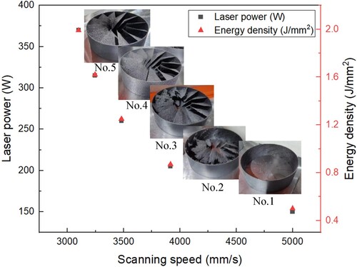
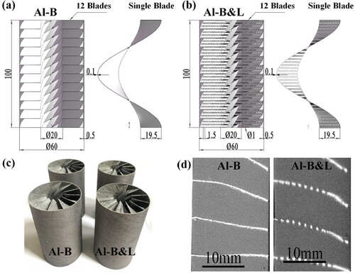
shows the fully dimensioned drawings and photographic images of the 3D-printed Al frameworks with porous Al blades, and the cross-sectional morphology after filling with paraffin propellant, respectively. An Al framework with multiple inner spiral blades was fabricated adopting SLM. The framework comprised an outer wall and 12 integrated blades spiralling in the axial direction. The length, outer diameter, and inner diameter of the fuel framework were 100, 60, and 20 mm, respectively. It should be noted that the breathable blades are created by manipulating the process parameter based on the drawings of Al-S, which is not from designed drawings. This is the main difference as compared to designed pores using lattice structures (Chua, Sing, and Chua Citation2023; Tan et al. Citation2022). Although the pores are uncertain before the process parameter is determined, the process parameter is controllable. This study used printing parameters of No.5 showed in with a power density of 1.99, and at least four repeatable Al frameworks with breathable blades were obtained. Commercial gas-atomised AlSi10Mg powder with a particle size of 15–53 µm was used as feedstock material. An SLM®125 machine from SLM Solutions Group AG was used to produce the Al frameworks. Laser powder bed fusion processing was performed under an argon atmosphere with the oxygen content maintained below ∼100 ppm. The building plate was preheated to 200°C. The layer thickness was kept constant at 60 µm.
Figure 2. The design drawings and photographic images of the 3D printed Al frameworks. (a) The fully dimensioned drawing of the Al-S framework. (b) The fully dimensioned drawing of the Al-L framework. (c) As-printed Al-B (left) and Al-B&L (right) frameworks. (d) The cross-sectional morphology after filling with paraffin propellant.
The morphology of the as-fabricated blades was observed adopting optical microscopy (OM, Axio Observer 3) after standard polishing. The internal pores were analysed through micro-focus computed tomography (micro-CT) using a ZEISE machine with W radiation at 210 kV and 30 µA. The pore size was measured from optical microscopy images following computer binarisation processing. The porosity of the blade was calculated using ImageJ software.
Finally, a centrifugal process cast the fully molten paraffin-based fuel into the Al framework until all the gaps between the Al blades were filled. During casting (centrifuge speed was set to 1400 rpm), the paraffin-based fuels were gradually added and adequately cooled each time to prevent internal cracks or defects and minimise thermal stress. The paraffin-based fuel consisted of 58 wt% paraffin (paraffin 58) together with 20 wt% polyethylene wax, 10 wt% Ethylene Vinyl Acetate, 10 wt% octadecanoic acid, and 2 wt% carbon black. More details on the manufacture composite grain can be found in previous publications (Lin et al. Citation2022; Luo et al. Citation2023; Wang et al. Citation2020; Zhang et al. Citation2022a).
2.2. Mechanical tests of composite fuel grains
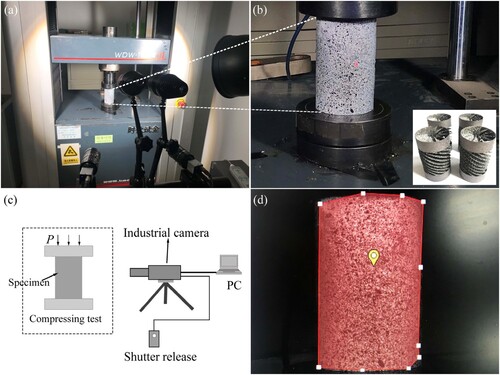
Uniaxial compression tests at ambient temperature on the 3D-printed Al nested composite fuel grains were conducted using an MTS810 universal testing machine. The compression rate was 1 mm/min.
To investigate the bonding strength of the interface between the porous Al blade and paraffine fuel, additional Al-B and Al-B&L frameworks without an outer shell were designed manufactured as shown in (b). After the transferring of paraffine, cyclic compression loading was performed on the composite fuel grains. shows the non-contact, full-field deformation and 3D strain measurement system used during cyclic loading. The low-speed industrial camera of HF Agile Device Co.Ltd. was used and the camera resolution is 2480*2048, as well as Lens focal length is 50 mm. A speckled pattern was sprayed onto the measured surface.
Figure 3. Strain measurement during the loading of Al-B and Al-B&L without an outer shell.
2.3. Laboratory-scale hybrid rocket engine
The laboratory-scale hybrid rocket engine used for combustion analysis is shown in and briefly described here. Further information on the apparatus can be found in our previous publication (Lin et al. Citation2022). The engine used oxygen gas as the oxidiser and a methane/oxygen torch activated by a spark plug to ignite the fuel grain. The mass flow rate of oxygen was set at 18.1 g/s using a calibrated mass flow controller (Bronkhorst, model F-203AV) in all firing tests. This rate corresponded to an average mass flux value of 5.77 g/(cm2·s). The combustion chamber had a length of 100 mm and inner diameter of 60 mm, which were consistent with the length and outer diameter of the fuel grain. Two pressure transducers sampling at a frequency of 1 kHz were placed in the pre- and post-combustion chambers of the motor. A single ultrasonic probe was located in a central position on the grain to measure the regression rate in real time. A conical nozzle having throat and outlet diameters of 5 and 10 mm respectively was used. The firing test conditions are summarised in .
Figure 4. Schematic of the experimental setup for the laboratory-scale hybrid rocket engine.
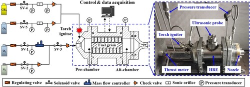
Table 1. Firing test conditions.
3. Results and discussion
3.1. Porous blade and pore formation mechanism
3.1.1. Pore characteristics
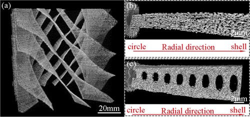
A multiscale structure of the Al framework was designed. This structure comprised a cylindrical shell and twelve helical blades of three types. shows the helical blades of Al-B and the microstructure of Al-B and Al-L observed by micro-computed tomography. The partial blade in (a) has the main characteristics of helical thin blades with obvious macroscopic interconnected pores. Image analysis reveals that the Al-B blade in (b) has micrometer-scale pores that vary gradually along the radial direction and have maximum porosity of 49.8% near the shell owing to the lower power density of the blade near the shell. (c) shows lattice elliptical pores of the Al-L blade, with the ratio of the length of the elliptical pore to the half-axis length increasing along the radial direction. The size of the elliptical pores in the Al-L blade increases along the radial direction, which decreases thermal conduction in this direction. In addition, an elliptical pore means that there is anisotropic thermal conduction that leads to thermal conduction along the radial direction being approximately 7% higher than that in the axial direction. In comparison with the Al-L blade, the Al-B&L blade has the same elliptical pores and breathable structure as the Al-B blade but in other parts of the blade.
Figure 5. Macrostructure and microstructure of (a,b) Al-B and (c) Al-L.
3.1.2. Factors that affect porosity
The pores size and porosity of the 3D printed structure mainly depends on the laser processing parameters. A 3D transient computational temperature fluid model (CtFD) and a powder-scale multiphysics dynamics model are developed to physically derive the relation between the present SLM process and the micrometer-scale interconnected-pore structure. The proposed computational model considers heat transfer, fluid flow, and the formation of the melt track. AlSi10Mg powders with a layer thickness of 53 µm and diameter range of 15–53 µm are randomly generated and filled into a powder bed with dimensions of 6.2 mm × 0.4 mm × 0.06 mm. It is noted that the model is much longer along the scanning direction than conventional SLM numerical models (Ge et al. Citation2021; Yan et al. Citation2017; Zhao et al. Citation2020) because the scanning speed is greatly increased in the present work to print a porous structure with excellent mechanical and combustion properties. A 3D powder-scale CtFD model is constructed and discretised using an orthogonal grid with consideration of the calculation efficiency and modelling accuracy. The total number of cells is 5,142,386 and the cell size is . The physical time is 2 ms and the minimum time step is
for the proposed model. Iterative calculations are made using the SIMPLE algorithm based on the finite volume method. A mesh-sensitivity test is preliminarily carried out by varying the cell size to exclude the effect of the mesh on the simulation resolution. Melt pool dynamics in SLM are modelled making some major assumptions. Marangoni convection inside the melt pool is Newtonian, laminar, and incompressible under the Boussinesq approximation. The laser heat source is Gaussian with a constant scanning speed. A porous medium flow is assumed in the mushy zone and described by the Carmen–Kozeny relation (Voller and Prakash Citation1987). The heat loss due to material evaporation is not considered.
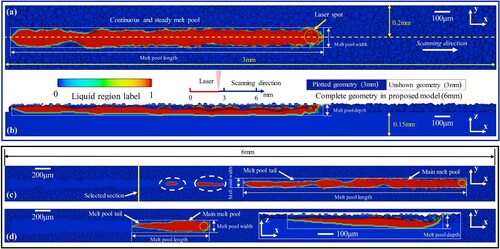
As shown in (a), a continuous and steady melt track is achieved for the parameters listed in and there are no defects such as balling or unevenness of the track boundary. The scanning speed is set as high as 3100 mm/s in this work to lower the energy density and thus construct a pore-through structure at micrometer. As a result, the melt pool length is much longer and there remains a liquid region even though the laser has swept a long distance (see (c)). Additionally, separate liquid regions without connection to the main melt pool are observed as indicated by the white dotted ellipse in (c). To provide a control group, modelling is carried out using conventional SLM parameters from the literature (Kan et al. Citation2021), and the simulated melt pool morphology and melt track are plotted in (d). Compared with the results in (c), the length of the melt pool achieved at a scanning speed of 500 mm/s is much smaller and there is no separate liquid region, but the width of the melt pool is obviously larger as shown in the inset of (d). Specifically, the width of the simulated melt pool is 120 µm for the conventional SLM (at 500 mm/s) and 158 µm for the ultra-high-speed SLM (at 3100 mm/s). The ultra-high scanning speed and lower heat input result in smaller (larger length and smaller width) melt pool dimension and separate liquid region in the printing of a breathable structure.
Figure 6. Melt pool morphology and melt track in the printing of a breathable structure. (a) Top view at a physical time of 0.6 ms. (b) Longitudinal view at a physical time of 0.6 ms. (c) Top view at a physical time of 1.8 ms. (d) Top and longitudinal views of the control group at a physical time of 5 ms. Colour contours represent the fraction of the liquid phase. The melt pool in the SLM process is indicated by the white dotted rectangle whereas the position of the laser spot is indicated by the yellow dotted circle. The scanning direction of the laser heat source is shown in (a) and is the same for the other sub-figures.
As discussed, there are some key factors that determine the final porosity distribution in the as-bulit part (Kuo et al. Citation2020; Li et al. Citation2018; Yu et al. Citation2019; Zhang et al. Citation2022b), involving the stress inside printed stucture, addition of Erbium (Er) element or Scandium (Sc) element to printing alloy, remelting of solidified parts, as well as the process-induced prosity, which is resulted the unexpected printing process such unstable keyhole or gas entrapment. The current study is focused on the the final process-induced prosity. Material evaporation induced keypore is not observed in the present modelling because the volume energy input is relative lower under the ultra-high scanning speed. Thus, the keyhole pores and trapped gas are not the mian causes for the existing pority, and the final porosity of the as-built burnable structure is expected to be resulted from lack of fusion, which is consistent with a conclusion given in the literature (Tang, Chris Pistoriusa, and Beut Citation2017); i.e. there tends to be a lack of fusion when the scanning speed is high and the energy input is low. The solidification rate of the liquid melt pool (i.e. the motion rate of the interface of the liquid and solid phases) has been shown to positively correlate to the speed of movement of the laser heat source (Li et al. Citation2020; Citation2022). Owing to the ultra-high speed of the laser in the present printing, the solidification rate is expected to be high. This is considered a benefit to the bubble–pore transition during the melting/solidification process (Yu et al. Citation2022). Pores existing in final solidified parts can be attributed to the rapid solidification of the melt pool without the complete filling of bubbles with liquid materials. Finally, four pores on the micrometer scale with a large dimension dispersion are observed. Pores reserved in the solidified track cannot be eliminated by the melting of the adjacent track or added layer (Zheng et al. Citation2019). At a constant laser power of 20 W, an increase in the scan speed increases the porosity. The porosity rose from 52% to 70% as the scan speed increased from 1000 to 2000 mm/s (Ho, Gibson, and Cheung Citation1999; Xie et al. Citation2013). More importantly, it is emphasised that porosity features, including the porosity amount and porosity dimension, may randomly differ at different positions and are reasonably expected to be affected by the laser power, scanning speed, powder laser thickness, powder diameter, apparent density, and printing toolpath. Porosity features will be further quantitatively modelled in future work considering all these key factors.
3.2. Effect of the porous blade on the interface bonding strength
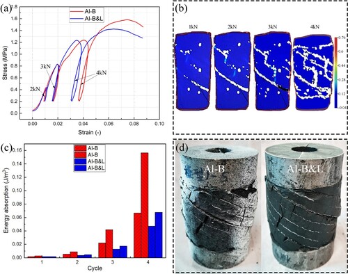
The composite fuel grain comprises Al and paraffine. There are two types of interface between two phases, the first interface being that between the outer shell and paraffine and the second interface being that between the blade and paraffine. To study the interfacial affect of composite fuel grains with breathable blades, cyclic compression tests are performed on the Al-B and Al-B&L grains without the first interface and the main results are shown in . (a) presents the stress–strain curves of Al-B. It is seen that the loading and unloading curves largely coincide at pressure of 2 kN. Nevertheless, the loading curves do not coincide with the unloading curves of 3 and 4 kN and do not form a closed loop. This is consistent with the true strain measurement made during loading as shown in (b), where the colour bar shows the magnitude of strain. With increasing pressure, there is first slight strain on the helical blade and then higher strain in the paraffine in the direction perpendicular to the blade. Cracking accompanies the high strains in these regions. The stress–strain curve and true strain measurement of Al-B&L have the same tendencies as those of Al-B, and there are two experiments for each blade. By integrating the stress–strain curve according to expression (1), the energy absorptions of Al-B and Al-B&L composite fuel grain are obtained as in (c). The energy absorption is the ability of the composite structure to absorb energy throughout the process from plastic deformation to fracture and is the comprehensive performance of strength and plasticity. The plastic strains of the Al-B and Al-B&L composite fuel grains increase with the cycle number (i.e. the pressure), and obvious plastic strain occurs when the pressure exceeds 0.8 MPa (a). In addition, the Al-B composite fuel grain has higher plastic strain capacity than the Al-B&L composite fuel grain.
(2)
(2) (d) shows photographs of fracturing after the loading of the Al-B and Al-B&L. The failure mode is consistent with the true strain measurement during loading, with there being delamination and fracturing in the region of maximum strain. Specifically, there are multiple delaminations on the interface between the helical blade and paraffine, mainly through-wall cracking and small cracks distributed in the paraffine with the special angle of the perpendicular direction to the blade. The pores provide excellent energy absorption and elastic recovery and strengthen interface bonding.
Figure 7. Cyclic loading of composite fuel grains with breathable blades: (a) stress–strain curve of Al-B and Al-B&L; (b) strain measurement during the loading of Al-B; (c) energy absorption of Al-B and Al-B&L; (d) photographs of fracturing after the loading of Al-B and Al-B&L.
3.3. Mechanical properties of the composite fuel grains
The mechanical properties of the 3D printed composite fuel grains were studied by conducting compression tests at room temperuture. The mechanical performance at elevated temeratures was discussed in the previous paper (Lin et al. Citation2022). All data are given in . Young’s modulus and the yield stress of the Al composite grains were much higher than those of the paraffin-based fuel grain. Specifically, Al-B had the highest Young’s modulus at more than 15 times that of the paraffin-based fuel grain, whereas Al-B&L had the highest yield stress at 4 times that of the paraffin-based fuel grain.
Table 2. Mechanical properties of the fuel grains at a compression rate of 1 mm/min and temperature of 293 ± 5 K.
Better mechanical properties of the Al nested composite fuel grain were observed in our previous work (Lin et al. Citation2022), which we hypothesise was due to the outer Al shell. shows that the mechanical properties of the three types of Al blade are different. To determine the respective effects of the outer Al shell and inner Al blades, the mechnical behaviour of the composite grain was investigated in a finite element analysis using the ABAQUS/Standard analysis module. The simulation focused on compression tests in investigating the stress field and possible locations of damage by replicating the operating conditions of the experimental part. The material constitutive model considers elasticity and plasticity and comprises solid elements of paraffin-based fuel and Al substrate. The contact surfaces of the fuel and substrate are bound by ‘tie’ in the interaction module. On the basis of actual measurements and results of true compression tests, the density, elastic modulus, and yield stress are set for the fuel and substrate. The neutral axis algorithm is used to divide the hexahedron mesh with a minimum mesh size of 125 µm × 250 µm and 357,061 nodes (i.e. C3D8R cells). The centre point on the upper surface of the model is selected as the reference point. The displacement of the reference point is controlled to realise the compression action. The displacement control speed is 1 mm/min. Fixed boundary conditions are set on the lower surface of the model.
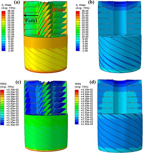
presents the main simulation results of the Al nested composite fuel grain. The von Mises stress and equivalent plastic strain (PEEQ) are extracted after post processing and displayed forthe Al shell and paraffine separately. For better comparison, the scale bars of the maximum von Mises stress and PEEQ are consistently set at 38 MPa and 0.057 separately. The simulation of the mechanical performance shows that the von Mises stress is a maximum at both ends of the Al shell and a minimum in the paraffine. In addition, the von Mises stress of the Al shell is greater than that of the Al blades, and the von Mises stress of the Al blades is greater than that of the paraffine. The von Mises stresses along two paths of Al blades are presented in (a). It is seen that the stress first decreases and then increases in the radial direction. In the axial direction, only half of the blade is considered as the blade is symmetric, and the stress in the middle part is seen to be greater than that at the ends. The PEEQ has the same distribution as the von Mises stress. The PEEQ is a maximum at the two ends of the Al shell. In the radial direction of the Al blade, the PEEQ first decreases and then increases. In addition, the PEEQ in paraffine is much less than that in Al, and the PEEQ is mostly in the middle of paraffine and at the ends. The above results are consistent with the fracture macrostructure of the composite grain. The ‘tie’ contact condition between Al blades and paraffine in the simulation means that there is an ideal interface. However, different blades have different interface bonding and variable mechanical properties in practical experiments.
Figure 8. Al nested composite fuel grain: (a, b) von Mises stress of the Al shell and paraffine; (c, d) equivalent plastic strain of the Al shell and paraffine.
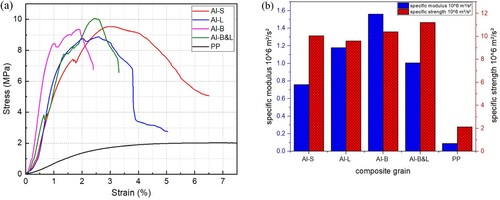
(a) compares the stress–strain curves of all the composite fuel grains. It is seen that the Al nested composite fuel grains behave more like a classic metal with obvious yield and strength, in contrast with PP grains. Comparing with Al-S with solid blades, Al-B with micrometer-scale pores has a 95.6% higher Young’s modulus and 1.6% lower yield stress, Al-L with millimetre-scale pores has a 50.9% higher Young’s modulus and 6.9% lower yield stress, and Al-B&L with multiscale pores has a 25.4% higher Young’s modulus and 5.6% higher yield stress. Owing to the different weight of blades, the specific modulus and specific strength are calculated and compared in (b). Al-B composite fuel grains have a higher specific modulus for maintaining specific strength that is comparable to that of Al-S. In addition, the specific strength of Al-B&L is higher than that of Al-L, whereas the specific modulus of Al-B&L is lower than that of Al-L. The Al blade with multiscale pores has a specific modulus lower than that of an Al blade with a single scale of pores but surprisingly the highest specific strength. Both the specific modulus and specific strength are much higher for Al-B&L than for Al-S. The overall mechanical properties are better for micrometer-scale pores, which is consistent with the cyclic loading results; i.e. micrometer-scale pores absorb more energy and have stronger interface bonding than multiscale pores.
Figure 9. Comparison of (a) stress–strain curves and (b) specific moduli and specific strengths for all composite fuel grains.
3.4. Combustion characteristics of the composite fuel grains
summarises data obtained in firing tests conducted in this study; i.e. the average combustion chamber pressure, Pc, burn time tburn, average oxygen mass flux Gave, average O/F values, average regression rate ṙave, and experimental characteristic velocity Ce*. The regression rate and combustion characteristic velocity are the two parameters most critical to hybrid rocket engines. The regression rate of the fuel grain refers to the speed at which the fuel surface burns back and is calculated as.
(3)
(3) where d0 and df are the average inner diameters of the fuel grain before and after the firing test, respectively. Here, df is calculated as
(4)
(4) where mf0 and mf are the masses of the fuel grain before and after the firing test, L is the length of the cylindrical fuel grain, and ρave is the average density of the fuel grain. The composite grain, ρave, is calculated as the average value for the two fuels:
(5)
(5) where ρAl and ωAl are respectively the density and mass fraction of the 3D printed Al blade and ρp and ωp are respectively the density and mass fraction of the nested paraffin-based fuel.
Table 3. Summary of firing test results.
The characteristic velocity is another important parameter for evaluating the combustion efficiency of an engine. The experimental characteristic velocity is calculated as.
(6)
(6) where At is the nozzle throat area and Ṁt is the mass of the oxidiser and fuel consumed.
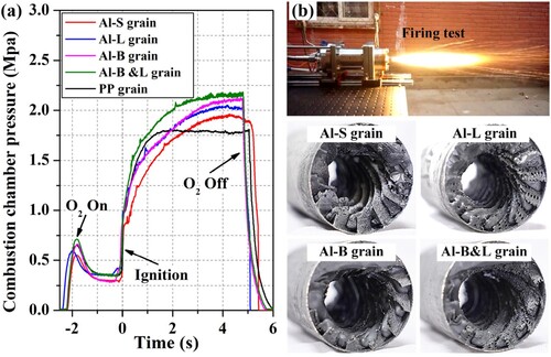
(a) plots the chamber pressure over time for all fuel tests. The timings of oxygen initiation and shutoff and engine ignition are given. The time at which the engine was initiated is taken as time zero. In all tests of the fuel grains, a quick ignition and stable combustion pressure were achieved. Notably, the shutoff for each test was not perfectly identical owing to delays in the valve response and control system command execution. (b) shows the composite fuel grains after the firing tests. It is clearly seen that grooves emerged between the Al blade and paraffin-based fuel, especially for the Al-S grain. This phenomenon is mainly due to the excellent thermal conductivity of the Al blade (approximately 2.5 orders of magnitude greater than that of paraffin), which accelerates the pyrolysis of the paraffin fuel in contact with the Al blade. The phenomenon is also affected by the inconsistent regression rate of the two fuels. Moreover, the inner surfaces of the Al-B and Al-B&L grains are more tightly bonded to the Al blades and paraffin-based fuel, which is attributed to the micrometer-scale pores and multiscale pores moderately reducing the difference in thermal conductivity and strengthening the bonding of the two fuels.
Figure 10. Laboratory-scale hybrid rocket engine static-fire test: (a) time histories of combustion chamber pressures and (b) inner surfaces of the composite fuel grains after testing.
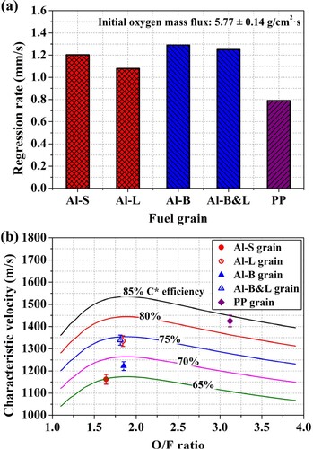
presents the regression rate and characteristic velocity of each fuel grain when using the same initial oxidiser mass flux. (a) shows that the regression rate is obviously higher for all composite grains than for the PP grain. For the Al-S, Al-L, Al-B, and Al-B&L grains, the regression rate was respectively 52.3%, 36.7%, 63.3%, and 58.2% higher than that of the PP grain. The millimetre-scale pores reduced the regression rate of the composite grains with different blade structures, such that the regression rate for Al-L was lower than that for Al-S and the regression rate for Al-B&L was lower than that for Al-B. The results are consistent with those of our previous work (Lin et al. Citation2022). Interestingly, the micrometer-scale pores increased the regression rate of the composite grains, such that the regression rate for Al-B was higher than that for Al-S and the regression rate for Al-B&L was higher than that for Al-L. As shown in (b), both the millimetre-scale and micrometer-scale pores increased the characteristic velocity of the composite grains, with the effect of the millimetre-scale pores being greater. The combustion efficiencies of the Al-L and Al-B&L fuel grains were approximately 14.9% and 9.6% greater than those of the Al-S and Al-B grains, respectively. This phenomenon can possibly be explained by the turbulence intensity increasement due to the millimeter-scale pores such that the combustion efficiency was increased. The experimental results reveal that the structure and proportion of blade pores create an inherent trade-off between the mechanical stability, regression rate, and combustion efficiency.
Figure 11. Comparison of (a) regression rates and (b) characteristic velocities for all composite fuel grains.
4. Conclusion
We obtained Al blades with millimetre-scale pores having excellent mechanical properties through the 3D printing of Al as the structural material of composite Al nested paraffin-based fuel grains. We further newly proposed an Al nested composite fuel grain with breathable blades designed with micrometer-scale interconnected pores. Achieving Al blades with micrometer-scale interconnected pores at the limitation of the blade thickness through 3D printing marks a breakthrough in manufacturing. The formation mechanism of the breathable blade is a lack of fusion at a super-high printing speed and low printing energy density. The mechanical and combustion properties of composite hybrid rocket fuel grains were investigated experimentally.
Al-B composite fuel grains with micrometer-scale pores had a 95.6% high specific modulus as they retained the specific strength properties of Al-S grains. In addition, the interconnected pores benefited paraffine fuel permeation and provided outstanding bonding strength between the Al blades and paraffine. Micrometer-scale pores improved the comprehensive mechanical properties, whereas multiscale pores structure improved the structural stiffness of the grain. Referring to combustion performance, millimetre-scale pores decreased the regression rate, micrometre-scale pores increased the regression rate, and multiscale pores increased the regression rate. Both millimetre-scale and micrometer-scale pores increased the characteristic velocity by 14.9% and 9.6%. However, this mechanism of enhanced combustion characteristics is not fully understood and more systematic studies, including theoretical work, 3D-printing process–structure relation analyses, and experimental analyses, are required.
Disclosure statement
No potential conflict of interest was reported by the author(s).
Additional information
Funding
References
- Armold, D. M., J. E. Boyer, B. McKnight, K. Kuo, J. Desain, B. B. Brady, J. Fuller, and T. J. Curtiss. 2014. “Testing of Hybrid Rocket Fuel Grains at Elevated Temperatures with Swirl Patterns Fabricated Using Rapid Prototyping Technology.” 50th AIAA/ASME/SAE/ASEE joint propulsion conference. https://doi.org/10.2514/6.2014-3754.
- Bisin, R., C. Paravan, S. Alberti, and L. Galfetti. 2020. “A New Strategy for the Reinforcement of Paraffin-Based Fuels Based on Cellular Structures: The Armored Grain — Mechanical Characterization.” Acta Astronautica 176: 494–509. https://doi.org/10.1016/j.actaastro.2020.07.003
- Bonatti, C., and D. Mohr. 2017. “Large Deformation Response of Additively-Manufactured FCC Metamaterials: From Octet Truss Lattices Towards Continuous Shell Mesostructures.” International Journal of Plasticity 92: 122–147. https://doi.org/10.1016/j.ijplas.2017.02.003
- Bonatti, C., and D. Mohr. 2019. “Mechanical Performance of Additively-Manufactured Anisotropic and Isotropic Smooth Shell-Lattice Materials: Simulations & Experiments.” Journal of the Mechanics and Physics of Solids 122: 1–26. https://doi.org/10.1016/j.jmps.2018.08.022
- Chan, T. Y., D. X. Wang, H. J. Chang, and C. L. Chen. 2007. “Fabrication of gas-Permeable Die Materials Having Orthogonally Arrayed Pore Channels.” Materials Science Forum 534-536: 961–964. https://doi.org/10.4028/www.scientific.net/MSF.534-536.961
- Chua, C., Swee Leong Sing, and C. K. Chua. 2023. “Characterisation of in-Situ Alloyed Titanium-Tantalum Lattice Structures by Laser Powder Bed Fusion Using Finite Element Analysis.” Virtual and Physical Prototyping 18 (1): e2138463. https://doi.org/10.1080/17452759.2022.2138463
- DeLuca, L. T., T. Shimada, V. P. Sinditskii, and M. Calabro. 2017. Chemical Rocket Propulsion. Switzerland: Springer International Publishing.
- Faenza, M., A. J. Boiron, B. Haemmerli, and C. J. Verberne. 2019. “The Nammo Nucleus Launch: Norwegian Hybrid Sounding Rocket Over 100 km.” AIAA Propulsion and Energy 2019 Forum. https://doi.org/10.2514/6.2019-4049.
- First test flight of PERUN rocket demonstrator. 2020. https://spaceforest.pl/first-test-flight-of-perun-rocket-demonstrator/.
- Ge, W. J., S. Han, S. J. Na, and J. Y. Hsi Fuh. 2021. “Numerical Modelling of Surface Morphology in Selective Laser Melting.” Computational Materials Science 186: 110062. https://doi.org/10.1016/j.commatsci.2020.110062
- Guo, Z. H., H. Tian, Z. S. Wang, X. Y. Meng, and G. B. Cai. 2022. “Numerical and Experimental Study on 95% Hydrogen Peroxide Catalytic Ignition of Hybrid Rocket Motors with HTPB-Based Aluminum Additive Fuel.” Acta Astronautica 195: 98–108. https://doi.org/10.1016/j.actaastro.2022.03.004
- Hill, C., C. C. McDougall, T. Messinger, and C. T. Johansen. 2019. “Modification of Paraffin-Based Hybrid Rocket Fuels Using Structural Lattices.” AIAA Propulsion and Energy 2019 Forum. https://doi.org/10.2514/6.2019-4191
- Ho, H. C. H., I. Gibson, and W. L. Cheung. 1999. “Effects of Energy Density on Morphology and Properties of Selective Laser Sintered Polycarbonate.” Journal of Materials Processing Technology 89-90: 204–210. https://doi.org/10.1016/S0924-0136(99)00007-2
- Ibrahim, Khairul Amilin, Billy Wu, and Nigel P. Brandon. 2016. “Electrical Conductivity and Porosity in Stainless Steel 316L Scaffolds for Electrochemical Devices Fabricated Using Selective Laser Sintering.” Materials & Design 106: 51–59. https://doi.org/10.1016/j.matdes.2016.05.096
- Kan, X. F., Y. J. Yin, D. C. Yang, Wei Li, and Jiquan Sun. 2021. “Micro Pool Characteristics of 316L and the Influence of Sulfur During SLM.” Optics & Laser Technology 142: 107136. https://doi.org/10.1016/j.optlastec.2021.107136
- Karabeyoglu, A., G. Zilliac, B. J. Cantwell, S. DeZilwa, and P. Castellucci. 2004. “Scale-up Tests of High Regression Rate Paraffin-Based Hybrid Rocket Fuels.” Journal of Propulsion and Power 20 (6): 1037–1045. https://doi.org/10.2514/1.3340
- Klahn, C., F. Bechmann, S. Hofmann, M. Dinkel, and C. Emmelmann. 2013. “Laser Additive Manufacturing of gas Permeable Structures.” Physics Procedia 41: 873–880. https://doi.org/10.1016/j.phpro.2013.03.161
- Koh, Hwee Kang, James Moo, Swee Leong Sing, and Wai Yee Yeong. 2022. “Use of Fumed Silica Nanostructured Additives in Selective Laser Melting and Fabrication of Steel Matrix Nanocomposites.” Materials 15 (5): 1869. https://doi.org/10.3390/ma15051869
- Kuo, C. N., Chee Kai Chua, P. C. Peng, Y. W. Chen, Swee Leong Sing, Sheng Huang, and Y. L. Su. 2020. “Microstructure Evolution and Mechanical Property Response via 3D Printing Parameter Development of Al–Sc Alloy.” Virtual and Physical Prototyping 15 (1): 120–129. https://doi.org/10.1080/17452759.2019.1698967
- Li, Z. Y., G. Yu, X. L. He, S. Li, and Z. Li. 2020. “Fluid Flow and Solute Dilution in Laser Linear Butt Joining of 304SS and Ni.” International Journal of Heat and Mass Transfer 161: 120233. https://doi.org/10.1016/j.ijheatmasstransfer.2020.120233.
- Li, Z. Y., G. Yu, X. L. He, C. Tian, S. Li, and H. Li. 2022. “Probing Thermocapillary Convection and Multisolute Dilution in Laser Welding of Dissimilar Miscible Metals.” International Journal of Thermal Sciences 172: 107242. https://doi.org/10.1016/j.ijthermalsci.2021.107242.
- Li, Yingli, Kun Zhou, Pengfei Tan, Shu Beng Tor, Chee Kai Chua, and Kah Fai Leong. 2018. “Modeling Temperature and Residual Stress Fields in Selective Laser Melting.” International Journal of Mechanical Sciences 136: 24–35. https://doi.org/10.1016/j.ijmecsci.2017.12.001
- Lin, X., D. D. Qu, X. D. Chen, Z. Z. Wang, J. X. Luo, D. D. Meng, G. L. Liu, K. Zhang, F. Li, and X. L. Yu. 2022. “Three-dimensional Printed Metal-Nested Composite Fuel Grains with Superior Mechanical and Combustion Properties.” Virtual and Physical Prototyping 17 (3): 437–450. https://doi.org/10.1080/17452759.2022.2035934
- Lu, G., J. Shen, W. Hou, D. Ruan, and L. Ong. 2008. “Dynamic Indentation and Penetration of Aluminium Foams.” International Journal of Mechanical Sciences 50 (5): 932–943. https://doi.org/10.1016/j.ijmecsci.2007.09.006
- Luo, Jiaxiao, Zelin Zhang, Xin Lin, Zezhong Wang, Wu Kun, Gongxi Zhou, Senhao Zhang, Fei Li, Xilong Yu, and Jie Wu. 2023. “Flame Dynamics in the Combustion Chamber of Hybrid Rocket Using Multiangle Chemiluminescence.” Journal of Propulsion and Power 39: 482–491. https://doi.org/10.2514/1.B38955.
- Maconachie, T., M. Leary, B. Lozanovski, X. Zhang, M. Qian, O. Faruque, and M. Brandt. 2019. “SLM Lattice Structures: Properties, Performance, Applications and Challenges.” Materials & Design 183: 108137. https://doi.org/10.1016/j.matdes.2019.108137
- Okninski, A., W. Kopacz, D. Kaniewski, and K. Sobczak. 2021. “Hybrid Rocket Propulsion Technology for Space Transportation Revisited – Propellant Solutions and Challenges.” FirePhysChem 1 (4): 260–271. https://doi.org/10.1016/j.fpc.2021.11.015
- Oztan, C., and V. Coverstone. 2021. “Utilization of Additive Manufacturing in Hybrid Rocket Technology: A Review.” Acta Astronautica 180: 130–140. https://doi.org/10.1016/j.actaastro.2020.11.024
- Oztan, C., E. Ginzburg, M. Akin, Y. Zhou, R. M. Leblanc, and V. Coverstone. 2021. “3D Printed ABS/Paraffin Hybrid Rocket Fuels with Carbon Dots for Superior Combustion Performance.” Combustion and Flame 225: 428–434. https://doi.org/10.1016/j.combustflame.2020.11.024
- Research Flights 2021 Virgin Galactic. 2021. https://www.virgingalactic.com/research/.
- Ruan, D., G. Lu, F. Chen, and E. Siores. 2002. “Compressive Behaviour of Aluminium Foams at low and Medium Strain Rates.” Composite Structures 57 (1-4): 331–336. https://doi.org/10.1016/S0263-8223(02)00100-9
- Ruan, D., G. Lu, L. S. Ong, and B. Wang. 2007. “Triaxial Compression of Aluminium Foams.” Composites Science and Technology 67 (6): 1218–1234. https://doi.org/10.1016/j.compscitech.2006.05.005
- Ruan, D., G. Lu, B. Wang, and T. Yu. 2003. “In-plane Dynamic Crushing of Honeycombs—a Finite Element Study.” International Journal of Impact Engineering 28 (2): 161–182. https://doi.org/10.1016/S0734-743X(02)00056-8
- Shen, J., G. Lu, and D. Ruan. 2010. “Compressive Behaviour of Closed-Cell Aluminium Foams at High Strain Rates.” Composites Part B: Engineering 41 (8): 678–685. https://doi.org/10.1016/j.compositesb.2010.07.005
- Shen, C., G. Lu, and T. Yu. 2013. “Dynamic Behavior of Graded Honeycombs – A Finite Element Study.” Composite Structures 98: 282–293. https://doi.org/10.1016/j.compstruct.2012.11.002
- Siddique, Shakib Hyder, Paul J. Hazell, Hongxu Wang, Juan P. Escobedo, and Ali A.H. Ameri. 2022. “Lessons from Nature: 3d Printed bio-Inspired Porous Structures for Impact Energy Absorption – A Review.” Additive Manufacturing 58: 103051. https://doi.org/10.1016/j.addma.2022.103051
- Tan, Shujie, Xi Zhang, Ziyu Wang, Liping Ding, Wenliang Chen, and Yicha Zhang. 2022. “Characterization of Triply Periodic Minimal Surface Structures Obtained Using Toolpath-Based Construction Design.” Materials Science in Additive Manufacturing 1 (3): 17. https://doi.org/10.36922/msam.30
- Tang, M., P. Chris Pistoriusa, and Jack L. Beut. 2017. “Prediction of Lack-of-Fusion Porosity for Powder bed Fusion.” Additive Manufacturing 14: 39–48. https://doi.org/10.1016/j.addma.2016.12.001
- Voller, V., and C. Prakash. 1987. “A Fixed Grid Numerical Modelling Methodology for Convection–Diffusion Mushy Region Phase-Change Problems.” International Journal of Heat and Mass Transfer 30 (8): 1709–1719. https://doi.org/10.1016/0017-9310(87)90317-6
- Wang, Y., S. Q. Hu, X. L. Liu, and L. L. Liu. 2022a. “Boundary Layer Combustion of HTPB/Paraffin Fuels for Hybrid Propulsion Applications.” Aerospace Science and Technology 129: 107850. https://doi.org/10.1016/j.ast.2022.107850
- Wang, Y., S. Q. Hu, X. L. Liu, and L. L. Liu. 2022b. “Regression Rate Modeling of HTPB/Paraffin Fuels in Hybrid Rocket Motor.” Aerospace Science and Technology 121: 107324. https://doi.org/10.1016/j.ast.2021.107324
- Wang, Z. Z., X. Lin, F. Li, J. L. Peng, Y. Liu, Z. L. Zhang, S. H. Fang, and X. L. Yu. 2021a. “Determining the Time-Resolved Mass Flow Rates of Hybrid Rocket Fuels Using Laser Absorption Spectroscopy.” Acta Astronautica 188: 110–120. https://doi.org/10.1016/j.actaastro.2021.07.028
- Wang, Z. Z., X. Lin, F. Li, and X. L. Yu. 2020. “Combustion Performance of a Novel Hybrid Rocket Fuel Grain with a Nested Helical Structure.” Aerospace Science and Technology 97: 105613. https://doi.org/10.1016/j.ast.2019.105613
- Wang, Z., X. Lin, F. Li, Z. L. Zhang, and X. L. Yu. 2021b. “Improving the Combustion Performance of a Hybrid Rocket Engine Using a Novel Fuel Grain with a Nested Helical Structure.” Journal of Visualized Experiments: JoVE 167: e61555. https://doi.org/10.3791/61555
- Wei, S. S., M. C. Lee, J. W. Huang, Y. Lu, C. H. Kang, S. T. Kao, S. J. Lu, et al. 2022. “Demonstration of Tethered Hovering Flight of HTTP-3AT Hybrid Rocket.” Acta Astronautica 191: 279–292. https://doi.org/10.1016/j.actaastro.2021.08.042
- Whitmore, S. A., Z. W. Peterson, and S. D. Eilers. 2013. “Comparing Hydroxyl Terminated Polybutadiene and Acrylonitrile Butadiene Styrene as Hybrid Rocket Fuels.” Journal of Propulsion and Power 29 (3): 582–592. https://doi.org/10.2514/1.B34382
- Xie, Fangxia, Xinbo He, Shunli Cao, and Xuanhui Qu. 2013. “Structural and Mechanical Characteristics of Porous 316L Stainless Steel Fabricated by Indirect Selective Laser Sintering.” Journal of Materials Processing Technology 213 (6): 838–843. https://doi.org/10.1016/j.jmatprotec.2012.12.014
- Yahaya, M., D. Ruan, G. Lu, and M. Dargusch. 2015. “Response of Aluminium Honeycomb Sandwich Panels Subjected to Foam Projectile Impact – An Experimental Study.” International Journal of Impact Engineering 75: 100–109. https://doi.org/10.1016/j.ijimpeng.2014.07.019
- Yan, W. T., W. J. Ge, Y. Qian, S. Lin, Z. Bin, G. J. Wagner, F. Lin, and W. K. Liu. 2017. “Multi-physics Modeling of Single/Multiple-Track Defect Mechanisms in Electron Beam Selective Melting.” Acta Materialia 134: 324–333. https://doi.org/10.1016/j.actamat.2017.05.061
- Yu, Wenhui, Swee Leong Sing, Chee Kai Chua, and Xuelei Tian. 2019. “Influence of Re-melting on Surface Roughness and Porosity of AlSi10Mg Parts Fabricated by Selective Laser Melting.” Journal of Alloys and Compounds 792: 574–581. https://doi.org/10.1016/j.jallcom.2019.04.017
- Yu, W., Z. Xiao, X. Zhang, Yetao Sun, Peng Xue, Shuai Tan, Yongling Wu, and Hongyu Zheng. 2022. “Processing and Characterization of Crack-Free 7075 Aluminum Alloys with Elemental Zr Modification by Laser Powder Bed Fusion.” Materials Science in Additive Manufacturing 1 (1): 4. https://doi.org/10.18063/msam.v1i1.4
- Zdybal, D., L. Pabarcius, A. Laczewski, B. Wyciszkiewicz, A. Zwolak, P. Slawecki, and M. Wyzlinski. 2021. “Investigation of FDM-Printed Open-Framework-Reinforced Helical PEWAX Grains as a Robust: High Regression Hybrid Rocket Fuel.” AIAA Scitech 2021 Forum. https://doi.org/10.2514/6.2021-1247
- Zeng, G. H., T. Song, Y. H. Dai, H. P. Tang, and M. Yan. 2019. “3D Printed Breathable Mould Steel: Small Micrometer-Sized, Interconnected Pores by Creatively Introducing Foaming Agent to Additive Manufacturing.” Materials & Design 169: 107693. https://doi.org/10.1016/j.matdes.2019.107693
- Zhang, Z. L., X. Lin, Z. Z. Wang, K. Wu, J. X. Luo, S. H. Fang, C. Y. Zhang, F. Li, and X. L. Yu. 2022a. “Effects of Swirl Injection on the Combustion of a Novel Composite Hybrid Rocket Fuel Grain.” Acta Astronautica 199: 174–182. https://doi.org/10.1016/j.actaastro.2022.07.027
- Zhang, Xuhui, Zhen Xiao, Wenhui Yu, C. Chua, Lihua Zhu, Zongshen Wang, Peng Xue, Shuai Tan, Yongling Wu, and Hongyu Zheng. 2022b. “Influence of Erbium Addition on the Defects of Selective Laser-Melted 7075 Aluminium Alloy.” Virtual and Physical Prototyping 17 (2): 406–418. https://doi.org/10.1080/17452759.2021.1990358
- Zhao, Y., K. Aoyagi, K. Yamanak, and Akihiko Chiba. 2020. “Role of Operating and Environmental Conditions in Determining Molten Pool Dynamics During Electron Beam Melting and Selective Laser Melting.” Additive Manufacturing 36: 101559. https://doi.org/10.1016/j.addma.2020.101559
- Zheng, M., L. Wei, J. Chen, Qiang Zhang, Chongliang Zhong, Xin Lin, and Weidong Huang. 2019. “A Novel Method for the Molten Pool and Porosity Formation Modelling in Selective Laser Melting.” International Journal of Heat and Mass Transfer 140: 1091–1105. https://doi.org/10.1016/j.ijheatmasstransfer.2019.06.038