
 ?Mathematical formulae have been encoded as MathML and are displayed in this HTML version using MathJax in order to improve their display. Uncheck the box to turn MathJax off. This feature requires Javascript. Click on a formula to zoom.
ABSTRACT
Large-scale short carbon fibre-reinforced silicon carbide (Csf/SiC) ceramic matrix composites (CMCs) have important applications in the field of aerospace engineering. This study proposed the use of material extrusion based additive manufacturing to fabricate large-scale Csf/SiC CMC preforms. In this paper, we determined how the key material extrusion parameters, including solid loading, nozzle diameter and layer height impact the stability of the additively manufactured Csf/SiC CMCs. The solid loading significantly influenced the stability of the Csf/SiC CMCs, and the slurry with 50 vol.% solid loading was better for additive manufacturing. The layer height played a significant role in the void formation in CMCs. It was appropriate for structure retention to set the layer height as 60–75% of the nozzle diameter. The effect of angle from vertical on the stability of out-of-plane structure was also investigated. When the angle was over 40o, the out-of-plane structure additively manufactured without supports tended to collapse. Large-scale Csf/SiC CMC preforms with out-of-plane structures were finally successfully fabricated. This study is believed to provide some fundamental understanding for the fabrication of large-scale fibre-reinforced ceramic matrix composites.
1. Introduction
With the rapid development of aerospace technology, the requirements for aircraft with high performance are becoming higher, which requires materials with light weight, high strength and high toughness [Citation1–3]. Carbon fibre-reinforced silicon carbide (Cf/SiC) ceramic matrix composites (CMCs) not only exhibit good mechanical properties but also have high heat resistance [Citation4–6]. In aircraft applications, large-scale CMC parts are commonly used. At present, the fabrication methods and process are the key to the practical application of the Cf/SiC CMCs. Traditional manufacturing methods of large-scale Cf/SiC CMC parts mainly include two steps: manufacturing of the CMC preform and fabrication of the CMC matrix. Typically, fibre weaving [Citation7], fibre acupuncture [Citation8] and fibre layup [Citation9] are applied to produce CMC preforms. Then, liquid silicon infiltration (LSI) [Citation10–12], precursor infiltration and pyrolysis (PIP) [Citation13,Citation14] and chemical vapour infiltration (CVI) [Citation15–17] are subsequently used to obtain CMC matrix. It is noted that the manufacturing of the CMC preforms is critically difficult. Shrinkage cavities, oxide notches and other defects can occur often in the product during the manufacturing of the CMC preforms. Besides, traditional manufacturing techniques of the CMC preforms are also complicated and the cost is high. It is deemed necessary to find and develop a novel and advanced manufacturing technique of CMC preforms.
Fortunately, an alternative to these traditional methods is additive manufacturing (AM) technology. Compared with continuous carbon fibres, short fibres are easier and cheaper to be used to prepare short carbon fibre-reinforced silicon carbide (Csf/SiC) CMC preforms by AM technologies. Up to date, many researchers have successfully additively manufactured Csf/SiC CMC preforms [Citation18–20]. Zhang et al. [Citation21] prepared Csf/SiC CMC preforms with high precision and complicated structure by digital light process based additive manufacturing. Zhu et al. [Citation22] used select laser sintering-based additive manufacturing to prepare near-shape Csf/SiC CMC preforms with high strength. Zhang et al. [Citation23] fabricated Csf/SiC CMC preforms with periodic structure by material extrusion-based additive manufacturing. Although vat polymerisation-based additive manufacturing is suitable to prepare small components with high precision, photosensitive resin removal and sintering will be a challenging task for large-scale components. It should be pointed out that the melting points of ceramics are too high for laser powder bed fusion-based additive manufacturing [Citation24,Citation25]. Most importantly, due to the large temperature gradient and thermal stress during the laser sintering process, it is easy to induce warping and cracks into the large-scale components [Citation26–28]. In the water-based material extrusion process, a high solid loading slurry containing small amounts of polymer is used. And the extrusion process only needs to be carried out at room temperature. Therefore, material extrusion-based additive manufacturing technology has great prospects in preparing large-scale Csf/SiC CMC preforms. However, at present, almost all researchers focus on the mechanical properties and the precision of Csf/SiC CMC preforms prepared by material extrusion-based additive manufacturing. In our previous works, we focused on the effect of short fibre content on the mechanical properties of Csf/SiC CMC preforms prepared by material extrusion [Citation29]. When preparing large-scale Csf/SiC CMC preforms, the printing and maintaining stability of a given large-scale structure is one of the key issues. Especially, many Csf/SiC CMC preforms have out-of-plane structure in engineering application. However, few developments have been made to print overhanging features without supports and structures on freedom surfaces for Csf/SiC CMC preforms. Until now, the fabrication of advanced ceramic with a thin-wall structure larger than 100 mm is scarcely reported.
In this paper, we prepared large-scale Csf/SiC CMC preforms with out-of-plane structure by material extrusion based additive manufacturing. We investigated the effects of solid loading and nozzle diameter on the geometry of filament such as shape, cross-sectional area. Further, we studied the effect of processing parameters during material extrusion on the stability of the given structure. Moreover, a large-scale Csf/SiC CMC preform was prepared on the base of the optimised processing conditions. This study is believed to provide some fundamental understanding for the fabrication of large-scale CMC preforms.
2. Experimental
2.1. Slurry preparation
The preparation of stable Csf/SiC slurries for material extrusion-based additive manufacturing involved three procedures. First, SiC powders (α-SiC, purity > 99.5%; d50 = 14.49 μm, Qinhuangdao ENO High-Tech. Material Development Co., Ltd., China), short carbon fibre (Csf, a diameter of 5–10 μm, a length of 30–60 μm, Qinhuangdao ENO High-Tech. Material Development Co., Ltd., China) and methyl cellulose (MC, 100000 mPa·s, Shanghai Macklin Biochemical Technology Co., Ltd., China) were mixed as premix powders. Then, polyethylene glycol (PEG6000, Xilong Chemical Co., Ltd., China) and distilled water were mixed as an aqueous solution. The premix powders were added into the aqueous solution. The as-obtained mixture was processed through ball milling in a planetary mill (QM-3SP2, Naijing University Instrument Plant, China) at a speed of 400 rpm for 3 h. Finally, a dispersed homogeneous Csf/SiC slurry was obtained. Here, three different Csf/SiC slurries with different solid loading were prepared, as listed in . The solid loading (containing SiC and Csf) of the Csf/SiC slurries was set as 40, 45 and 50 vol.%, respectively. Among each slurry, the volume ratio of SiC and Csf was set as 1.5:1. For simplicity, in this paper, the slurries and green parts contained 40, 45 and 50 vol.% solid loading were marked as 40-Csf/SiC, 45-Csf/SiC and 50-Csf/SiC, respectively.
Table 1. Compositions used for the Csf/SiC slurries.
2.2. Material extrusion
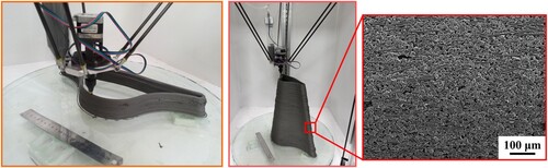
After preparing the well-dispersed Csf/SiC slurry, the slurry was transferred to the plastic syringe and the sample was built by a material extrusion based additive manufacturing system (Suzhou Fanbo Additive Manufacturing Technology Co., Ltd., China). The main section of the self-built additive manufacturing system was the material extrusion system which extruded composite slurry under the constructions of the computer and patterned the extruded filaments with the designed fashion. The whole printing process was taken place at room temperature, as shown in . After printing, the samples were dried at 100oC for 24 h. As shown in , the short carbon fibres were evenly dispersed in the green parts and maintain a cylindrical shape. The short carbon fibres were arranged along the printing direction.
Figure 1. Fabrication of Csf/SiC CMC preform by material extrusion based additive manufacturing.
2.3. Characterisation
Rheological behaviours of the Csf/SiC slurries were determined at room temperature using a rotational rheometer (Physical MCR301, Anton Parr Gmbh, Austria). Cross-sectional images of Csf/SiC CMC preforms were observed by optical microscope and macro camera.
In this paper, a concept of dimension deviation ratio (DDR) was used to quantify the dimensional accuracy of the Csf/SiC CMC preforms using the following equation:
(1)
(1) where X was the measured dimension using a digital caliper with an accuracy of 0.01 mm and X0 was the dimension of the designed CAD model.
3. Results and discussions
3.1. Effects of solid loading on Csf/SiC slurries
Flow curves demonstrating the dependence of viscosity and shear stress on applied shear rate for the Csf/SiC slurries with different solid loading are shown in . As shown in (a), viscosities of all Csf/SiC slurries decreased with the increase of shear rate. These flow curves revealed that all Csf/SiC slurries behaved in a yield-pseudoplastic manner. An increase in viscosity was observed for increasing the solid loading of Csf/SiC slurries, because of an increase in the inter-particle interactions and inter-particle collisions [Citation30]. (b) shows the dependence of shear stress on shear rate for the Csf/SiC slurries and it was obviously found that the increase in solid loading led to an increase in yield stress. As shown in (b), each curve was fitted to the Herschel–Bulkley model for yield-pseudoplastic materials, displayed in the following equation:
(2)
(2) where
(Pa) is the shear stress applied,
(Pa) is the yield stress, K (Pa·sn) is a consistency,
(s−1) is the shear rate and n is the flow index.
Figure 2. (a) Log viscosity versus log shear rate plots; (b) log shear stress versus log shear rate of varying Csf/SiC slurries with different solid loading.
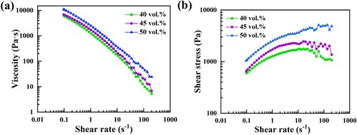
After fitting the curves using the Herschel–Bulkley model, the fitting parameters were obtained. And the 40-Csf/SiC, 45-Csf/SiC and 50-Csf/SiC slurries had the n values of 0.239, 0.212 and 0.217 respectively. All Csf/SiC composite slurries with n values of less than 1, which indicated a shear-thinning behaviour. Yield-pseudoplastic slurries are ideal raw materials for continuous material extrusion because they will flow in a shear thinning manner when an applied shear stress exceeds the yield stress and can retain the formed shape after extrusion [Citation31,Citation32]. The Csf/SiC slurries with 50 vol.% solid loading possessed the highest viscosity and yield stress. When the solid loading was higher than 50 vol.%, the Csf/SiC slurry become extremely viscous and lacked the fluidity. It was noted that all these Csf/SiC slurries were all suitable for the following material extrusion-based additive manufacturing.
3.2. Effects of solid loading and nozzle diameter on filament geometries
To investigate the effects of solid loading and nozzle diameter on filament geometries, an analysis was performed with cross-section area. shows the cross-sections of filaments under varying solid loadings and nozzle diameters (the printing height was larger than the nozzle diameter). It can be clearly seen that the solid loading greatly influenced the cross-sectional geometries of the extruded filaments. The flat top and wide shapes of the extruded filaments were commonly observed at low solid loading, whereas more semi-circular shapes can be seen at high solid loading. The explanation for flat top and wide shapes was that the shape retention correlates with yield stress and the slurry with relatively low solid loading possessed poor shape retention correspondingly, which resulted in the flat top and wide shapes. Under the same nozzle diameter, the cross-section area of filament decreased with the increase of the solid loading. The outline of the cross-section of 50-Csf/SiC filament was closer to the circle. All 50-Csf/SiC filament under varying nozzle diameters maintained the shapes well, indicating that the nozzle diameter had little effect on the extruded filament geometries when the solid loading was appropriate.
Figure 3. (a) Cross-section images of filament under varying solid loading and nozzle diameter; (b) outlines and areas of filament cross-sections under varying solid loading and nozzle diameters (simulated by ImageJ).
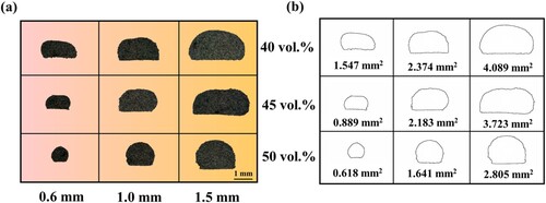
To better explain the influences of solid loading and nozzle diameter on the filament geometry, an analysis was performed with the measured line width and aspect ratio. shows the schematic of the measured line width of filaments. shows the measured line width of filaments. As shown in , the values of L1 of all filaments were larger than the nozzle diameter, indicating that the Csf/SiC slurry exhibited the expanding feature after the extrusion [Citation33]. With the increase of solid loading, the value of L1 became closer to the nozzle diameter. The value of L1 was bigger than the value of L2, because the collapse of the extruded filament. Compared with the nozzle diameter, the value of L1/L2 changed greatly with the solid loading. Under 50 vol.% solid loading, the value of L1/L2 was closer to 1.0, showing that the 50-Csf/SiC filaments possessed better shape stability.
Figure 4. The schematic of the measured line width of filaments.
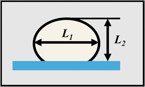
Table 2. The measured line width (mm) of filaments under varying solid loading and nozzle diameter.
3.3. Effects of printing parameters on thin wall geometries
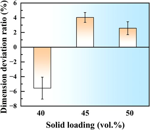
This section aimed to investigate the stability of layers during multilayer extrusion of Csf/SiC CMC preforms. During material extrusion, some drawbacks like collapse may occur and would damage the specimen quality, which are significantly dependent on the solid loading. shows the effects of solid loading on specimens with single filament plus multi-layer structure. As shown in (a), it was hard to differentiate between individual filament layers for the 40-Csf/SiC CMC preform. The collapse of 40-Csf/SiC CMC preform was also observed in (a), which caused specimens to shift in the vertical direction. The explanation for the collapse of 40-Csf/SiC CMC preform was that the shape retention correlates with the yield stress and the 40-Csf/SiC slurry with relatively low solid loading did not possess sufficient strength to support additional deposited layers, which resulted in the collapse during formation. As shown in (b) and (c), the 50-Csf/SiC CMC preform possessed better shape retention and the deviation in the plane direction was smaller, compared with the 45-Csf/SiC CMC preform specimen. shows the height deviation of specimens with single filament plus multi-layer structure under varying solid loading. The height deviation of the 40-Csf/SiC CMC preform was negative, while the height deviations of 45-Csf/SiC and 50-Csf/SiC CMC preforms were positive. The height deviation of 50-Csf/SiC CMC preform was only 2.58%. The increase of solid loading was conducive to reducing the dimension deviation of samples. Therefore, the 50 vol.% solid loading was better for the additive manufacturing of Csf/SiC CMC preform.
Figure 5. Images of specimens with single filament plus multi-layer structure under varying solid loading: (a) 40 vol.%; (b) 45 vol.% and (c) 50 vol.%. (nozzle diameter: 1.0 mm; layer height: 0.75 mm).
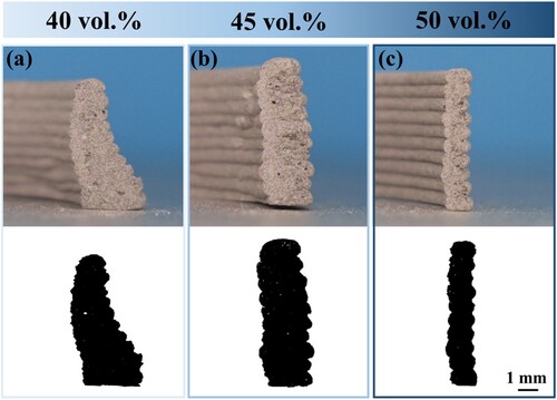
Figure 6. The height deviation of specimens with single filament plus multi-layer structure under varying solid loading.
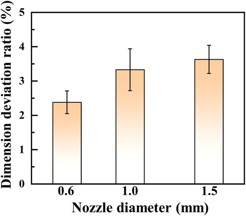
Upon the optimisation of the solid loading, the next step was focused on optimising nozzle diameter. Due to varying nozzle sizes, the flow velocity of inks during extrusion is different. As a result, the rebuilding time of the ink structure is also different, leading to different shapes of extruded filaments. shows the effects of nozzle diameter on specimens with two filaments plus multi-layer structure. As shown in , the nozzle diameter had an impact on the specimen structure quality. The cross-section of the 50-Csf/SiC CMC preform under a nozzle diameter of 0.6 mm was not regular, while the cross-section of 50-Csf/SiC structure under 1.0 mm nozzle diameter was close to rectangle, as shown in (a) and (b). The explanation for this phenomenon was that the 50-Csf/SiC slurry possessed relative high viscosity and the extrusion process might be discontinuous when printing under a small nozzle diameter, which led to uneven filament shape and ultimately affected the quality of the specimen structure. As shown in (c), the two filaments were no longer in the same horizontal plane after multi-layer deposition. shows the height deviation of 50-Csf/SiC specimens with two filaments plus multi-layer structure under varying nozzle diameter. All the height deviations of 50-Csf/SiC specimens under varying nozzle diameter were below 5%. The dimension deviation of samples decreased with the decrease of nozzle diameter. However, printing under too small nozzle diameter would lead to discontinuity or even blockage of filament extrusion. Therefore, when the nozzle diameter was 1.0 mm, it was better for the additive manufacturing of Csf/SiC CMC preform.
Figure 7. Images of 50-Csf/SiC specimens with two filaments plus multi-layer structure under varying nozzle diameter: (a) 0.6 mm; (b) 1.0 mm; and (c) 1.5 mm. (solid loading: 50 vol.%; layer height:75% of nozzle diameter).
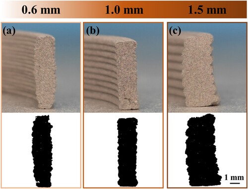
Figure 8. The height deviation of specimens with two filaments plus multi-layer structure under varying nozzle diameter.
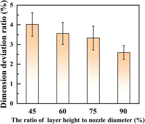
Upon the optimisation of the nozzle diameter, the next step was focused on optimising layer height. In this study, the layer height was determined by the nozzle diameter. The effect of layer height on 50-Csf/SiC specimens with two filaments plus multi-layer structure is shown in . As shown in , the transitions between individual layers were all clear. All the layer shapes were rounded rectangle. The arc angle increased with the increase of the layer height. As the decrease of the layer height, the inter-layer contact surface became bigger, which was conductive to improving the strength of Csf/SiC preforms and following composites [Citation34]. However, the extruded filaments were squeezed by nozzle and the deposited layers were compressed when the layer height was shortened to 45% of nozzle diameter, as shown in (a). shows the height deviation of 50-Csf/SiC specimens with two filaments plus multi-layer structure under varying layer height. As the increase of layer height, the dimension deviation of samples decreased. The heights of all samples under varying layer height were close to the set size, the height deviations were below 5%. When the layer height is smaller than 60% of the nozzle diameter, the extruded filaments should pile up rather than overlap. Therefore, it was appropriate to set the layer height at 60–75% of the nozzle diameter.
Figure 9. Images of 50-Csf/SiC specimens with two filaments plus multi-layer structure under varying layer height: (a) 45%; (b) 60%; (c) 75%; and (c) 90% of the nozzle diameter (1.0 mm).
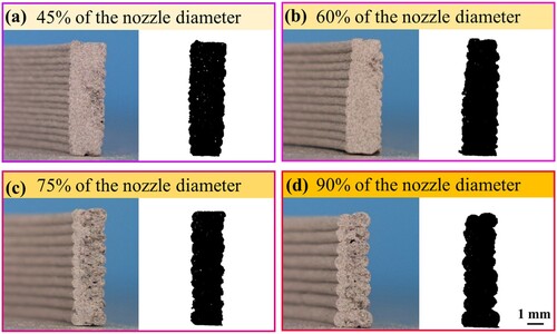
Figure 10. The height deviation of specimens with two filaments plus multi-layer structure under varying layer height.
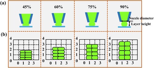
The effects of layer height on the sample fabrication are graphically shown in . As shown in (a), the filament shape changed from semi-rectangle to round as the increase of layer height, causing the layer shape to be rounded rectangle. The slurry was extruded out of the nozzle and the extruded composite slurry was unable to disperse, resulting in the distorted filament, when the layer height was 45% of the nozzle diameter. The top surface became poorer with the increase of layer height and the void area also increased as the layer height increased, as shown in (b).
Figure 11. (a) Schematic illustrations of extrusion process under various layer height and (b) schematic illustrations of the deposition of filament.
3.4. Manufacturing of large-scale Csf/SiC CMC preforms with out of plane structures
Based on the above results, the 50-Csf/SiC slurry was selected to prepare the out of plane structure, the nozzle diameter was 1.0 mm and the layer height was set to 75% of the nozzle diameter (0.75 mm). When additively manufacturing Csf/SiC CMC preforms, self-weight was a key factor affecting the stability of printed Csf/SiC slurries because they exhibited such low specific strength and stiffness. The characteristics of out of plane structures made them more unstable. Therefore, this section aimed to study the stability of preparing large-scale Csf/SiC CMC preform with out of plane structures by Csf/SiC slurries that relied solely on uncured rheological properties to support their own weight.
This study focused on the effects of α (the angle from the vertical, as shown in a) on the stability of Csf/SiC CMC preforms with out of plane structures. (b–f) show the printed walls with different angles from the vertical. As the increase of α, the contact area between the neighbour layers decreased, which might result in the collapse of Csf/SiC CMC preform structure. The top layer interface remained in the horizontal plane, when α was 10o, as shown in (b). As the increase of α, the top layer interface deflected. When α reached 45o, the top layer interface deflected by 38o and the Csf/SiC CMC preform structure collapsed catastrophically, as shown in (f). shows the α of idealised structure and the α of printed structure. When α was less than 40o, the printed structures were well matched with the designed structures and the angle deviation was less than 5o.
Figure 12. (a) The idealised wall; the printed walls with different angles from the vertical: (b) 10o; (c) 20o; (d) 30o; (e) 40o; (f) 45o. The top layer interface was marked in black. (solid loading: 50 vol.%; nozzle diameter: 1.0 mm; layer height: 0.75 mm).
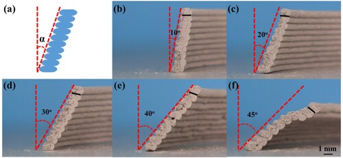
Table 3. The α of idealised structure and the α of printed structure.
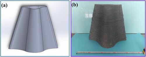
shows the morphology of large-scale Csf/SiC CMC preforms with out of plane structures. (a) shows that the solid works model of the out-of-plane structure. The α of the structure was about 20o and the height of the structure was 350 mm. As shown in (b), this Csf/SiC CMC preform structure was prepared without supports and the thickness of the structure was less than 6 mm. It was seen that the printed Csf/SiC CMC preform structure did not collapse, and was free of obvious defect or deformation. The outline of the Csf/SiC structure was stepped because of the layer-by-layer fabrication, which reduced the quality of the product. It is still an urgent and intractable challenge to develop a creative additive manufacturing technology that could fabricate large-scale components and control the forming accuracy simultaneously.
Figure 13. Images of large-scale Csf/SiC CMC preform with out of plane structure.
To sum up, this study only focused on the additive manufacturing of large-scale Csf/SiC CMC preforms. It is well known that the reinforcement effect of continuous fibres is much better than that of short fibres. However, the introduction of continuous fibres greatly increases the difficulty of fabrication. Currently, some researchers have tried to additively manufactured continuous fibre reinforced SiC ceramic matrix composites by material extrusion based AM technologies. Mei et al. [Citation35] reported the preparation method of a thermoplastic ceramic precursor feedstock which could be used to fabricate continuous carbon fibre reinforced SiC ceramic matrix composites by fused deposition modelling based additive manufacturing technique. Compared with fused deposition modelling, material extrusion used in this study was not a hot-melt extrusion technique method. Chen et al. [Citation36] modified a conventional nozzle system to print simultaneously a water-based SiC paste with continuous carbon fibres by material extrusion. During material extrusion, the poor impregnability of ceramic slurry made it difficult to fill the interior of fibre bundles, causing poor mechanical properties. Liu et al. [Citation37] introduced the ultrasound-assisted fibre separation technology to integrated fabricated continuous carbon fibre reinforced ZrB2-SiC composites by material extrusion combined with hot-pressing sintering. All in one word, additive manufacturing of large-scale continuous fibre-reinforced ceramic matrix composites will be an important direction in the future.
4. Conclusion
In summary, we reported a novel approach to fabricate large-scale Csf/SiC CMC preforms with out-of-plane structures by material extrusion based additive manufacturing technique. Csf/SiC slurries exhibited shear-thinning rheological behaviour and the viscosity increased with the increase of solid loading. The solid loading significantly influenced the stability of the printed Csf/SiC structures. Structures prepared by the Csf/SiC slurry containing 50 vol.% solid loading possessed sufficient strength to maintain designed structure during formation process. Compared with the solid loading, the nozzle diameter had little effect on the stability of the printed Csf/SiC structures. It was appropriate to set the layer height at 60–75% of the nozzle diameter, avoiding the distorted filament and reducing the void area between the filaments. The Csf/SiC CMC preform with out-of-plane structure can be fabricated by material extrusion without supports, when the angle from vertical was less than 40o.
Acknowledgement
R. He sincerely thanks the financial support from the National Natural Science Foundation of China [52275310] and the Foundation for the National Defense Key Laboratory [6142907210302]. G. Wang wants to thank the financial support from the National Natural Science Foundation of China [52171148, 51704001], the Natural Science Foundation of Anhui Province [2008085J23] and the Talent Project of Anhui Province [Z175050020001, gxyqZD2020059].
Disclosure statement
No potential conflict of interest was reported by the author(s).
Additional information
Funding
References
- Duan S, Matsuda K, Wang T, et al. Microstructures and mechanical properties of a cast Al–Cu–Li alloy during heat treatment procedure. Rare Met. 2021;40:1897–1906. doi:10.1007/s12598-020-01481-7
- Li W, Sun Y, Hu W, et al. Tribological properties of plasma-sprayed nickel alloy matrix self-lubricating coating at elevated temperatures. Rare Met. 2021;40:1844–1850. doi:10.1007/s12598-020-01426-0
- Li X, Yan L, Zhang Y, et al. Lightweight porous silica ceramics with ultra-low thermal conductivity and enhanced compressive strength. Ceram Int. 2022;48(7):9788–9796. doi:10.1016/j.ceramint.2021.12.180
- Zhao D, Guo T, Fan X, et al. Effect of pyrolytic carbon interphase on mechanical properties of mini T800-C/SiC composites. J Adv Ceramics. 2021;10(2):219–226. doi:10.1007/s40145-020-0432-3
- Wang J, Cao L, Zhang Y, et al. Effect of mass transfer channels on flexural strength of C/SiC composites fabricated by femtosecond laser assisted CVI method with optimized laser power. J Adv Ceram. 2021;10(2):227–236. doi:10.1007/s40145-020-0433-2
- Zhang Y, Zhang, Hu H, et al. Effect of the surface microstructure of SiC inner coating on the bonding strength and ablation resistance of ZrB2-SiC coating C/C composites. Ceram Int. 2016;42(16):18657–18665. doi:10.1016/j.ceramint.2016.09.003
- Li Y, Xiao P, Li Z, et al. Tensile fatigue behavior of plain-weave reinforced Cf/C-SiC composites. Ceram Int. 2016;42(6):6850–6857. doi:10.1016/j.ceramint.2016.01.068
- Ni Y, Luo R, Luo H. Fabrication and mechanical properties of 3-D Cf/C-SiC-TiC composites prepared by RMI. J Alloys Compd. 2019;798:784–789. doi:10.1016/j.jallcom.2019.05.197
- Zhang L, Chen Y, He R, et al. Bending behavior of lightweight C/SiC pyramidal lattice core sandwich panels. Int J Mech Sci. 2020a;171:105409. doi:10.1016/j.ijmecsci.2019.105409
- Shi Y, Kessei F, Friess M, et al. Characterization and modeling of tensile properties of continuous fiber reinforced C/C-SiC composite at high temperatures. J Eur Ceram Soc. 2021;41(5):3061–3071. doi:10.1016/j.jeurceramsoc.2020.09.043
- Zhang K, Guo X, Cheng Y, et al. TEM study on the morphology and interface microstructure of C/C-SiC composites fabricated by liquid infiltration. Mater Charact. 2021;175:111055. doi:10.1016/j.matchar.2021.111055
- Duan J, Li Y, Li F, et al. Corrosion behavior of LSI-based 3D needled C/SiC composites subjected to burner rig test. Corros Sci. 2022;197:109982. doi:10.1016/j.corsci.2021.109982
- Patra N, Al Nasiri N, Jayaseelan DD, et al. Thermal properties of Cf/HfC and Cf/HfC-SiC composites prepared by precursor infiltration and pyrolysis. J Eur Ceram Soc. 2018;38(5):2297–2303. doi:10.1016/j.jeurceramsoc.2017.12.051
- Yang L, Liu H, Zu M. Enhanced microwave-absorbing property of precursor infiltration and pyrolysis derived SiCf/SiC composites at X band: Role of carbon-rich interphase. J Am Ceram Soc. 2018;101(8):3402–3413. doi:10.1111/jace.15506
- Wang J, Cao LY, Liu YS, et al. Fabrication of improved flexural strength C/SiC composites via LA-CVI method using optimized spacing of mass transfer channels. J Eur Ceram Soc. 2020;40(8):2828–2833. doi:10.1016/j.jeurceramsoc.2020.02.050
- Wang J, Zhang Y, Liu Y, et al. Effect of initial density during laser machining assisted CVI process and its influence on strength of C/SiC composites. Ceram Int. 2020;46(8):11743–11746. doi:10.1016/j.ceramint.2020.01.207
- Luan X, Wang L, Zou Y, et al. Oxidation behavior of C/SiC-SiBCN composites at high temperature. J Eur Ceram Soc. 2019;39(10):3003–3012. doi:10.1016/j.jeurceramsoc.2019.04.025
- Fu H, Zhu W, Xu Z, et al. Effect of silicon addition on the microstructure, mechanical and thermal properties of Cf/SiC composite prepared via selective laser sintering. J Alloys Compd. 2019;792:1045–1053. doi:10.1016/j.jallcom.2019.04.129
- Franchin G, Wahl L, Colombo P. Direct ink writing of ceramic matrix composite structures. J Am Ceram Soc. 2017;100(10):4397–4401. doi:10.1111/jace.15045
- Lv X, Ye F, Cheng L, et al. Fabrication of SiC whisker-reinforced SiC ceramic matrix composites based on 3D printing and chemical vapor infiltration technology. J Eur Ceram Soc. 2019;39(11):3380–3386. doi:10.1016/j.jeurceramsoc.2019.04.043
- Zhang H, Yang Y, Hu K, et al. Stereolithography-based additive manufacturing of lightweight and high-strength Cf/SiC ceramics. Addit Manufac. 2020;34:101199. doi:10.1016/j.addma.2020.101199
- Zhu W, Fu H, Xu Z, et al. Fabrication and characterization of carbon fiber reinforced SiC ceramic matrix composites based on 3D printing technology. J Eur Ceram Soc. 2018;38(14):4604–4613. doi:10.1016/j.jeurceramsoc.2018.06.022
- Zhang H, Yang Y, Liu B, et al. The preparation of SiC-based ceramics by one novel strategy combined 3D printing technology and liquid silicon infiltration process. Ceram Int. 2019;45:10800–10804. doi:10.1016/j.ceramint.2019.02.154
- Wu S, Yang L, Wang C, et al. Si/SiC ceramic lattices with a triply periodic minimal surface structure prepared by laser powder bed fusion. Add Manufac. 2022;56:102910. doi:10.1016/j.addma.2022.102910
- Kuo C, Chua C, Peng P, et al. Microstructure evolution and mechanical property response via 3D printing parameter development of Al–Sc alloy. Virtual Phys Prototyp. 2020;15(1):120–129. doi:10.1080/17452759.2019.1698967
- Zhang X, Xiao Z, Yu W, et al. Influence of erbium addition on the defects of selective laser-melted 7075 aluminium alloy. Virtual Phys Prototyp. 2022;17(2):406–418. doi:10.1080/17452759.2021.1990358
- Li Y, Zhou K, Tan P, et al. Modeling temperature and residual stress fields in selective laser melting. Int J Mech Sci. 2018;136:24–35. doi:10.1016/j.ijmecsci.2017.12.001
- Yu W, Sing S, Chua C, et al. Influence of re-melting on surface roughness and porosity of AlSi10Mg parts fabricated by selective laser melting. J Alloys Compd. 2019;792:574–581. doi:10.1016/j.jallcom.2019.04.017
- Wang W, Bai X, Zhang L, et al. Additive manufacturing of Csf/SiC composites with high fiber content by direct ink writing and liquid silicon infiltration. Ceram Int. 2022;48(3):3895–3903. doi:10.1016/j.ceramint.2021.10.176
- Channell GM, Zukoski CF. Shear and compressive rheology of aggregated alumina suspensions. AIChE J. 1997;43:1700–1708. doi:10.1002/aic.690430707
- Costakis WJ, Reschhoff LM, Diaz-Cano AI, et al. Additive manufacturing of boron carbide via continuous filament direct ink writing of aqueous ceramic suspensions. J Eur Ceram Soc. 2016;36(14):3249–3256. doi:10.1016/j.jeurceramsoc.2016.06.002
- Lewis JA, Smay JE, Stuecker J, et al. Direct ink writing of three-dimensional ceramic structures. J Am Ceram Soc. 2006;89:3599–3609. doi:10.1111/j.1551-2916.2006.01382.x
- Xiong H, Zhao L, Chen H, et al. 3D SiC containing uniformly dispersed, aligned SiC whiskers: Printability, microstructure and mechanical properties. J Alloys Compd. 2019;809:151824. doi:10.1016/j.jallcom.2019.151824
- Googan TJ, Kazmer DO. Prediction of interlayer strength in material extrusion additive manufacturing. Addit Manuf. 2020;35:101368. doi:10.1016/j.addma.2020.101368
- Mei H, Yan Y, Feng L, et al. First printing of continuous fibers into ceramics. J Am Ceram Soc. 2019;102(6):3244–3255. doi:10.1111/jace.16234
- Chen R, Bratten A, Rittenhouse J, et al. Additive manufacturing of continuous carbon fiber-reinforced SiC ceramic composites with multiple fiber bundles by an extrusion-based technique. Ceram Int. 2023;49(6):9839–9847. doi:10.1016/j.ceramint.2022.11.157
- Liu Y, Cheng Y, Ma D, et al. Continuous carbon fiber reinforced ZrB2-SiC composites fabricated by direct ink writing combined with low-temperature hot-pressing. J Eur Ceram Soc. 2022;42(9):3699–3707. doi:10.1016/j.jeurceramsoc.2022.03.045.