
 ?Mathematical formulae have been encoded as MathML and are displayed in this HTML version using MathJax in order to improve their display. Uncheck the box to turn MathJax off. This feature requires Javascript. Click on a formula to zoom.
ABSTRACT
The critical role that numerical simulation plays in additive manufacturing has stimulated research on the effectiveness and potential applications of mesh-free, particle-based discretisation techniques. These methods excel at handling fluid flows and are viable alternatives to the mesh-based techniques typically used in commercial simulation software. In this paper, we review recent advances in developing computational models for metal additive manufacturing (MAM) processes using particle methods, in the theoretical understanding of the fundamental mechanisms that control such processes at the powder (or melt pool) scale, and in the predictability of physics-based modelling approaches. The paper explores the applicability and performance of particle-based methods in simulating powder bed fusion, directed energy deposition, and binder jetting processes. Since the progress of MAM relies on systematic material-process-structure realisations which are often impossible to sense or observe experimentally, developing efficient particle-based and multiscale simulation tools can be essential to achieving this objective through in-situ process control and optimisation.
1. Introduction
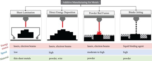
With more companies embracing Industry 4.0 worldwide, additive manufacturing (AM) and its Digital Twin representations will have an ever-expanding role in the research and development sector. American Society for Testing and Materials (ASTM) defines AM as one of the three major manufacturing techniques used to produce metallic or non-metallic components from an input CAD file via adding feedstock material layer-by-layer [Citation1, Citation2]. Processes in metal AM, henceforth MAM, are classified according to the source of the energy (i.e. laser, electron beam, or electric arc) and the form of the metallic material (i.e. powder or wire). shows a schematic illustration of four MAM modalities, among which Powder Bed Fusion (PBF) and Direct Energy Deposition (DED) are more common [Citation3, Citation4].
Figure 1. Additive manufacturing processes for metals and their basic features.
Many of the world's largest manufacturing companies, including Toyota, General Electric, Airbus, and Boeing, have recently begun using MAM as integral parts of their business and product developments [Citation5–7]. As a result of this momentum, the MAM market size has grown substantially within the past 9–10 years. The number of metal 3D printers sold in 2013 was about 300 worldwide, according to [Citation8], which increased to above 1800 machines in 2018. Despite this overwhelming investment and ever-growing share of interest in MAM, these technologies are still far from widespread industrial adoption. Uncertainty about the quality of the final product is perhaps the most critical and serious hurdle to this technology transition - see [Citation9, Citation10] for more insights. The key challenges are:
Over 100 parameters can affect the process and fabrication quality [Citation11].
Physical phenomena governing the build process are complex and cover a large range of time and length scales.
Formation of defects is generally inevitable due to our limited knowledge about the process details.
Relying on experimental trial-and-error procedures to find parameters for optimum part quality is an obvious but costly and, in many cases, impractical or impossible solution. Numerical modelling of MAM processes is a more flexible and efficient alternative that can help resolve these challenges. The immediate goals are to understand the sensitivity of part properties to process parameters and predict the thermo-mechanical behaviour of the final part to be able to choose optimal processing parameters without conducting a series of trial-and-error experiments.
Developing computational models for MAM is an active research area being pursued intensively by numerous institutions. The target application of these models varies from microstructure evolution [Citation12, Citation13] and melt pool behaviour [Citation14, Citation15] to residual stresses [Citation16, Citation17] and crack propagation [Citation18], depending on their study scale and the physics they implement. The quantity and diversity of MAM simulation works are overwhelming, which has led to a steady stream of review articles on this topic published within the past few years. Although mainly centred around their own developments, King et al. [Citation4, Citation9] were perhaps the first who classified and reviewed MAM simulation challenges systematically and described the multiscale modelling strategy in some detail. About a year later, Markl and Körner [Citation19] published a comprehensive review that elaborated different modelling approaches for PBF processes without delving into the mathematical background and equation systems. A new model classification was suggested in a 2017 review paper by Meier et al. [Citation20], where overall MAM simulations were divided into micro-, meso-, and macro-scale studies based on their length scale. The vast majority of relevant works, including the present review paper, follow this categorical definition. A few other surveys focussing on the general aspects of MAM modelling [Citation21, Citation22], the application of FEM (finite element method) to macroscopic PBF analyses [Citation23], and different multiphysics modelling strategies across scales [Citation24] were also carried out between 2017 and 2021. More recently, Li et al. [Citation25] presented coverage of models for the numerical simulation of powder recoating and melt pool dynamics in PBF.
Almost all existing MAM reviews, including the references given above, provide useful information by presenting a summary and catalog of published works that categorise different modelling strategies and simulation activities. For instance, Wei et al. [Citation22, Citation24] provided a large number of handy tables and literature listings (e.g. 77 figures and over 580 references cited only in [Citation22]) that covers a complete overview of the whole subject. In this sense, the reviews of Lou and Zhao [Citation23] and Cook and Murphy [Citation27] appear to be the only papers devoted to either a particular type of numerical technique (i.e. FEM) or a specific problem in MAM (i.e. melt pool behaviour) with sufficient technical details, respectively.
Overall, extensive review articles seem to have followed the rapid pace of MAM model developments and computing power advancements. Nonetheless, there is currently a lack of reviews on the application of particle-based numerical methods in MAM simulations. Therefore, it is necessary to provide a comprehensive overview of the current state of the art in this area, identify the technical challenges and opportunities in greater depth, and pave the way for future research in this exciting field. Our review aims to do just that–to research new improvement potentials for developing more efficient particle-based simulation tools and put them onto the path to compete with commercial codes in solving real-world MAM problems. We set our sights on modelling the powder-based MAM processes, namely PFB and DED (), using mesh-free particle methods, focussing on their technical merits and drawbacks when applied to the multiphase thermal-fluid flow problems encountered in MAM at the powder scale. These two processes share fundamental similarities in their modelling aspects and are more widely used than other MAM processes like binder jetting (BJ), thus chosen for the critical review here. For completeness, however, a brief mention of current BJ simulation approaches is given without detailing their theoretical background and modelling requirements.
Figure 2. Schematic representation of a PBF and a co-axial DED process. Courtesy of Dr. Florian Wirth for the experimental images taken at the Institute of Machine Tools & Manufacturing at ETH Zurich [Citation26].
![Figure 2. Schematic representation of a PBF and a co-axial DED process. Courtesy of Dr. Florian Wirth for the experimental images taken at the Institute of Machine Tools & Manufacturing at ETH Zurich [Citation26].](/cms/asset/e936184b-b950-4ebb-adb5-8ad21b7b0858/nvpp_a_2274494_f0002_oc.jpg)
We structure the rest of this manuscript as follows. In Section 2, the physical background and governing equations are described in some detail necessary to understand the requirements and challenges for modelling MAM processes. Section 3 gives a brief introduction of the particle-based techniques commonly used in MAM, reviews the published works employing these methods, and elaborates on their simulation capabilities and limitations. In Section 4, limitations of current approaches and potential pathways for further developments are discussed critically. We close the paper by outlining the key findings of this survey and summarising the most salient opportunities for further research directions in Section 5.
2. MAM simulation theory
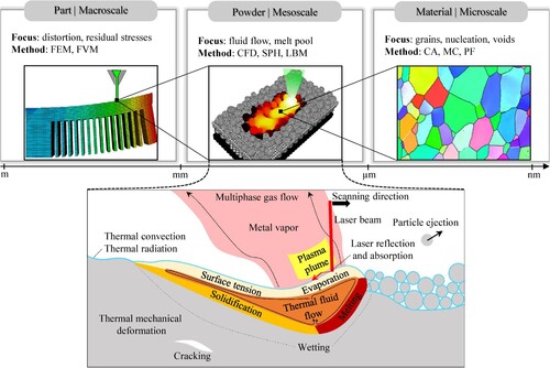
The physical phenomena during MAM occur at a wide range of time and length scales. Fabrication and heat treatment can easily take minutes or hours, while the laser-material interaction time is usually not longer than several micro- or milliseconds. Residual stress analysis might be carried out on fabricated components as large as a few meters, whereas the laser penetration depth is within the range of nanometers. Realizing the interplay between these complex effects warrants multiscale modelling. Nevertheless, due to the extreme computational demands of multiscale modelling approaches, it is practical (hence more common) to isolate the effects at an individual scale and utilise an efficient method for modelling them at that specific scale. For instance, FEM is currently considered the standard approach for analysing the residual stresses and mechanical deformations at the scale of the part–see [Citation19, Citation24]. The illustration in gives a graphical summary of these descriptions and their consequent mechanisms in a powder-based MAM example, representing the main physical phenomena to be addressed by a high-fidelity numerical modelling approach.
Figure 3. Different scales of study in modelling MAM processes (top) and the fundamental physical phenomena occurring in and around the melt pool region at the scale of the powder (bottom).
2.1. Underlying physics and governing equations
The local PBF and DED processes can be viewed as an extreme thermally-driven material transformation problem with complex boundary conditions, as illustrated in at the powder scale. Formulation of this initial boundary value problem begins with an expression to describe the interaction between the external heat source (i.e. laser or electron beam) and material. The energy is partially absorbed by the material and transferred via conduction, convection, and radiation. Parts of the energy not absorbed by the material are reflected at the surface and returned to the environment. As the beam traverses, it provides sufficient heat to melt the powder particles along the scanning path and creates a liquid melt pool that eventually solidifies. The input energy is typically high enough to vaporise the uppermost layer and generate a gas flow above the liquid surface.
As seen in , the melt pool behaviour is affected by numerous thermo-hydrodynamic effects such as heat transfer, surface tension, viscosity, wetting, Marangoni convection, and recoil pressure. Rapid phase changes occur at the solid-liquid interface, giving rise to the reformation of grain boundaries as a function of the cooling rate [Citation28]. As mentioned by Gu et al. [Citation29], mechanical failure like cracking () can occur as a result of significant thermal/residual stresses and extreme cooling rates on the order of K/s.
This process description clarifies why modelling PBF and DED with high fidelity necessitates a multi-phase multi-physics approach that incorporates various metallurgical, thermal, and mechanical effects. In what follows, we briefly revisit the fundamental balance equations (i.e. mass, momentum, and energy) governing the mesoscopic physics of the process as a prerequisite to numerical modelling. The microscopic issues, however, are excluded from the discussion as mesoscale simulation approaches do not take them into account.
2.1.1. Mass and momentum conservation
To represent the melt pool dynamics in MAM, it is usually assumed that the liquid is incompressible and the liquid pool is in a laminar flow regime. As a result of this simplification, the standard Navier–Stokes equations for mass and momentum conservation in a Lagrangian frame arrive at the following PDEs: (1)
(1)
(2)
(2) where
maintains the incompressibility condition, ρ is the density,
the velocity vector, p the pressure, μ the dynamic (shear) viscosity,
the acceleration due to gravity, and
any other volumetric body forces. To complete the momentum balance in Equation (Equation2
(2)
(2) ), the following effects need to be taken into account.
Surface tension
Surface tension and thermo-capillary forces, including the Marangoni convection, are exerted on the melt surface as a traction boundary condition. These forces are critical elements for modelling MAM as they significantly affect the geometry of the melt pool. See [Citation30] for the experimental evidence. Depending on the numerical technique employed for modelling MAM, various mathematical forms exist for expressing the contribution of surface tension to the momentum balance. The mathematical form expressed below is the most popular/fundamental one found in the literature. Following a continuum surface force (CSF) formulation proposed by Brackbill et al. [Citation31], the normal and tangential surface tension forces can be transformed into a volume force representation and expressed as:
(3)
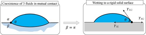
Wetting
The wetting ability of metals is key to obtaining a smooth surface for stable melt pools. Since processed layers in MAM are solid, co-existence of three fluid phases in mutual contact can be simplified to planar geometry, where one of the fluid phases is replaced by a flat rigid surface. See . This simplification is known as Young's relation [Citation32], which allows us to rewrite the net force equilibrium equation as:
Recoil pressure
The recoil pressure induced by the evaporation process occurring at the surface of a melt pool is the dominant mechanism of keyhole generation during laser-metal processing. Semak and Matsunawa [Citation33] demonstrated this behaviour by performing a theoretical analysis. Klassen et al. [Citation34] provided detailed descriptions of recoil pressure, which, although presented for electron beam melting applications, set the basis for (re-)adoption in other similar processes. In order to account for this substantial effect within the numerical modelling framework, an additional force needs to be included in the balance of momentum as the contribution of the recoil pressure term,
Figure 4. Schematic of Young's relation: simplification to planar geometry in wetting surfaces.
2.1.2. Energy conservation
MAM processes are essentially a thermally-driven problem. Therefore, it makes sense to express the system's energy conservation in terms of heat transfer. A complete representation of the thermal field contains all the external thermal powers, including the mechanical heating power. Since the spherical component of the stress power for incompressible materials is zero, the mechanical heating power consists only of a viscous heating term induced by the shear stress . The final heat transfer PDE to be solved becomes:
(7)
(7) where
is the specific heat capacity, k the thermal conductivity, and
the input thermal energy generated by a laser (or electron) beam, which can be expressed by:
(8)
(8) if α indicates the absorption coefficient and I the intensity. In most cases, the intensity of the laser in the radial direction is computed from a normalised Gaussian distribution as:
(9)
(9) with
indicating the laser power and R the laser beam radius. Several models with different levels of complexity exist to describe the correlation between the laser intensity and the penetration depth z. A popular choice is to exponentially decrease the absorptivity when the penetration depth increases by following the Beer-Lambert attenuation law:
(10)
(10) where L is the powder layer thickness and β the extinction coefficient, often taken as a constant value according to [Citation37]. The term
in Equation (Equation7
(7)
(7) ) is the environmental heat loss via radiation and convection given by:
(11)
(11) in which
is the heat convection coefficient, ϵ the emissivity factor, σ the Stefan–Boltzmann constant, and
and
are the surface and background temperatures.
2.1.3. Phase change
During the melting/re-solidification process in MAM, a significant amount of energy is released/absorbed as the substance undergoes a change of state. This energy is also known as the latent heat associated with the material phase change. Most commonly, the phase change calculation is performed by assigning liquidus () and solidus (
) temperatures to the metal and considering a linear variation of liquid fraction
between 0 and 1 as:
(12)
(12) Similarly, as shown by Hashemi and Sliepcevich [Citation38], the latent heat effect can be taken into account by modifying the heat capacity coefficient and calculating an apparent temperature-dependent heat capacity of the form:
(13)
(13) where
and
are the solid and liquid heat capacities,
is the melting temperature,
the latent heat of melting, and
the size of a phase-change temperature bandwidth.
2.2. Modelling requirements and challenges
Numerical simulation of MAM processes is intertwined with a number of challenging tasks that can be categorised into the following groups:
Material data
Powder behaviour
Heat source and laser-material interaction
Melt pool dynamics
Computational cost
While the importance and intensity of these groups for the overall modelling framework may vary with the study scale and required outputs, this classification is deemed general but inclusive enough for mesoscale MAM analyses.
2.2.1. Reliable material data
A consistent set of input material data is a necessary prerequisite for any high-fidelity materials processing simulation. Due to the intricate multi-physics nature of MAM processes, the numerical models require numerous input parameters, such as material viscosity, density, thermal conductivity, heat capacity, and latent heat, most of which feature a non-negligible temperature dependence, as well as a dependence on the kinetics of the solidification and phase transformation processes, which determine the phases and their composition that are present. Additional parameters, such as emissivity or absorptivity, or even the powder particle geometry, may also be required for model generation. Ideally, these data need to be measured directly from the experiments. Heat capacity can be determined using fast differential scanning calorimetry (DSC) in a realistic manner for PBF, but for most other parameters, lab equipment is unable to mimic the actual MAM processing conditions. For example, thermodynamic databases rely on Gibbs free enthalpies and can provide excellent material data under equilibrium conditions. However, both PBF and DED are far from thermodynamic equilibrium and it is unknown whether CALPHAD (i.e. CALculation of PHAse Diagrams introduced by Larry Kaufman [Citation39]) data is reliable and useful.
In most cases, the material properties are collected from other references and provided as simulation inputs. In application to a 3D DEM (discrete element method) model of selective laser sintering (SLS), Ganeriwala and Zohdi [Citation40] set the material properties for 316 L stainless steel as a function of temperature and phase. The lookup table provided in this reference was taken from [Citation41]. In another setup assuming phase- and temperature-dependent material properties, Russell et al. [Citation42] chose the reference density equations from Mills [Citation43] and the surface tension coefficient from Sahoo et al. [Citation44] while taking some other thermo-physical properties from He et al. [Citation45]. In more complex applications, the number of references for material data might be even more excessive. For instance, in the work of Wessels et al. [Citation46], followed by its first author's doctoral dissertation in [Citation47], there are a dozen different references used for different material properties. Indicatively: the latent heat of melting from [Citation48] while the latent heat of vaporisation from [Citation40]; the temperature-dependent thermal expansion modulus from [Citation49]; viscosity of molten metal from [Citation45]; surface tension coefficient [Citation30]; the initial yield stress from [Citation50]; Young's modulus based on a linear approximation of the data given by Hodge et al. [Citation51]. In this way, the set of input material data can hardly be considered consistent.
Collecting material data from other work is, in fact, a worrisome uncertainty in much of the simulation literature because there is no guarantee that the experimental data assumed from other work match the conditions and properties of the fabricated materials at hand. King et al. [Citation9] underline this issue by stating: ‘Other variables in the simulations, such as the material properties, may not be known precisely, or maybe known within a certain range’. One way to resolve this problem is to conduct either direct measurements or inverse analysis combined with direct measurements. A more detailed argument follows.
Instead of reading material data from other references, a physically sound (thus more realistic) approach is to identify these parameters in-situ when possible. Direct measurements then need to be conducted since the conditions of PBF cannot easily be mimicked by lab-scale material characterisation techniques, such as dilatometer and laser flash experiments. Although very limited in number, a few researchers have already attempted to use their self-measured data as inputs of the MAM simulation. Examples include, but are not limited to, the effective conductivity of the powder bed for two types of Ti6Al4V alloys presented by Neira Arce [Citation52], and the FEM-based PBF simulation of Andreotta et al. [Citation53] with in-situ thermal conductivity measurements of Inconel 718. The recent AM review paper [Citation27] compiles a list of relevant attempts, indicating that the reported material property in almost all cases is just the heat conductivity of the powder bed. Besides direct measurement, an indirect approach for characterising material parameters is also possible by performing an inverse analysis of the experimental data. Neither an inverse numerical-experimental approach nor a direct measurement of material data has been used in particle-based MAM simulations as of yet.
2.2.2. Powder behaviour
Powder deposition in PBF and DED is a crucial component of the process, as it supplies the material from which the 3D object is built. There are two main approaches for modelling powder behaviour during the deposition process:
The continuum approach. It treats the powder bed as a homogeneous continuum, where the powder particles are treated as a continuous medium. This approach is often used for simulations that focus on macroscopic and part-scale features, including thermal and fluid flow characteristics of the powder bed during the printing process. The continuum approach is computationally inexpensive and useful for studying the overall behaviour of the powder bed, but it does not capture the individual behaviour of each powder particle.
The discrete approach. It resolves the individual powder particles and is thus better suited for simulations that focus on micro- and meso-scale features, such as powder packing density, particle interaction, melting behaviour, and keyhole formation. This approach requires a detailed description of the geometry and properties of each powder particle in the bed, hence computationally more intensive than the continuum approach.
The choice of the modelling approach for the powder deposition process in MAM depends on the specific research questions being addressed and the level of detail required to answer them. To better explain the underlying mechanisms of laser-material interactions, recent studies have been looking at the powder as individual particles, modelling them using discrete element methods (DEM). The powder in such frameworks is modelled as a collection of discrete particles, where the contact (i.e. collision and friction) and cohesion forces between particles are calculated based on inter-particle interactions. A brief technical description of DEM is given in Section 3.1 for completeness.
The strength of DEM in representing particulate solids is not limited to simple particle geometries, and powder modelling with non-spherical DEM particles has a long history of developments as well–see (B), for instance. Nevertheless, in the MAM simulation domain, the vast majority of published works consider spherical DEM particles for modelling the powder. (A) shows an example of this approach in studying the powder layer generation of 316L during PBF and clarifies why representing the metal powder by spherical particles is a reasonable approximation.
Figure 5. Discrete powder models in MAM: (A) Spherical powder model using DEM adapted from Chen et al. [Citation54]; (B) non-spherical powder models represented by multi-spheres and super-ellipsoids adapted from [Citation55].
![Figure 5. Discrete powder models in MAM: (A) Spherical powder model using DEM adapted from Chen et al. [Citation54]; (B) non-spherical powder models represented by multi-spheres and super-ellipsoids adapted from [Citation55].](/cms/asset/96eafecb-9d19-4317-9dd2-98a5a3bf3949/nvpp_a_2274494_f0005_oc.jpg)
The suitability of DEM in representing the powder deposition process is easy to comprehend; however, incorporating DEM into mesoscopic MAM simulations can be nontrivial due to two reasons: (1) conversion of each DEM particle into a set of powder-scale discretization points is a numerical approximation that may violate the conservation properties of the system; and (2) coupling-decoupling procedures between DEM and the discretization method is not easy to implement, especially for multi-layer applications where switching between the two solvers (i.e. powder depositor and process simulator) must be performed layer-to-layer.
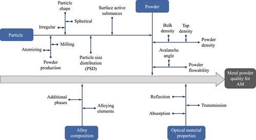
In MAM, powder characteristics play a pivotal role in determining the quality and attributes of the final printed components. Key powder characteristics, including flowability and packing density, are significantly influenced by various powder properties, such as particle shape (e.g. spherical or irregular), size, and their respective distributions. These characteristics and powder properties are interconnected. For instance, in PBF, particle shape and particle size distribution (PSD) influence the powder flowability, which subsequently affects the uniformity of powder bed spreading and its density. Loose powder beds with insufficient packing densities can deteriorate the thermo-mechanical properties of 3D-printed metal components by influencing melt pool behaviour and microstructure formation, potentially resulting in lack-of-fusion porosity.
follows the structure outlined by Spierings et al. [Citation56], utilising an Ishikawa diagram to show these interrelationships between properties and characteristics. It breaks down key parameters that impact the quality of metal powders used in AM. These parameters can significantly impact the printability, mechanical properties, and overall performance of the MAM process. Consequently, powder qualification and characterisation techniques appear as vital considerations in all powder-based AM systems, constituting a dynamic field of ongoing research and development. Common characterisation techniques employed to assess packing density include the Hall flow-meter [Citation57] and tapped density [Citation58] tests. To evaluate flowability, powder flow testers, such as angle of repose (AOR) tests and shear cell testers, are frequently employed (see [Citation59, Citation60]). Recently, Cordova and Chen [Citation61] introduced a virtual characterisation procedure for evaluating flowability in PBF. This procedure utilises a revolution powder analyser based on dynamic AOR and avalanche dynamics.
Figure 6. Ishikawa diagram representing key parameters affecting the metal powder quality in AM.
2.2.3. Heat source and laser-material interaction
One of the most crucial aspects of MAM simulations is modelling the heat source and its interaction with the material, as it defines the thermal boundary condition of the energy balance equation throughout the process. In powder-based applications, the heat source model describes how the beam interacts with the powder particles and the resulting thermal profile.
A significant body of current research in the field of laser-material interactions has been focussed on investigating the relationship between absorbed laser energy and powder morphology. Within this context, computational modelling approaches based on electromagnetic wave theory have demonstrated excellent predictive capabilities. For example, in 2020, Zhang et al. [Citation62] developed a modified electromagnetic wave–heat transfer model, which proved capable of resolving spatial particle distribution and preheating effects resulting from induced current and magnetic heating. A laser-powder interaction model with such capabilities plays a critical role in accurately predicting process outcomes by allowing energy splitting between preheated particles and direct laser heating. Another notable contribution in this field is the development of a novel volumetric heat source model by Yao and Zhang [Citation63]. This model is derived from statistical analysis of particles in spatial distribution and, when applied to a single-track PBF simulation, demonstrates remarkable ability in predicting temperature history and melt pool geometry (see ). For further understanding of the theoretical background and basic mechanisms, additional reading can be found in [Citation64–66].
Figure 7. A close-up of the laser-powder interaction in PBF for two selected particles (A) and the temperature isosurface of the two particles (B), taken from [Citation63].
![Figure 7. A close-up of the laser-powder interaction in PBF for two selected particles (A) and the temperature isosurface of the two particles (B), taken from [Citation63].](/cms/asset/71b9a23e-7c4a-4307-92b2-0f2d3b2cd297/nvpp_a_2274494_f0007_oc.jpg)
Overall, realistic modelling of the heat source remains an active research topic and is very challenging due to several reasons:
Complex physics. The interaction of the laser beam with the metal powder bed involves complex physical phenomena, including absorption, reflection, scattering, and re-emission of radiation. The heat transfer is also affected by factors such as the size and shape of the powder particles, their effective thermal conductivity, and the surrounding environment. Modelling these interactions accurately is a major challenge.
Geometry. The stochastic nature of the powder bed adds another layer of complexity to the heat course modelling from a geometric point of view. It is clear that the local packing of the powder bed strongly influences the laser penetration depth and plays a non-negligible role in the process modelling outcome.
Laser beam characteristics. The characteristics of the laser beam, such as its power, spot size, and shape, can affect the thermal profile of the powder bed. Moreover, the laser beam can vary in intensity over time, leading to non-uniform heating of the powder bed. Accurately modelling these characteristics is critical to the reliability of heat source models and obtaining accurate simulation results.
Scale. The scale of PBF and DED is relatively small, with typical layer thicknesses of around 20-100 micrometers. This makes it difficult to measure and validate the thermal profiles experimentally, highlighting the need for high-resolution modelling and simulation techniques.
Lack of experimental data. There is limited experimental data available for validating the heat source models used in MAM simulations. This makes it challenging to develop accurate models and to quantify the uncertainties associated with these models.
Addressing these challenges requires the development of accurate and validated heat source models that can be used to optimise MAM processes and to guide the design of new materials and structures. Previous studies have recognised these problems and developed different models with varying levels of accuracy and efficiency.
Zohdi [Citation67] classifies such models into four degrees of sophistication, two of which are sufficiently accurate on the powder scale and more common. The first model, referred to as ‘Method 2’ in [Citation67], distributes the incident power into a cylinder assuming a volumetric intensity distribution (e.g. see in [Citation68]). In this way, the laser heat input is typically decomposed into a horizontal intensity distribution, often modelled as a bell-shaped Gaussian density function (e.g. [Citation69–71]), and a vertical absorption distribution. The second model, referred to as ‘Method 3’ in [Citation67], performs a complete ray-tracing scheme by discretizing the heat source into discrete energy portions or ‘rays’ (e.g. see in [Citation72]). shows a graphical sketch of these two models.
Figure 8. Two heat source modelling approaches widely used in simulating MAM processes: volumetric and ray tracing.
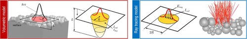
Due to their ease of implementation and lower computational cost, volumetric heat source models are more prevalent than the ray-tracing approaches in AM simulations. Wessels et al. [Citation46] suggest an adaptation of Gusarov's scheme [Citation37], where the intensity distribution in the radial direction is computed from an analytical solution of the radiation transfer equation. For resolving the refraction, the intensity profile in this formulation is a function of the penetration depth (see the shaded volume in ). Another variant of the volumetric heat source approach widely used in MAM simulations follows the Beer-Lambert law to determine the intensity attenuation, as expressed in Equation (Equation10(10)
(10) ). Volumetric models are computationally efficient but can easily degrade the modelling fidelity if absorptivity and extinction coefficients are not identified properly.
Depending on the application, a volumetric model is prone to generate highly inaccurate or completely invalid results. According to experimental and numerical observations in previous studies (e.g. [Citation4, Citation73, Citation74]), most of the laser energy in PBF/DED is reflected, and only a fraction of this heat input is absorbed to a depth of several nanometers. It is, therefore, more realistic to model the laser input as a surface heat source instead of a volumetric one. Different heat source models more sophisticated than a volumetric approach do exist in the literature, two of which are more widespread in AM simulations. (1) The Monte Carlo approach introduced in [Citation75], motivated by a physically-informed foundation in tracing the beam trajectories. (2) The ray-tracing method, as a popular choice among the optics community (cf. [Citation76, Citation77]) to describe the laser-material interaction in detail. According to the conclusions of previous investigations by Yan et al. [Citation75, Citation78, Citation79], it is expected for these two advanced heat source models to have a significant impact on the predicted peak temperatures, thus influencing the recoil pressure, evaporation, and melt pool dynamics.
Ray tracing (RT) is a purely geometrical method as long as there is no diffraction. This is the case in most PBF and DED systems, where the wavelength of the incident radiation is orders of magnitude smaller than the diameter of powder particles. Previous studies have shown that simulation results with a ray-tracing heat source modelling approach are significantly more accurate than those obtained by a volumetric scheme–see [Citation80–86] for further insights. RT models are computationally intensive and, from the algorithmic point of view, hard to couple with numerical discretization methods due to their dependence on resolution consistency and local surface reconstructions.
2.2.4. Melt pool dynamics
The term ‘melt pool’ in AM refers to the localised molten material generated by a heat source that melts and fuses the powdered or wire-form material during the layer-by-layer fabrication process. Intuitively, while it does not function in the same way as a (physical) cutting tool in subtractive manufacturing, the melt pool can be viewed as a non-physical tool that guides MAM processes. illustrates this conceptual definition.
Figure 9. Perceptual analogy between subtractive and additive manufacturing: Similarity of the critical regions (blue frames) and viewing the melt pool as a non-physical tool in AM.
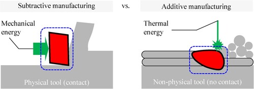
The melt pool region in MAM is the most critical area for modelling as it plays a central role in determining the overall process and can significantly impact the occurrence of manufacturing defects. The melt pool temperature field and its evolution within this region are essential parameters that influence the temperature gradient (G) and solidification rate (R), navigating the microstructure evolution. The local processes in and around the melt pool are highly-dynamic, thermally-driven, multi-phase material transformations that occur on a microsecond time scale. Consequently, a broad range of numerical and material challenges is involved in the computational modelling of the melt pool. Cook and Murphy [Citation27] presented a comprehensive review of the melt pool behaviour, focussing on its mesoscopic simulation aspects. They provide good coverage of melt pool simulations up to 2020 by summarising the simulation capabilities of the (subjectively) leading research groups in this field.
To predict the melt pool geometry and temperature distribution during a metal AM process, the computational modelling framework requires a coupled solution of heat transfer and fluid flow incorporating several physical effects, such as surface tension, wetting, Marangoni convection, evaporation of liquid, recoil pressure, and phase change–see the close-up illustration in . Computational fluid dynamics (CFD) is the most frequently used approach in high-fidelity melt pool simulations that has shown great predictive capabilities in capturing fluid flows involved with these complex dynamics. Even though the application of CFD codes for melt pool simulations in MAM is outside the scope of our review paper, we may digress here to briefly mention a few published works using FVM and FEM approaches.
Gürtler et al. [Citation87] used a finite-volume scheme for simulating the melt pool behaviour in a laser welding application. Although presented in low resolution, the results are seemingly the first 3D simulation of powder melting and re-solidification. Khairallah and Anderson [Citation14] developed and advanced CFD-based modelling framework and simulated a single-track laser PBF process using a hybrid FEM-FVM code, which was massively parallelised. These results demonstrate a fully-resolved particle bed geometry and match with experimental observations to some extent; nevertheless, they rely on a crude surface tension model and neglect the wetting and thermal gradient effects. Focusing on the PBF of Ti6Al4V, Qui et al. [Citation73] applied FVM to investigate the effects of melt pool dynamics on the surface roughness of fabricated parts. King et al. [Citation4] employed the same model as [Citation14] to investigate overhang geometries, where they observed severe balling effects due to high melt pool fragmentation. Although this method does not include a number of crucial physical phenomena (e.g. Marangoni forces, evaporation, and radiation), it gives a good overview of 3D multiscale numerical models for laser PBF problems. Megahed et al. [Citation88] followed an approach similar to [Citation73] and applied a finite-volume formulation of a discrete ordinate radiation model, through which they presented temperature and surface morphology predictions for nickel alloy.
2.2.5. Computational cost
Regardless of the method used, the computational demand for mesoscopic modelling of MAM processes is generally very high because of spatio-temporal resolution requirements and numerical stability issues. Particle methods, in particular, have been recognised to have a relatively higher computational cost compared to their mesh-based counterparts, as argued by many review papers (e.g. see in [Citation89–91]). MAM simulation using particle methods combines the two and faces a prohibitively high cost of computation. Approaches for addressing this challenge include parallel computing (i.e. hardware acceleration) and adaptive discretization (i.e. software acceleration), or the combination thereof.
To achieve high-resolution and high-fidelity simulations of MAM processes with particle methods, it is necessary to minimise the runtime by exploiting both hardware and software capabilities. This is because particle methods require very small discretization sizes and long simulation times, which can become computationally infeasible without parallel computing. This necessity is also evident from the fact that existing works that simulate PBF and DED processes in 3D with reasonable uniform resolutions are all performed on more than one computing core, ranging from multiple to hundreds or even thousands of CPU or GPU cores (see ). Therefore, parallel computing is a crucial requirement for conducting particle-based MAM simulations with high fidelity, as it enables simulations with increased spatial and temporal resolution, and reduces the computational burden of such simulations to a manageable level.
Table 1. Summary of publications from the leading research groups in MAM simulations with hardware-accelerated particle methods.
3. Particle methods for MAM simulations
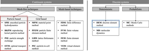
The majority, but not all, of mesh-free techniques are particle-based. provides a categorical overview of numerical methods to avoid this confusion and specify the class of particle-based methods reviewed here. Particle methods are therefore a subset of mesh-free techniques used for simulating various physical systems–from astrophysics and computer graphics to solid and fluid flows. A mesh-free particle method does exactly what it says on the tin: It solves differential equations by a finite set of particles as discretization points without requiring a mesh (i.e. a connection between nodes of the computational domain). The approximation procedure in particle methods is based on the interaction of each particle with its neighbours.
Figure 10. A general classification of numerical techniques, highlighting the category of particle-based methods.
In principle, a particle method is an interpolation technique developed from a simple idea: Consider particles as material interpolation points and follow them in their motion. These particles discretise a continuum in space and carry its extensive and intensive quantities in a Lagrangian frame. Since there is no computational mesh in such methods, particle-based interpolation is merely based on the particle position and the use of a weighting function. It can be realised from this description that particle methods are mesh-free and inherently mass-conservative. As a result, the physical entities are carried by a set of moving interpolation points being advected by the motion, conserving the mass over time. This numerical approximation procedure reveals several advantages of particle-based methods over mesh- and grid-based techniques:
Conservation of mass is simple (and usually guaranteed).
Handling large deformations is easy with no theoretical limit.
Great ability to follow free-surface flows and material/phase interfaces.
Ideal for parallel computing due to local and pairwise interactions.
These attractive features match the modelling requirements discussed in Section 2.2, making particle methods a prime candidate for efficient MAM simulations. Two particle-based methods currently used for such applications on the powder scale are SPH (smoothed particle hydrodynamics) and OTM (optimal transport meshfree). Other mesh-free techniques such as the material point method (MPM) and lattice Boltzmann method (LBM) have also been used for power-scale MAM simulations. Examples include a 2D LBM approach of Körner et al. [Citation98] for modelling PBF and a basic MPM numerical framework developed by Maeshima et al. [Citation99] for an AM sintering application. Nevertheless, we leave these approaches out of the present review as they do not fall into the category of ‘particle-based’ methods specified in .
In what follows, we first revisit the basic theory of DEM as the most prominent method for modelling powder behaviour in MAM. Then, a brief description of SPH and OTM, including the basic steps for computer implementation, is given without delving into their derivation details.
3.1. Discrete element method (DEM)
Introduced by Cundall and Strack [Citation100] in the late 70 s, DEM is a numerical technique for modelling the behaviour of systems of discrete bodies (i.e. granular assemblies) that interact with each other. This method is well-suited for studying the intricate properties and behaviour of powder particles in AM.
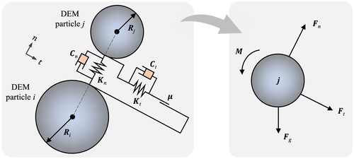
The equation of motion of each powder particle in DEM is Newton's second law, including both transnational and rotational terms: (14)
(14)
(15)
(15) where
is the acceleration, m the mass,
the total contact force comprising of the normal and tangential components (see ), g the gravity, ω the rotational velocity,
the total contact torque, and I the moment of inertia. These two accelerations are numerically integrated over a time step to update the velocity and position of each DEM particle. The primary task in DEM powder modelling is to detect particle collisions and compute the contact forces. The contact force computation is typically performed through a soft-sphere approach, where deformations during contact are represented by an artificial overlap between two rigid DEM particles. shows a 2D schematic representation of this contact model, in which
and
are the spring stiffness and dashpot damping in the contact normal direction, respectively. The tangential spring stiffness
together with the friction coefficient μ represent friction between particles i and j.
Figure 11. Illustration of the contact interactions between two DEM particles and the diagram of resultant forces acting on particle j.
3.2. Smoothed particle hydrodynamics (SPH)
Introduced independently by Monaghan and Gingold [Citation101] and Lucy [Citation102] in 1977, SPH is a Lagrangian mesh-free method originally used for solving astrophysical problems in three-dimensional open space. While not being the first particle method in general, SPH is definitely the most popular and well-studied meshfree scheme to date–often regarded as the oldest modern meshfree particle method.
The interpolation procedure in SPH solutions begins with a property of the Dirac delta function δ and is carried out through a smoothed weighted averaging, followed by a numerical quadrature. Therefore, two kinds of approximation errors are encountered in the derivation of SPH: the kernel approximation error, and the particle approximation error. Expressed mathematically:
| (1) | Kernel approximation: | ||||
| (2) | Particle approximation: | ||||
where is an arbitrary function at location x in a bounded domain Ω,
the weight of integration, and
the SPH kernel function. The smoothing length h in
is defined as the parameter that determines the size of a finite smoothing domain, i.e. the support domain, which contains a set of N neighbouring particles. shows the support domain of particle i at the initial (
) and current (
) configurations, as well as the nearest neighbours of i highlighted in green. Since the smoothing kernel W is the only term that is spatially sensitive, SPH discretizations for derivatives can be obtained by just transferring the differential from f onto the smoothing function W. A verbose analytical proof of this procedure for deriving differential operators can be found in SPH textbooks [Citation103] and review papers [Citation89, Citation104].
Figure 12. Illustration of the SPH approximation scheme in 2D. Spatial discretization by material points or particles (red circles) is shown at the initial () and current (
) configurations. Support domain of material point or particle i and its affected neighbours (i.e. green circles) are updated at each time step.
Algorithmic 1 Main implementation tasks for a computation step in SPH
Require: Initial set of particles (or material points P)
Require: Updated boundary conditions
Ensure: There is no physically invalid particle in the system
| 1: | Re-construct the list of nearest neighbours | ||||
| 2: | Compute kernel approximations | ||||
| 3: | Solve governing equations (i.e. constitutive update) | ||||
| 4: | Update the position of particles (or material points P) | ||||
The SPH formalism can be described in either a ‘total’ or ‘updated’ Lagrangian frame. An updated Lagrangian SPH (i.e. ULSPH) framework describes the continuum in its current configuration, whereas the total Lagrangian SPH (i.e. TLSPH) formulation represents the continuum at the initial state. Searching literature shows no result in modelling AM processes with a TLSPH scheme. Consequently, the abbreviation SPH throughout this manuscript refers to the updated Lagrangian SPH formalism unless otherwise stated. The key tasks for implementing a computation step in SPH are outlined in Algorithm 1.
3.3. Optimal transportation meshfree (OTM)
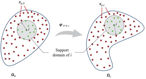
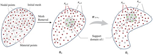
Introduced by Li et al. [Citation105] in 2010, OTM is a particle-based method formulated in the updated Lagrangian framework for simulating solid and fluid flows. The OTM methodology can be realised as a combination of the optimal transport theory with material point sampling and meshfree interpolation kernels. As shown in , the computational domain in OTM is discretised by two sets of points: (1) Nodal points; (2) Material points. The nodal points ( white squares in ) carry the kinematic information of the body, such as displacement, velocity, and acceleration. At these nodes, primary variables are computed by solving the discretised equations of motion. The material points (
red circles in ) are used as integration points, where quantities like strain, stress, internal variables, and material properties are evaluated. In OTM, the material point sampling facilitates efficient numerical integration without a background mesh. The method requires a search algorithm to establish the connectivity between the nodal and material points for interpolation purposes. This algorithm dynamically reconstructs the nodal-material points connection on-the-fly based on the local deformation at each time step. The key tasks for implementing a computation step in OTM are outlined in Algorithm 2.
Algorithmic 2 Main implementation tasks for a computation step in OTM
Require: Initial sets of nodal point A and material points P
Require: Updated boundary conditions
Ensure: There is no physically invalid material point in the system
| 1: | Compute local mass matrix and local force vector at nodal points | ||||
| 2: | Update kinematic variables and the position of nodal points | ||||
| 3: | Update the position of material points | ||||
| 4: | Solve governing equations (i.e. constitutive update) at material points | ||||
| 5: | Apply search algorithm and construct the list of nearest neighbours (support domain update) | ||||
| 6: | Re-compute shape functions | ||||
Figure 13. Initial triangulation of the domain and illustration of the OTM approximation scheme in 2D. Spatial discretization by nodal points (white squares) and material points (red circles) is shown at the initial () and current (
) configurations. Support domain of material point i and its affected nodes (i.e. green squares) are updated at each time step.
Due to its incremental updated Lagrangian formulation, the original OTM method is prone to numerical instabilities and inconsistency issues–just like SPH. Current approaches to mitigate these shortcomings are the stabilised OTM scheme developed by Weissenfels and Wriggers [Citation106] and the hot OTM (HOTM) method proposed by Wang et al. [Citation107]. For simplicity, we use the OTM acronym as a unified indication of these different schemes in MAM simulations.
3.4. DEM capabilities in MAM simulation
DEM is primarily employed for modelling powder behaviour and deposition in various applications. However, this versatile tool can also be utilised for heat transfer analyses. The following subsections categorise the respective developments in the MAM domain.
3.4.1. Powder modelling
The applications of DEM for the numerical analysis of powder behaviour in AM are numerous. One significant group of these applications focuses on the use of DEM for investigating powder metallurgy and for qualification purposes without simulating the laser-material interaction. Another group couples DEM powder modelling with fluid flow simulations to study the effects of powder particles on melt pool geometry and process outcomes. We summarise some notable works categorised into these two groups:
Purely DEM frameworks Chen et al. [Citation108] employed DEM to analyse the effect of packing density on the quality of fabricated parts. Han et al. [Citation109] investigated the influence of powder layer thickness on various powder-bed characteristics and validated their results through experiments. Meier et al. [Citation110] conducted a detailed study of the impact of particle characteristics on powder layer uniformity (see ). Further studies on various other aspects of AM powder flowability, spreading dynamics, and size/shape distribution effects can be found in [Citation111–114].
provides a summary of key information from published works investigating powder spreadability in MAM using DEM. Notably, it reveals a gap in the literature concerning DEM-based powder spreadability analyses in DED processes. For a more in-depth discussion, readers are referred to a 2021 review paper by Sehhat and Mahdianikhotbesara [Citation115], which primarily focuses on powder spreading aspects in PBF processes.
DEM has also been utilised to evaluate powder flowability indirectly through proxy powder characterisation techniques. Bouabbou and Vaudreuil [Citation121] devised a virtual Hall flow-meter characterisation technique for PBF and validated their model using static AOR and mass flow rate measurements. Another noteworthy application of DEM is its use in investigating powder flow tests with the well-known Freeman FT4 powder rheometers. This approach has demonstrated satisfactory results in various application fields, including pharmaceutical [Citation122] and chemical engineering [Citation123], although it has not yet been developed for use in AM processes.
DEM coupled with a continuum-based numerical technique Coupling DEM with continuum-based numerical methods such as FEM and SPH is an established and effective way to tackle fluid flow and hydrodynamic problems in particulate media. In the MAM domain, Steuben et al. [Citation124] demonstrated the applicability of DEM for capturing the varying distributions of heat and mechanical forces within the laser sintering process. A particularly notable work in this field is the integrated DEM-CFD modelling framework of Yan et al. [Citation125], which was developed to simulate multiple powder spreading-melting sequences. See . Within a meshfree process simulation framework, Fan et al. [Citation93] provided a systematic approach for modelling the powder spreading process during PBF that adopts an adjustable powder packing procedure with experimental thresholds. They coupled their DEM powder model with an OTM-based melt pool simulation.
Broader coverage of recent DEM developments within and beyond the AM simulation domain can be accessed in Chen et al. [Citation126, Citation127], respectively.
Figure 14. Screenshots of a powder recoating model using DEM (left) and particle size distribution with its colour code definition (right), reprinted from Meier et al. [Citation110] with permission from Elsevier.
![Figure 14. Screenshots of a powder recoating model using DEM (left) and particle size distribution with its colour code definition (right), reprinted from Meier et al. [Citation110] with permission from Elsevier.](/cms/asset/569fb749-6b22-41c7-a56b-a17198e6590a/nvpp_a_2274494_f0014_oc.jpg)
Figure 15. Coupled DEM-CFD modelling framework of powder packing and melt pool simulation in a multi-layer electron beam melting process by Yan et al. [Citation125], reprinted with permission from Elsevier.
![Figure 15. Coupled DEM-CFD modelling framework of powder packing and melt pool simulation in a multi-layer electron beam melting process by Yan et al. [Citation125], reprinted with permission from Elsevier.](/cms/asset/92db4a9b-5183-4b2d-8930-1b18a0f71fac/nvpp_a_2274494_f0015_oc.jpg)
Table 2. Summary of notable DEM-based powder spreadability analyses in MAM (since 2018).
3.4.2. Thermal modelling
DEM models that are capable of capturing heat transfer mechanisms are also referred to as thermal DEM-based models in the literature. These models, which have seen continuous development over decades and wide industrial applications (see in [Citation128, Citation129]), can offer significant advancements for MAM process simulations. This potential improvement is due to the following reasons:
They allow for solving the heat transfer equation within the powder system without the need to discretise each powder particle using continuum-based numerical methods like SPH or OTM. This results in substantial runtime acceleration and memory savings.
They efficiently capture the thermal interactions between the heat source and powder particles before reaching the substrate, which is particularly important in DED, where partial melting of powder particles is a critical consideration.
For more details, interested readers are referred to a comprehensive review by Peng et al. [Citation130] that provides an in-depth discussion of thermal DEM-based models from theoretical and application perspectives.
3.5. Current SPH and OTM approaches for modelling PBF
High-fidelity simulation of MAM processes using particle methods began 5-6 years ago and has been a continuing activity ever since. The application of these methods, namely SPH and OTM, to 2D and simplistic MAM geometries is limited to a small number of SPH developments. In 2018, Russell et al. [Citation42] pioneered the use of SPH in 2D single-track PBF simulations considering all dominant material-thermal-mechanical effects, marking the beginning of ongoing research in this area. (A) shows the velocity field for the melt pool region, as well as two snapshots of the material state and temperature contours for the laser melting of a 2D particle bed. During a similar time-frame, Liu et al. [Citation131] devised another 2D mathematical model of PBF utilising the SPH method to simulate the deformation patterns of the longitudinal morphology of a molten pool during laser melting, taking into account the impact of surface tension ((B). Their modelling framework was comparatively less advanced than that of Russell et al. [Citation42], and in general, 2D models of PBF lack reliable experimental validation, making them susceptible to producing precise predictions.
Figure 16. 2D mesoscopic SPH simulations of PBF. (A) Russell et al. [Citation42] using a robust weakly-compressible SPH for simulating a PBF process at the powder scale, spending ≈ 36 hours for simulating a 1-mm long track; (B) The distributions of the velocity field temperature in a single-layer PBF track performed by Liu et al. [Citation131]; (C) The first multi-resolution SPH simulation of a PBF process, running 2x faster than a single-resolution model, developed by Afrasiabi et al. [Citation132]. The state scale is linear, starting from the liquid state represented by red, down to the solid state shown in blue.; (D) Multi-layer PBF simulation enabled by integrating a rainfall-like rigid powder model into the SPH thermal-fluid solver, presented in [Citation133].
![Figure 16. 2D mesoscopic SPH simulations of PBF. (A) Russell et al. [Citation42] using a robust weakly-compressible SPH for simulating a PBF process at the powder scale, spending ≈ 36 hours for simulating a 1-mm long track; (B) The distributions of the velocity field temperature in a single-layer PBF track performed by Liu et al. [Citation131]; (C) The first multi-resolution SPH simulation of a PBF process, running 2x faster than a single-resolution model, developed by Afrasiabi et al. [Citation132]. The state scale is linear, starting from the liquid state represented by red, down to the solid state shown in blue.; (D) Multi-layer PBF simulation enabled by integrating a rainfall-like rigid powder model into the SPH thermal-fluid solver, presented in [Citation133].](/cms/asset/1ff81002-7c6f-49da-8ca6-747f90cf0327/nvpp_a_2274494_f0016_oc.jpg)
In addition to the advancements mentioned above, there have been two notable developments that extend the 2D high-fidelity SPH model for larger MAM simulations. The first development, presented by Afrasiabi et al. [Citation132], proposed a multi-resolution approach that incorporates dynamic zone refinement ((C)). This resulted in a significant reduction in computational time, saving up to 50%. The second development, presented in [Citation133], is the integration of a rigid powder model into the SPH thermal-fluid solver that enabled the simulation of multi-layer PBF processes through capturing the layer-by-layer build-up procedure. (D) taken from [Citation133] is a simulation frame at the 10th layer, where the scanning laser and temperature distribution are shown. This advancement allows for a more comprehensive simulation of the AM process by considering the interaction between the solid powder particles and the liquid or solidified track. Subsequently, these extensions marked the culmination of 2D works in the field, as researchers have shifted their focus towards the development of 3D models, driven by concerns regarding accuracy and reliability.
While earlier publications lacked the necessary resolution and/or modelling accuracy, they established the initial understanding of the particle-based methods' effectiveness in AM simulations. These studies also derived the basic mathematical framework governing the mesoscopic multi-physics analyses. For instance, see the DEM-SPH thermomechanical modelling framework of Park and Zohdi [Citation137] used for droplet-based AM processes. Another notable example of the potential of particle-based thermomechanical simulations in AM is the work by Hu and Eberhard [Citation85]. They conducted numerical simulations of a laser spot welding process involving aluminum and demonstrated promising results, suggesting that SPH has significant potential for large-scale manufacturing simulations. Additionally, Trautmann et al. [Citation138] developed a 3D SPH modelling framework for a material processing application, specifically Tungsten Inert Gas (TIG) welding. Although it falls outside the realm of AM, their work is worth mentioning due to some fundamental similarities in problem formulation. They validated their numerically computed results by comparing them to experimentally measured penetration profiles at different weld currents. These early advancements in particle-based simulations have paved the way for further exploration and refinement of MAM processes.
As mentioned, a 2D model of PBF and DED processes would be theoretically questionable and inaccurate for several reasons. These processes involve the deposition of material and heat transfer, which occur in a three-dimensional environment. Additionally, the powder particles exhibit stochastic orientations, and the laser (or electron) beam can interact with the material from various off-plane angles. Due to these factors, the 2D assumption is unrealistic for real experimental validation, leading researchers to focus primarily on developing 3D models. Weirather et al. [Citation36] presented a rigorous SPH model for laser beam melting simulation of Inconel 718 ((B)). Using GPU parallel computing, they employed 11 million SPH particles, achieving a fine spatial resolution of 1 μm. In a similar vein, Fürstenau et al. [Citation92] developed a GPU-accelerated 3D SPH model for laser PBF, which also demonstrated high-resolution SPH simulations with a particle size of 1 μm, the finest achieved to date ((A). Dao and Lou [Citation94] applied SPH to simulate both PBF and DED processes, validating their work with experimental data from other references (see (F)). They claimed their SPH model to be the most comprehensive and complete for laser fusion AM simulations. Although their model used 13 million SPH particles and ran on 240 CPU cores in parallel, the finest resolution in their study was 2-3x coarser than what Fürstenau et al. [Citation92] achieved through GPU acceleration.
Figure 17. 3D SPH simulations of PBF: (A) Fürstenau et al. [Citation92]; (B) Weirather et al. [Citation36]; (C) Liu et al. [Citation134]; (D) Qiu et al. [Citation135]; (E) Meier et al. [Citation96, Citation136]; (F) Dao and Lou [Citation94]. Images are adapted from the original publications with permission.
![Figure 17. 3D SPH simulations of PBF: (A) Fürstenau et al. [Citation92]; (B) Weirather et al. [Citation36]; (C) Liu et al. [Citation134]; (D) Qiu et al. [Citation135]; (E) Meier et al. [Citation96, Citation136]; (F) Dao and Lou [Citation94]. Images are adapted from the original publications with permission.](/cms/asset/e3c5c9f1-bbb4-428d-b88b-98425164f295/nvpp_a_2274494_f0017_oc.jpg)
The most complete and efficient SPH scheme for MAM simulations is still under exploration, but two research groups have made important headway in this area. Meier and Fuchs et al. [Citation96, Citation97, Citation136] have developed a versatile in-house code capable of modelling various MAM processes, including PBF. Their code incorporates a detailed physical formulation and achieves high numerical resolution due to massive parallelisation. Additionally, they utilise a powerful DEM tool to accurately model large-scale power deposition and recoating processes ((E)). The second group has recently published works, led by Afrasiabi and Lüthi et al. [Citation139, Citation140], that focus on the computational performance of particle-based MAM simulators. They specifically address software acceleration in their in-house SPH code, ‘iMFREE’, through adaptivity. This approach significantly reduces runtime by up to 80%, enabling multi-track PBF simulations without the need for extensive parallelisation. See for more a detailed demonstration. Although additional 3D MAM simulations using SPH exist (e.g. the works of Liu et al. [Citation134, Citation135] shown in (C–D), they are not as advanced or comprehensive as the references discussed above in terms of geometry, modelling fidelity, and resolution.
Figure 18. 3D high-fidelity simulation with single- and multi-resolution SPH. (A) High-fidelity PBF simulation with a single-resolution SPH scheme to quantify the effects of recoil pressure and Marangoni forces on the melt pool geometry, taken from Afrasiabi et al. [Citation139]; (B) Four solidified parallel tracks and surface height values in a multi-track PBF process simulated by the multi-resolution SPH code of Lüthi et al. [Citation140]. The discretization size varies from 61.8 (coarsest) to 3.8 (finest) μm.
![Figure 18. 3D high-fidelity simulation with single- and multi-resolution SPH. (A) High-fidelity PBF simulation with a single-resolution SPH scheme to quantify the effects of recoil pressure and Marangoni forces on the melt pool geometry, taken from Afrasiabi et al. [Citation139]; (B) Four solidified parallel tracks and surface height values in a multi-track PBF process simulated by the multi-resolution SPH code of Lüthi et al. [Citation140]. The discretization size varies from 61.8 (coarsest) to 3.8 (finest) μm.](/cms/asset/a981d52d-4317-4959-b700-04700e09e08e/nvpp_a_2274494_f0018_oc.jpg)
Compared to SPH, the availability of developments for modelling PBF using OTM is relatively limited. provides a summary of the most notable publications in this context, with the single-track simulation results of Fan et al. [Citation93] shown in (B) being the most comprehensive among them. The authors employed DEM to create realistic a powder bed with essential statistical information and coupled it with a stabilised OTM method for describing the thermo-visco-elastic response of the metallic particles in PBF. In 2019, Fan and Li [Citation141] presented a less advanced development with simpler modelling features based on OTM, simulating laser melting of a solid substrate without powder ((A). Although tested on a simplistic laser melting of only two metal powder particles ((C), which can hardly be considered a full PBF process, the stabilised OTM scheme of Wessles et al. [Citation46] in 2018 is considered the origin of OTM developments for PBF simulations. Their subsequent study [Citation142] focussed on the heat source modelling aspect of fusion-based AM simulations using OTM, introducing an efficient ray tracing algorithm to resolve detailed laser-material interactions, which works effectively with an OTM-like meshfree discretization ((D)).
Figure 19. Overview of fusion-based MAM simulation using OTM schemes. (A) A 7 mm PBF track simulated by Fan and Li [Citation141] using adaptive (mesh) discretization size ranging from 25–1000 μm in an HOTM setup; (B) Fan et al. [Citation93] using the same method but at a much higher resolution using about 1.3 million material points for a 1.6 mm track; (C) Work of Wessels et al. [Citation46] on modelling the fusion of two metal particles fusion with a stabilised OTM code; (D) A similar metal particle fusion example simulated by Wessels et al. [Citation142] with an enhanced ray-tracing heat source model.
![Figure 19. Overview of fusion-based MAM simulation using OTM schemes. (A) A 7 mm PBF track simulated by Fan and Li [Citation141] using adaptive (mesh) discretization size ranging from 25–1000 μm in an HOTM setup; (B) Fan et al. [Citation93] using the same method but at a much higher resolution using about 1.3 million material points for a 1.6 mm track; (C) Work of Wessels et al. [Citation46] on modelling the fusion of two metal particles fusion with a stabilised OTM code; (D) A similar metal particle fusion example simulated by Wessels et al. [Citation142] with an enhanced ray-tracing heat source model.](/cms/asset/48a9c0be-4ee7-48dc-97fb-7294172edf68/nvpp_a_2274494_f0019_oc.jpg)
Apart from the SPH and OTM approaches, there is another numerical technique used for melt pool simulation which can still be considered mesh-free according to the classification in : The lattice Boltzmann method (LBM) [Citation143]. This kinetic approach is particularly well-suited for handling complex inter-phase boundaries and can run efficiently on massively parallel architectures. Körner et al. [Citation70] developed the first 2D fine-scale model of the LPBF process on the powder scale using an LBM approach, where they predicted the melting behaviour as a function of some process parameters like the scan speed and powder properties. The model, however, misses some crucial physical effects, such as the Marangoni forces and recoil pressure. Ammer and her co-workers [Citation144] adopted a statistical powder bed generation algorithm and developed a 3D model of selective electron beam melting on Ti6Al4V. The simulation results of electron beam melting in this work are presented without validation, however. Overall, commercial software using LBM is still immature, and the implementation of some important physics such as temperature-dependent surface tension and complex boundary conditions is not straightforward.
3.6. Current SPH and OTM approaches for modelling DED
Numerical modelling and simulation of DED is inherently more challenging compared to PBF, irrespective of the method used, including particle-based approaches. In DED, material is deposited directly onto the substrate or previously deposited layers as the printing head moves along a predefined path. The material is melted by a focussed energy source (such as a laser or electron beam) as it is being deposited. The deposition happens continuously and ‘on the fly’, meaning the material is added in real time during the printing process. This dynamic and continuous deposition process introduces an additional level of complexity to modelling DED in terms of material delivery rates, energy input, heat transfer effects, and resolving the solid-liquid interactions.
While continuum-based particle methods like SPH and OTM have demonstrated their efficacy in capturing fluid behaviour in MAM, a complete representation of the entire DED process requires their coupling with a discrete modelling approach for real-time powder deposition. This coupling of continuum-based particle methods (SPH/OTM) with a discrete model (most commonly DEM) adds yet another layer of complexity to the simulation, rendering the overall modelling process highly demanding. The seamless interaction between the fluid and solid phases in DED processes necessitates accurate and efficient communication between the continuum and discrete models. However, this coupling can introduce numerical instabilities and challenges in preserving mass, momentum, and energy conservation across the fluid-solid interface. Achieving the necessary computational efficiency and stability in such coupled models remains an ongoing research area, contributing to the limited application of particle methods in DED simulations.
Very few existing published works on particle-based DED simulation have emerged within the last three years. In 2020, Wang et al. [Citation107] presented the first high-fidelity DED simulation with a particle method using OTM ((C)). They modelled 200 metallic particles and simulated about 3 ms of the process without coupling solid-liquid interactions, facing thermodynamic inconsistencies during phase transition and inaccuracies in calculating surface properties such as the Marangoni effect. Dao and Lou [Citation94] developed a more comprehensive and fully SPH-based computational framework for simulating DED, which accounted for solid-liquid interactions without using DEM for solid particle representation ((A)). In their follow-up study [Citation95], the authors utilised the same methodology but extended the size of their DED simulation through massive parallelisation, leading to higher-resolution results ((B)).
Figure 20. State of the art in particle-based simulation of DED. (A) Dao and Lou [Citation94] using approximately 1.2 million SPH particles in their initial attempt and spending about 7h on 24 supercomputer CPU cores for 0.5 ms of a DMD process; (B) Dao and Lou [Citation95] using 1.6 million SPH particles and spending about 230 h on 24-core parallel CPU nodes to simulate 0.5 s of the DED process in their more recent work; (C) work of Wang et al. [Citation107] using an in-house serial OTM code to simulate a single-track DED with depositing 200 metallic particles.
![Figure 20. State of the art in particle-based simulation of DED. (A) Dao and Lou [Citation94] using approximately 1.2 million SPH particles in their initial attempt and spending about 7h on 24 supercomputer CPU cores for 0.5 ms of a DMD process; (B) Dao and Lou [Citation95] using 1.6 million SPH particles and spending about 230 h on 24-core parallel CPU nodes to simulate 0.5 s of the DED process in their more recent work; (C) work of Wang et al. [Citation107] using an in-house serial OTM code to simulate a single-track DED with depositing 200 metallic particles.](/cms/asset/dc0bb9f1-6261-4c53-877f-243880074ead/nvpp_a_2274494_f0020_oc.jpg)
3.7. Current meshfree simulation approaches for modelling BJ
Unlike PBF and DED, which involve complex coupling of thermo-hydrodynamic and material phase change effects, BJ is primarily concerned with binder flow and powder dynamics. Consequently, achieving high-fidelity modelling of the BJ process is relatively less complicated. Surprisingly, however, there is a notable scarcity of research in this domain, particularly on the application of meshfree particle-based simulation frameworks. To the best of our knowledge, the only available high-fidelity simulation of BJ employing particle methods was published by Fuchs et al. [Citation97] a year ago. illustrates sectional and complete views of two BJ simulation results from this study, where they modelled the coupled microfluid-powder dynamics using a CPU-accelerated SPH code.
Figure 21. State of the art in multiphysics high-fidelity modelling of BJ with meshfree particle-based [Citation97] and mesh-based CFD [Citation147] simulation approaches.
![Figure 21. State of the art in multiphysics high-fidelity modelling of BJ with meshfree particle-based [Citation97] and mesh-based CFD [Citation147] simulation approaches.](/cms/asset/f5dd2d4d-73c4-4ea1-929c-42591c1a6e19/nvpp_a_2274494_f0021_oc.jpg)
Most other BJ simulation studies rely on CFD codes, with a primary focus on the saturation equilibrium [Citation145] and droplet penetration [Citation146] issues of liquid binder droplets without coupling the effects of microfluid and powder dynamics. An exception to this is the very recent publication by Yang et al. [Citation147], which came out only during the revision process of this review paper. The computational process model in [Citation147] was used to reproduce the impingement of binder droplets, binder penetration, and the movement of powder particles. The right image in displays a few selected screenshots from this research.
summarises this review by presenting a non-exhaustive collection of papers that have utilised particle methods for MAM simulations, as discussed in Sections 3.5–3.7. The papers are categorised based on their focus of application: PBF, DED, and BJ.
Table 3. Overview of notable particle-based MAM simulations published in the past five years.
3.8. Capabilities and limitations in modelling MAM processes
While the discussion and literature research in the preceding sections primarily centred around SPH and OTM methods, the strengths of particle methods can be conclusively addressed as a collective group, taking into account their combined contributions and demonstrated abilities in achieving detailed simulations of MAM processes. Their main capabilities in such applications include:
Straightforward multi-physics coupling. Particle methods facilitate the coupling of multiple physical phenomena involved in MAM processes like PBF and DED. They can handle simultaneous interactions between fluid flow, heat transfer, mechanical deformations, and material phase changes due to their Lagrangian, point-wise formulations.
Strength in handling complex geometries. Particle methods excel at handling complex geometries, as they do not require a fixed computational mesh. This flexibility allows them to simulate intricate shapes encountered in MAM processes without the need for mesh (re-)generation, simplifying the modelling process.
Ideal for capturing material flow and large deformations. Particle methods are well-suited for problems involving large deformations and material flow phenomena like PBF/DED processes as representing the material with moving particles enables them to accurately track the material behaviour and flow dynamics during the process.
Facilitating adaptive refinement. Particle methods offer an optimal solution for adaptive refinement by enabling adjustments in particle distribution or size based on local criteria. This capability proves particularly advantageous in tackling multi-scale problems such as PBF/DED, where a wide range of phenomena occurs across different length scales (i.e. satisfying different spatial resolution requirements).
Suitability for massive runtime accelerations through parallel computing. Particle methods are well-suited for leveraging the power of parallel computing architectures. The inherent parallelism in particle-based simulations allows for efficient utilisation of modern computing resources, such as multi-core CPUs or GPUs, enabling significant runtime acceleration. This parallel computing capability makes particle methods particularly suitable for addressing the computational demands of fine-scale MAM simulations.
Particle methods are not without their limitations and shortcomings in MAM simulations. Some of the key issues concluded from the reviewed publications are as follows:
Numerical dissipation, stability, and convergence issues. Meshfree methods face numerical dissipation, stability, and convergence challenges. These issues can lead to the damping of high-frequency oscillations and inaccuracies in capturing small-scale details, common in MAM processes. Achieving stability and convergence often involves adjusting parameters, such as smoothing length and time step, through an iterative process. Implementing stabilisers and corrective terms can be complex and not easily transferable between applications.
Challenges in surface representation and boundary treatment. Particle methods cannot explicitly represent surfaces, posing challenges in processes like PBF/DED, where laser/electron beam interactions with material surfaces are critical. Without explicit surface representation, accurately resolving these interactions is difficult. Handling surface effects in particle-based MAM models requires extra treatment and is less straightforward than in grid-based models.
Complexity in implementing advanced heat source models. The (over)simplicity of heat source modelling approaches in current particle-based MAM simulations can be largely attributed to the lack of an explicit surface representation inherent in meshfree methods. Standard mesh-based models of MAM processes are devoid of this issue. High-fidelity heat source modelling techniques, such as ray tracing, heavily rely on surface information, making them less straightforward to implement in particle-based simulations. Particle methods require cumbersome and time-consuming procedures to reconstruct an explicit material surface (e.g. by surface triangulation), which serves as a prerequisite for incorporating high-precision heat source models.
High computational cost. Particle methods typically incur higher computational costs compared to mesh-based methods due to a relatively larger number of interacting neighbours and shorter time step sizes. The calculations involved in MAM process modelling using particle methods require significant computational resources, resulting in long simulation times. Without runtime acceleration techniques, simulating even a few millimeters of the PBF/DED process at high resolution becomes impractical, often taking several days or weeks to complete.
Unavailability of dedicated software tools. Commercial or non-proprietary software specifically tailored for particle-based MAM simulations is currently lacking in the market. Although powerful multiphysics and CFD simulation packages like Flow3D-AM [Citation149, Citation150] exist, these tools predominantly rely on mesh discretization methods, which may not offer native support or optimised capabilities for efficiently handling particle-based simulations in the context of metal AM processes. Additionally, the use of in-house codes for particle-based simulations necessitates additional efforts for verification and validation, including benchmark testing and comparison with experimental measurements, to ensure their reliability and accuracy in real-world metal AM scenarios.
Visualization and post-processing issues. The nature of the data output in particle simulations is typically in the form of ‘points’ containing columns of particle positions, velocities, forces, and other relevant properties. Unlike grid-based methods, MAM simulation results using particle methods are represented as a point cloud, which lacks depth information in three dimensions, making it difficult to interpret without additional post-processing steps. Moreover, generating basic visualisation forms for modelling analysis, such as contour plots, streamlines, or slices, based on point cloud data is not feasible due to the lack of connectivity between particles.
A summary of particle methods' strengths and limitations in MAM simulation compared to the mesh-based approaches is presented in .
Figure 22. Comparative analysis of particle-based and mesh-based methods for multi-physics MAM process simulation at the powder scale, highlighting their respective capabilities and limitations. The utilisation of emojis serves to visually elucidate that the management of ‘Aspect X’ in MAM simulations is inherently more intuitive and efficient when employing particle-based or mesh-based techniques.
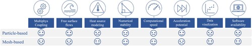
4. Discussion
The exploration of published works in Sections 3.5–3.6 revealed the evolution and successful application of SPH and OTM in simulating MAM processes (refer to ). In this section, our focus shifts to a critical analysis of the methodological and phenomenological limitations inherent in current MAM process modelling with particle methods, with a particular emphasis on their relevance to addressing multi-physics and multi-scale problems. By discussing these points, we aim to highlight the complementary benefits that arise from coupling different methods in MAM simulations -- see . Furthermore, we categorise the core technical characteristics of SPH and OTM within the context of MAM process modelling and provide further insights from most recent results obtained by other competitive and established approaches. This classification enables us to outline clear and targeted pathways for future research, emphasising the potential advancements in developing particle-based simulation techniques for metal additive manufacturing.
4.1. Summary of current particle-based MAM simulations
As indicated, SPH is currently the dominant choice for modelling MAM processes with a particle method and without mesh. The relatively limited availability of OTM developments and other mesh-free techniques such as MPM [Citation99, Citation151] or PFEM [Citation152, Citation153] in this context can be attributed to SPH's overwhelming development, algorithmic maturity, and more established track record across various fields of application.
The prevalence of SPH over OTM in modelling MAM processes is also linked to a process-specific technical aspect, which directly affects the accuracy of melt pool simulations. The SPH method satisfies the requirements for conserving balance equations with no (or negligible) violation of the integration constraint. Moreover, it effectively avoids the well-known ‘tensile instability’ issue often encountered in solid mechanics applications, which is of limited concern in MAM processes. However, the SPH shape (or kernel) functions do not fully meet the reproducing conditions unless corrective schemes such as CSPM [Citation154, Citation155], or higher-order kernels like [Citation104, Citation156, Citation157] are adopted. Unlike SPH, the OTM method excels in fulfilling reproducing conditions and preserving momentum and angular momentum. However, it violates the integration constraint, which is crucial for normal vectors, curvature, and surface force calculations. Additional correction schemes (e.g. [Citation106]) are necessary to address these issues and ensure convergent surface force approximations.
To conclude, the key issues and knowledge gaps we have identified in the preceding discussions are summarised below as potential development areas for future particle-based MAM simulations:
| (1) | Incorporation of realistic powder morphology and recoating process into the laser melting model. | ||||
| (2) | Validated and more accurate heat source modelling beyond traditional volumetric approaches that can resolve multiple reflection-absorption scenarios. This is one of the most crucial elements for precise predictions of keyhole formation. | ||||
| (3) | Identification of (at least crucial) material data, such as absorption and heat capacity coefficients, instead of borrowing them from other, and not necessarily consistent, references. | ||||
| (4) | Accounting for the gas and evaporation models, which play a pivotal role in different defect formation mechanisms and are lacking from existing frameworks. | ||||
| (5) | Design and conduction of preliminary validation experiments with less uncertainties before evaluating the solver's performance in a full process simulation. | ||||
| (6) | Combination of parallel computing and adaptive resolution for optimal runtime acceleration. | ||||
| (7) | Effective coupling of particle methods with other discrete (e.g. DEM) and continuum (e.g. FEM or FVM) approaches to facilitate multiscale modelling of real-world AM scenarios. | ||||
4.2. Future development directions
Guided by the overarching goal of this review paper–offering concrete development ideas to scientists and researchers engaged in computational modelling of MAM processes–we set forth a series of distinct yet potentially intersecting directions that involve particle methods in enhancing the computational models of MAM processes. The subsequent sections present five avenues, each addressing a unique facet of the field's current challenges, collectively contributing to the progress and enhancement of additive manufacturing as a whole.
4.2.1. Improvement of numerical modelling
Although qualitatively, compares two recent high-fidelity PBF simulations and hints at the capability of particle methods to produce CFD outcomes that exhibit comparable levels of resolution and intricate details. Yet, delving deeper into the existing body of literature unveils the fact that some crucial physical phenomena, such as evaporation, are adequately accounted for in state-of-the-art CFD models but absent in particle-based implementations.
Figure 23. High-fidelity simulation of single-track laser PBF using: (left) DEM-SPH presented in [Citation97]; (right) DEM-CFD presented in [Citation158].
![Figure 23. High-fidelity simulation of single-track laser PBF using: (left) DEM-SPH presented in [Citation97]; (right) DEM-CFD presented in [Citation158].](/cms/asset/570e1540-a2fe-43d5-b54d-d37f50bb26fc/nvpp_a_2274494_f0023_oc.jpg)
This void underscores an imperative for improvement at two different fronts: the enhancement of mathematical formulation and the increase of modelling fidelity. Two possibilities for improving the mathematical formalism and algorithmic aspect of particle methods in MAM simulation are:
Total Lagrangian alternative. As mentioned in Section 3.2 and elaborated in [Citation159–161], the alternative formalism in TLSPH and ULSPH leads to some fundamental differences between the two approaches. For instance, the nearest neighbour list in the TLSPH formalism is constructed once at the initial configuration (in general) and does not need to be updated every time step. However, the list of neighbouring particles in ULSPH is re-constructed at every deformation step, which increases the computational effort significantly. Furthermore, the majority of numerical instability issues of SPH in the updated Lagrangian frame (e.g. the tensile instability) does not exist in its total Lagrangian formalism. As a result, the need for implementing stabilisation measures (the artificial stress and viscosity) and tuning their non-physical tuning parameters can be released.
Incompressible SPH formulation. Current SPH approaches for MAM simulation are based on a weakly compressible formulation (i.e. WCSPH), which approximates the true incompressible nature of fluids. One strategy to elevate the numerical precision in particle-based MAM models involves relinquishing this simplifying assumption and instead adopting an incompressible SPH (ISPH) formulation–see [Citation162] for more details. While directly imposing the incompressibility condition is well-suited for capturing scenarios with high curvature and violent free-surface flows as observed in applications like PBF and DED, it introduces new challenges regarding the consistency of time integration due to the semi-implicit and iterative nature of ISPH schemes.
On the ‘modelling fidelity’ front, we envision two immediate opportunities for future work on particle-based MAM simulations: Accounting for gas-evaporation effects and more realistic heat source modelling. These tasks are integral to realising a level of thoroughness and sophistication akin to the current state of the art (as depicted in ):
Gas and evaporation model. The absence of a gas and evaporation model critically limits the simulation's capacity to capture some intrinsic phenomena in MAM, including gas entrapment, keyhole-induced porosity, and the formation of pores (). These effects are influenced by vaporised species interactions, heat transfer mechanisms, and material behaviour, and are decisive to the structural integrity and overall quality of manufactured metal parts. To comprehensively replicate real-world experimental conditions and establish a reliable predictive tool, future particle-based computational models of MAM must take gas dynamics and the evaporation phenomenon into account.
Enhanced heat source and absorption model. High-fidelity heat source modelling techniques, such as ray tracing, rely heavily on surface information, rendering them less straightforward to implement within particle-based simulations. Mesh-free particle methods necessitate intricate and time-consuming procedures for reconstructing an explicit material surface (e.g. through surface triangulation), a prerequisite for integrating high-precision heat source models. Overcoming this limitation and enhancing the sophistication of heat source modelling in particle-based MAM simulations paves a clear path towards process modelling improvement, thereby yielding more precise predictions of energy absorption and laser-material interactions -- see a schematic 2D illustration in .
4.2.2. Massive parallelisation on clusters
demonstrated a recent publication's achievement, wherein 384 cores accommodated over 17 million SPH particles to simulate only a 960-μm line of PBF [Citation97]. The computational workload of detailed MAM simulations is currently too high to use them for realistic process control and optimisation, which is the ultimate goal of developing such simulations in the first place. Massive parallelisation on clusters and HPC centres is a viable workaround for the efficient execution of large-scale and rapid MAM process models, particularly when employing particle methods. In light of this challenge, leveraging the inherent potential for parallelisation and scalability in particle methods through the combination of HPC clusters and MPI for multiple GPUs emerges as a logical and essential way forward. This approach promises to substantially alleviate runtime constraints in modelling a few tracks of PBF and DED, prerequisites for generating process maps and conducting inverse analyses.
Figure 24. Current state of the art in high-fidelity PBF simulation: the advanced DEM-CFD framework of Yu and Zhao [Citation163] accounting for nearly all physical effects, published in 2022. Images are adapted from the reference article with permission.
![Figure 24. Current state of the art in high-fidelity PBF simulation: the advanced DEM-CFD framework of Yu and Zhao [Citation163] accounting for nearly all physical effects, published in 2022. Images are adapted from the reference article with permission.](/cms/asset/ac249135-1619-4249-916f-d0d08bb33103/nvpp_a_2274494_f0024_oc.jpg)
Figure 25. Enhancing the current Beer-Lambert volumetric heat source model to a surface heat source modelling approach. Enhanced absorption model includes multiple laser-material interactions and provides more accurate results.
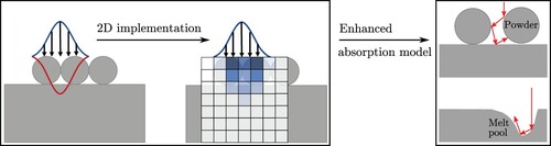
4.2.3. Multi-track and multi-layer applications
Real parts manufactured by AM are built through the layer-by-layer deposition of material, with each layer being formed by numerous laser scan vectors. shows an mm cube of 316L stainless steel with an average layer thickness of 50 μm which was 3D-printed by over 150 PBF layers, each encompassing several hundreds of scan vectors. Modelling multiple tracks and layers of PBF/DED is inevitable to linking the part-scale mechanical behaviours and defects with powder-scale local and transient phenomena.
Figure 26. 3D-printed cube of 316L fabricated by more than 150 layers of PBF and several thousands of scan vectors.
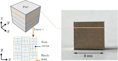
Some research teams have ventured into modelling multiple tracks and layers of metal PBF through combined DEM-CFD simulations, as shown in (C–D). Nevertheless, the utilisation of particle-based approaches for simulations of MAM remains primarily constrained to scenarios involving the melting of single tracks, with rare instances of exploring multi-track phenomena within a single layer using DEM-SPH [Citation140, Citation164], or two-dimensional multi-layer scenarios using a purely SPH solver [Citation133]. Thus, researchers are encouraged to explore a coupled DEM-SPH/OTM approach to address more expansive problem sizes, allowing for the representation of multiple tracks and layers of PBF or DED.
Figure 27. Multi-track and multi-layer MAM simulations: (A) Buildup of 10 PBF layers simulated by a 2D SPH framework in [Citation133]; (B) A coupled DEM-SPH model of PBF for a few tracks of Ti-6Al-4V PBF [Citation164]; (C) Single-track multi-layer PBF simulation of [Citation165] using DEM-CFD; and (D) Multi-track multi-layer electron beam melting simulation of [Citation78, Citation125] using a multiphysics DEM-CFD framework.
![Figure 27. Multi-track and multi-layer MAM simulations: (A) Buildup of 10 PBF layers simulated by a 2D SPH framework in [Citation133]; (B) A coupled DEM-SPH model of PBF for a few tracks of Ti-6Al-4V PBF [Citation164]; (C) Single-track multi-layer PBF simulation of [Citation165] using DEM-CFD; and (D) Multi-track multi-layer electron beam melting simulation of [Citation78, Citation125] using a multiphysics DEM-CFD framework.](/cms/asset/499b1ddd-4882-4096-a0bc-8a2a3caa8086/nvpp_a_2274494_f0027_oc.jpg)
4.2.4. In-situ alloying and multi-material applications
The allure of additive manufacturing lies in its capability to incorporate more than one material during processing, unlocking novel possibilities for tailoring desired mechanical properties and beyond. This has motivated the publication of several review papers in the past 1–2 years encompassing the general aspects of multi-material PBF/DED techniques, such as [Citation166–168], and research focussed on modelling these processes, as exemplified by Tang et al. [Citation169] and Li et al. [Citation170]. Key challenges in the modelling and simulation of MAM with more than one material are primarily rooted in the microstructural complexities and materials aspect of such processes. Multi-material PBF is currently one of the hottest research topics within the AM community, which has garnered substantial attention recently and resulted in a few notable publications on (mostly) bi-metal powder systems.
(A) showcases a 2021 publication by Wimmer et al. [Citation148], where they employed an SPH-based process simulator to predict mixing behaviour and material concentration. Another noteworthy work from the same year is the 2D lattice-Boltzmann framework of Köng et al. [Citation171] for in-situ alloying of AB with two distinct pure element powders A and B. Nonetheless, the precision, resolution, and fidelity of these process models appear to fall short of the benchmark set by single-material simulations (compare to and ), underscoring the need for further research in this burgeoning field. As an illustration of ongoing progress, a proof-of-concept PBF simulation involving 316L-Cu, utilising our multiphysics DEM-SPH solver, is presented in .
Figure 28. Recent multimaterial PBF models: (A) the 3D SPH framework of [Citation148] for a bi-metal powder system; (B) the 2D lattice-Boltzmann framework of [Citation171] for in-situ alloying of AB with two pure element powders A and B. Both works were published in 2021.
![Figure 28. Recent multimaterial PBF models: (A) the 3D SPH framework of [Citation148] for a bi-metal powder system; (B) the 2D lattice-Boltzmann framework of [Citation171] for in-situ alloying of AB with two pure element powders A and B. Both works were published in 2021.](/cms/asset/418bd518-5422-48b8-b104-a70a50fbd136/nvpp_a_2274494_f0028_oc.jpg)
Figure 29. 3D multimaterial PBF simulation using a combined DEM-SPH approach. The colour of DEM grains in the left image represents their diameter.
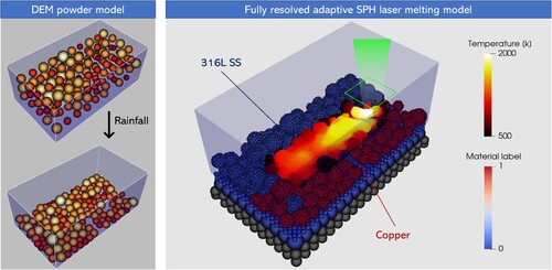
4.2.5. Integration of AI and ML techniques
The application of ML in AM can be classified into three stages with different objectives:
Pre-process
In-process
Post-process
Since process control is the ultimate goal of developing high-fidelity AM simulations in the first place, it is reasonable to anticipate that leveraging ML algorithms in the ‘in-processing’ stage would be effective and more promising. The concept of integrating simulation data into closed-loop mechanisms is a hot topic, particularly in AM. In this sense, combining meshfree particle-based simulations with feedback control is a completely unexplored area that requires original research. Given the short process times in MAM, the main challenge to achieving simulation-informed closed-loop control feedback lies in the development of ‘fast’ predictive models that can feed real-time monitoring systems.
While numerous scholars in the AM domain have shifted their research focus from traditional process modelling and simulation to ML methodologies, there remains a clear gap in the literature concerning interpretable (i.e. explainable) and generalisable data-driven ML algorithms. In the quest for a physics-based surrogate model that encompasses these qualities, an opportunity for future investigation involves exploring various neural network architectures to expedite the prediction of melt pool shapes and temperatures -- see for two recent applications. This would offer the potential to enhance the overall efficiency and accuracy of MAM simulations, without being restricted to the use of particle methods.
Figure 30. Promising applications of ML in metal additive manufacturing: (A) Prediction of melt pool dynamics and temperature using FEM and physics-informed neural networks (PINN) compared to experiment presented by Zhu et al. [Citation172]; (B) An efficient convolutional neural network architecture for fast melt pool temperature predictions in MAM that is about 5 orders of magnitude faster than Flow3D simulations, proposed by Hemmasian et al. [Citation173].
![Figure 30. Promising applications of ML in metal additive manufacturing: (A) Prediction of melt pool dynamics and temperature using FEM and physics-informed neural networks (PINN) compared to experiment presented by Zhu et al. [Citation172]; (B) An efficient convolutional neural network architecture for fast melt pool temperature predictions in MAM that is about 5 orders of magnitude faster than Flow3D simulations, proposed by Hemmasian et al. [Citation173].](/cms/asset/5150250f-8df8-4af5-8d80-90f0db4218df/nvpp_a_2274494_f0030_oc.jpg)
4.3. Outlook
The preceding sections outlined several representative areas where future research in meshfree MAM simulations could be fundamentally beneficial. The following two groups highlight the primary challenges in MAM technologies, where further development of meshfree particle-based numerical simulation frameworks can be of significant help from a more practical perspective.
Process modelling, control, and optimisation. Meshfree particle-based simulation methods provide a viable alternative to create high-fidelity models of AM processes that are potentially more efficient than existing CFD techniques for solving complex microfluid, thermo-hydrodynamics, and powder metallurgy problems. This would ultimately enable online process control by generating insights into material deposition, melting, (re)solidification, and microstructure evolution. It also allows for the optimisation of process parameters, scan strategies, and the prediction of residual stresses, distortions, and the onset of failures.
Reliable predictive tool for manufacturing quality. Meshfree process simulations need further enhancements to be considered ‘reliable predictive tools’ for assessing manufacturing defects and part quality. They will assist in identifying potential issues such as balling, cracking, and lack-of-fusion porosity. This, in turn, results in more efficient and cost-effective AM processes with fewer iterations and improved final part quality.
Basis for digital twinning. Physics-based mechanistic models of MAM are an essential component in establishing the digital twining technology, a pivotal element of modern manufacturing during the Industry 4.0 era. Seamless integration of detailed process simulations, data analytics (via ML), and in-situ sensing is imperative for achieving representative digital twins of MAM processes, facilitating real-time process monitoring.
5. Conclusion
The popularity of particle methods in solving the complex physics and material transformations inherent in MAM problems has surged significantly within the past 4–5 years. Aligned with this trend, we reviewed the recent advancements in the modelling and simulation of powder-based processes and discussed their capabilities and limitations in a systematic fashion.
The majority of existing models are tailored for fusion-based processes, namely PBF and DED, that involve powder deposition and laser-material interactions. This preference stems from the fundamental similarities in the modelling aspects of these two processes, and their prevalence in comparison to other MAM techniques, like BJ. Within this context, the number and quality of published works on PBF simulation exceed those on DED (refer to ). The DEM-SPH combination emerges as the most effective modelling approach for simulating the entire process: powder deposition, laser melting, fluid flows, and solidification. However, the current simulation capabilities are constrained to a few millimeters of scan vectors within a single layer of metal powder, utilising a (spatial) discretization resolution of 1 μm. A full DEM-SPH process simulation at this resolution would encompass over 25 million discretization particles and require approximately 4–5 days to complete, necessitating the utilisation of parallel computing techniques.
Despite the impressive capabilities of developed models, particularly in predicting melt pool behaviour, several key issues remain unresolved. Some essential phenomena, such as the vaporisation of molten metal and the resolution of fluid-solid interaction, must be incorporated into the physical models. Additionally, more accurate heat source modelling using methods like ray tracing, which is fundamental for representing keyhole formation, would increase accuracy and offer significant value. Another considerable challenge stems from the substantial computational resources required by simulations, necessitating massive parallelisation on GPU and CPU clusters. Without such parallelisation, multi-track multi-layer MAM simulations would be practically impossible. Moreover, the integration of particle-based, physics-informed MAM process models with fast ML and data-driven approaches presents exciting opportunities to shift the focus of current model development activities, leading to unprecedented computational efficiency and savings. From a material-process perspective, the integration of in-situ alloying and multi-material applications holds great potential for expanding the capabilities of MAM, enabling the use of simulation feedback in fabricating functional components with tailored material properties. In brief, the prospects of developing meshfree particle-based methods in MAM can be outlined as:
Application to assess manufacturing defects, especially lack-of-fusion porosity.
Potential to be embedded in predictive model control and in-situ process monitoring systems.
Further exploration of runtime acceleration for larger simulations.
As we navigate the landscape of MAM, it is evident that while current computational models exhibit remarkable capabilities, they also reveal various unresolved drawbacks and significant challenges. Researchers and developers in the MAM field are therefore encouraged to explore the potential of particle methods and collaborate across disciplines to maximise progress in this rapidly evolving domain. Of particular interest and importance would be the feasibility of recasting particle methods into the ML-assisted surrogate models of multiscale MAM processes, which is likely to become an integral part of digital twining, in-situ process control, optimisation, and design in the near future.
Disclosure statement
No potential conflict of interest was reported by the author(s).
References
- Standard A. Standard terminology for additive manufacturing technologies. ASTM Int F2792-12a. 2012;10.04:1–9.
- Gibson I, Rosen D, Stucker B, et al. Additive manufacturing technologies. Vol. 17. Cham (Switzerland): Springer; 2021.
- Wohlers T. Wohlers report. Wohlers Associates Inc; 2014.
- King W, Anderson AT, Ferencz RM, et al. Overview of modelling and simulation of metal powder bed fusion process at Lawrence Livermore National Laboratory. Mater Sci Technol. 2015;31(8):957–968. doi: 10.1179/1743284714Y.0000000728
- Galantucci LM, Guerra MG, Dassisti M, et al. Additive manufacturing: new trends in the 4th industrial revolution. In: Proceedings of the 4th International Conference on the Industry 4.0 Model for Advanced Manufacturing: AMP 4; Springer; 2019. p. 153–169.
- Mehrpouya M, Dehghanghadikolaei A, Fotovvati B, et al. The potential of additive manufacturing in the smart factory industrial 4.0: a review. Appl Sci. 2019;9(18):3865. doi: 10.3390/app9183865
- Koenig B. Toyota using AI, 3D printing as tools. 2022.
- Campbell I, Diegel O, Kowen J, et al. Wohlers report 2018: 3D printing and additive manufacturing state of the industry: annual worldwide progress report. 2018.
- King WE, Anderson AT, Ferencz RM, et al. Laser powder bed fusion additive manufacturing of metals; physics, computational, and materials challenges. Appl Phys Rev. 2015 Dec;2(4):041304. doi: 10.1063/1.4937809
- Yan W, Lin S, Kafka OL, et al. Modeling process-structure-property relationships for additive manufacturing. Front Mech Eng. 2018;13(4):482–492. doi: 10.1007/s11465-018-0505-y
- Yadroitsev I. Selective laser melting: direct manufacturing of 3D-objects by selective laser melting of metal powders. Saint-Etienne: LAP Lambert Academic Publishing; 2009.
- Nie P, Ojo O, Li Z. Numerical modeling of microstructure evolution during laser additive manufacturing of a nickel-based superalloy. Acta Mater. 2014;77:85–95. doi: 10.1016/j.actamat.2014.05.039
- Sahoo S, Chou K. Phase-field simulation of microstructure evolution of Ti–6Al–4V in electron beam additive manufacturing process. Addit Manuf. 2016;9:14–24.
- Khairallah SA, Anderson A. Mesoscopic simulation model of selective laser melting of stainless steel powder. J Mater Process Technol. 2014;214(11):2627–2636. doi: 10.1016/j.jmatprotec.2014.06.001
- Heeling T, Cloots M, Wegener K. Melt pool simulation for the evaluation of process parameters in selective laser melting. Addit Manuf. 2017;14:116–125.
- Wang Z, Denlinger E, Michaleris P, et al. Residual stress mapping in inconel 625 fabricated through additive manufacturing: method for neutron diffraction measurements to validate thermomechanical model predictions. Mater Des. 2017;113:169–177. doi: 10.1016/j.matdes.2016.10.003
- Williams RJ, Davies CM, Hooper PA. A pragmatic part scale model for residual stress and distortion prediction in powder bed fusion. Addit Manuf. 2018;22:416–425.
- Verma R, Kumar P, Jayaganthan R, et al. Extended finite element simulation on tensile, fracture toughness and fatigue crack growth behaviour of additively manufactured Ti6Al4V alloy. Theoret Appl Fract Mech. 2022;117:103163. doi: 10.1016/j.tafmec.2021.103163
- Markl M, Körner C. Multiscale modeling of powder bed–based additive manufacturing. Annu Rev Mater Res. 2016;46(1):93–123. doi: 10.1146/matsci.2016.46.issue-1
- Meier C, Penny RW, Zou Y, et al. Thermophysical phenomena in metal additive manufacturing by selective laser melting: fundamentals, modeling, simulation, and experimentation. Ann Rev Heat Transf. 2017;20(1):241–316. doi: 10.1615/AnnualRevHeatTransfer.v20
- Francois MM, Sun A, King WE, et al. Modeling of additive manufacturing processes for metals: challenges and opportunities. Curr Opin Solid State Mater Sci. 2017;21(4):198–206. doi: 10.1016/j.cossms.2016.12.001
- Wei H, Mukherjee T, Zhang W, et al. Mechanistic models for additive manufacturing of metallic components. Prog Mater Sci. 2021;116:100703. doi: 10.1016/j.pmatsci.2020.100703
- Luo Z, Zhao Y. A survey of finite element analysis of temperature and thermal stress fields in powder bed fusion additive manufacturing. Addit Manuf. 2018;21:318–332.
- Bayat M, Dong W, Thorborg J, et al. A review of multi-scale and multi-physics simulations of metal additive manufacturing processes with focus on modeling strategies. Addit Manuf. 2021;47:102278.
- Li E, Zhou Z, Wang L, et al. Particle scale modelling of powder recoating and melt pool dynamics in laser powder bed fusion additive manufacturing: a review. Powder Technol. 2022;409:117789. doi: 10.1016/j.powtec.2022.117789
- Wirth F. Process understanding, modeling and predictive simulation of laser cladding. Zurich (Switzerland): ETH Zurich; 2018.
- Cook PS, Murphy AB. Simulation of melt pool behaviour during additive manufacturing: underlying physics and progress. Addit Manuf. 2020 Jan;31:100909.
- Steen WM, Mazumder J. Laser material processing. London: Springer-Verlag London Ltd; 2010.
- Gu DD, Meiners W, Wissenbach K, et al. Laser additive manufacturing of metallic components: materials, processes and mechanisms. Int Mater Rev. 2012;57(3):133–164. doi: 10.1179/1743280411Y.0000000014
- Khairallah SA, Anderson AT, Rubenchik A, et al. Laser powder-bed fusion additive manufacturing: physics of complex melt flow and formation mechanisms of pores, spatter, and denudation zones. Acta Mater. 2016;108:36–45. doi: 10.1016/j.actamat.2016.02.014
- Brackbill JU, Kothe DB, Zemach C. A continuum method for modeling surface tension. J Comput Phys. 1992;100(2):335–354. doi: 10.1016/0021-9991(92)90240-Y
- Chow T. Wetting of rough surfaces. J Phys Condens Matter. 1998;10(27):L445–L451. doi: 10.1088/0953-8984/10/27/001.
- Semak V, Matsunawa A. The role of recoil pressure in energy balance during laser materials processing. J Phys D: Appl Phys. 1997;30(18):2541–2552. doi: 10.1088/0022-3727/30/18/008
- Klassen A, Scharowsky T, Körner C. Evaporation model for beam based additive manufacturing using free surface lattice boltzmann methods. J Phys D Appl Phys. 2014;47(27):275303. doi: 10.1088/0022-3727/47/27/275303
- Klassen A, Forster VE, Körner C. A multi-component evaporation model for beam melting processes. Model Simul Mater Sci Eng. 2017;25(2):025003. doi: 10.1088/1361-651X/aa5289
- Weirather J, Rozov V, Wille M, et al. A smoothed particle hydrodynamics model for laser beam melting of Ni-based alloy 718. Comput Math Appl. 2019;78(7):2377–2394.
- Gusarov A, Yadroitsev I, Bertrand P, et al. Model of radiation and heat transfer in laser-powder interaction zone at selective laser melting. ASME J Heat Transf. 2009;131(7):1–10. doi: 10.1115/1.3109245
- Hashemi H, Sliepcevich C. A numerical method for solving two-dimensional problems of heat conduction with change of phase. Chem Eng Prog Symp Ser. 1967;63:34–41.
- Kaufman L, Bernstein H. Computer calculation of phase diagrams. with special reference to refractory metals. 1970.
- Ganeriwala R, Zohdi TI. A coupled discrete element-finite difference model of selective laser sintering. Granul Matter. 2016;18(2):21. doi: 10.1007/s10035-016-0626-0
- Marshall P. Austenitic stainless steels: microstructure and mechanical properties. 1984.
- Russell M, Souto-Iglesias A, Zohdi T. Numerical simulation of laser fusion additive manufacturing processes using the SPH method. Comput Methods Appl Mech Eng. 2018;341:163–187. doi: 10.1016/j.cma.2018.06.033
- Mills KC. Recommended values of thermophysical properties for selected commercial alloys. Cambridge (England): Woodhead Publishing; 2002.
- Sahoo P, Debroy T, McNallan M. Surface tension of binary metal–surface active solute systems under conditions relevant to welding metallurgy. Metall Trans B. 1988;19(3):483–491. doi: 10.1007/BF02657748
- He X, Fuerschbach P, DebRoy T. Heat transfer and fluid flow during laser spot welding of 304 stainless steel. J Phys D Appl Phys. 2003;36(12):1388–1398. doi: 10.1088/0022-3727/36/12/306
- Wessels H, Weißenfels C, Wriggers P. Metal particle fusion analysis for additive manufacturing using the stabilized optimal transportation meshfree method. Comput Methods Appl Mech Eng. 2018;339:91–114. doi: 10.1016/j.cma.2018.04.042
- Wessels H. Thermo-mechanical modeling for selective laser melting. Institut für Kontinuumsmechanik, Gottfried Wilhelm Leibniz Universität Hannover. 2019.
- Chawla T, Graff D, Borg R, et al. Thermophysical properties of mixed oxide fuel and stainless steel type 316 for use in transition phase analysis. Nuclear Eng Des. 1981;67(1):57–74. doi: 10.1016/0029-5493(81)90155-2
- Goldak JA, Akhlaghi M. Computational welding mechanics. New York (NY): Springer Science & Business Media; 2005.
- Karditsas PJ, Baptiste M-J. Thermal and structural properties of fusion related materials. UKAEA Government Division; 1995. (Tech. rep.).
- Hodge N, Ferencz R, Solberg J. Implementation of a thermomechanical model for the simulation of selective laser melting. Comput Mech. 2014;54(1):33–51. doi: 10.1007/s00466-014-1024-2
- Neira-Arce A. Thermal modeling and simulation of electron beam melting for rapid prototyping on Ti6Al4V alloys. Ann Arbor (MI): ProQuest LLC; 2012.
- Andreotta R, Ladani L, Brindley W. Finite element simulation of laser additive melting and solidification of inconel 718 with experimentally tested thermal properties. Finite Elem Anal Des. 2017;135:36–43. doi: 10.1016/j.finel.2017.07.002
- Chen H, Wei Q, Wen S, et al. Flow behavior of powder particles in layering process of selective laser melting: numerical modeling and experimental verification based on discrete element method. Int J Mach Tools Manuf. 2017;123:146–159. doi: 10.1016/j.ijmachtools.2017.08.004
- You Y, Zhao Y. Discrete element modelling of ellipsoidal particles using super-ellipsoids and multi-spheres: a comparative study. Powder Technol. 2018;331:179–191. doi: 10.1016/j.powtec.2018.03.017
- Spierings AB, Voegtlin M, Bauer T, et al. Powder flowability characterisation methodology for powder-bed-based metal additive manufacturing. Progress Addit Manuf. 2016;1(1–2):9–20. doi: 10.1007/s40964-015-0001-4
- Dai L, Chan Y, Vastola G, et al. Characterizing the intrinsic properties of powder–a combined discrete element analysis and hall flowmeter testing study. Adv Powder Technol. 2021;32(1):80–87. doi: 10.1016/j.apt.2020.11.015
- Nguyen QB, Nai MLS, Zhu Z, et al. Characteristics of inconel powders for powder-bed additive manufacturing. Engineering. 2017;3(5):695–700. doi: 10.1016/J.ENG.2017.05.012
- Tan Y, Zhang J, Li X, et al. Comprehensive evaluation of powder flowability for additive manufacturing using principal component analysis. Powder Technol. 2021;393:154–164. doi: 10.1016/j.powtec.2021.07.069
- Lumay G, Boschini F, Traina K, et al. Measuring the flowing properties of powders and grains. Powder Technol. 2012;224:19–27. doi: 10.1016/j.powtec.2012.02.015
- Cordova L, Chen Z. Impact of powder recoating speed on built properties in PBF-LB process. Procedia CIRP. 2022;115:125–129. doi: 10.1016/j.procir.2022.10.061
- Zhang Z, Ge P, Li T, et al. Electromagnetic wave-based analysis of laser–particle interactions in directed energy deposition additive manufacturing. Addit Manuf. 2020;34:101284.
- Yao X, Zhang Z. Laser-particle interaction-based heat source model of laser powder bed fusion additive manufacturing. Opt Laser Technol. 2022;155:108402. doi: 10.1016/j.optlastec.2022.108402
- Zhang Z, Ge P, Li J, et al. Laser–particle interaction-based analysis of powder particle effects on temperatures and distortions in directed energy deposition additive manufacturing. J Therm Stresses. 2021;44(9):1068–1095. doi: 10.1080/01495739.2021.1954572
- Yao X, Li J, Wang Y, et al. Experimental and numerical studies of nozzle effect on powder flow behaviors in directed energy deposition additive manufacturing. Int J Mech Sci. 2021;210:106740. doi: 10.1016/j.ijmecsci.2021.106740
- Gao X, Yao X, Niu F, et al. The influence of nozzle geometry on powder flow behaviors in directed energy deposition additive manufacturing. Adv Powder Technol. 2022;33(3):103487. doi: 10.1016/j.apt.2022.103487
- Zohdi TI. Additive particle deposition and selective laser processing-a computational manufacturing framework. Comput Mech. 2014 Jul;54(1):171–191. doi: 10.1007/s00466-014-1012-6
- Zohdi T. Computation of the coupled thermo-optical scattering properties of random particulate systems. Comput Methods Appl Mech Eng. 2006;195(41–43):5813–5830. doi: 10.1016/j.cma.2005.04.023
- Zaeh MF, Branner G. Investigations on residual stresses and deformations in selective laser melting. Prod Eng. 2010;4(1):35–45. doi: 10.1007/s11740-009-0192-y
- Körner C, Attar E, Heinl P. Mesoscopic simulation of selective beam melting processes. Comp Part Mech. 2011;6:978–987.
- Panwisawas C, Qiu C, Anderson MJ, et al. Mesoscale modelling of selective laser melting: thermal fluid dynamics and microstructural evolution. Comput Mater Sci. 2017;126:479–490. doi: 10.1016/j.commatsci.2016.10.011
- Zohdi TI. Rapid simulation of laser processing of discrete particulate materials. Arch Comput Methods Eng. 2013;20(4):309–325. doi: 10.1007/s11831-013-9092-6
- Qiu C, Panwisawas C, Ward M, et al. On the role of melt flow into the surface structure and porosity development during selective laser melting. Acta Mater. 2015;96:72–79. doi: 10.1016/j.actamat.2015.06.004
- Panwisawas C, Sovani Y, Turner RP, et al. Modelling of thermal fluid dynamics for fusion welding. J Mater Process Technol. 2018;252:176–182. doi: 10.1016/j.jmatprotec.2017.09.019
- Yan W, Smith J, Ge W, et al. Multiscale modeling of electron beam and substrate interaction: a new heat source model. Comput Mech. 2015;56(2):265–276. doi: 10.1007/s00466-015-1170-1
- Zohdi T. On the optical thickness of disordered particulate media. Mech Mater. 2006;38(8–10):969–981. doi: 10.1016/j.mechmat.2005.06.025
- Zacarias M, Malacara-Hernández D, Malacara-Hernández Z. Handbook of optical design. Boca Raton (FL): CRC Press; 2003.
- Yan W, Ge W, Qian Y, et al. Multi-physics modeling of single/multiple-track defect mechanisms in electron beam selective melting. Acta Mater. 2017;134:324–333. doi: 10.1016/j.actamat.2017.05.061
- Yan W, Lin S, Kafka OL, et al. Data-driven multi-scale multi-physics models to derive process–structure–property relationships for additive manufacturing. Comput Mech. 2018;61(5):521–541. doi: 10.1007/s00466-018-1539-z
- Ki H, Mazumder J, Mohanty PS. Modeling of laser keyhole welding: part I. Mathematical modeling, numerical methodology, role of recoil pressure, multiple reflections, and free surface evolution. Metall Mater Trans A. 2002;33(6):1817–1830. doi: 10.1007/s11661-002-0190-6
- Otto A, Koch H, Vazquez RG. Multiphysical simulation of laser material processing. Phys Proc. 2012;39:843–852. doi: 10.1016/j.phpro.2012.10.109
- Gürtler F, Karg M, Dobler M, et al. Influence of powder distribution on process stability in laser beam melting: analysis of melt pool dynamics by numerical simulations. In: International Solid Freeform Fabrication Symposium; Austin (TX). 2014. p. 1099–1117.
- Lee Y, Zhang W. Modeling of heat transfer, fluid flow and solidification microstructure of nickel-base superalloy fabricated by laser powder bed fusion. Addit Manuf. 2016;12:178–188.
- Liu B, Fang G, Lei L, et al. A new ray tracing heat source model for mesoscale CFD simulation of selective laser melting (SLM). Appl Math Model. 2020;79:506–520. doi: 10.1016/j.apm.2019.10.049
- Hu H, Eberhard P. Thermomechanically coupled conduction mode laser welding simulations using smoothed particle hydrodynamics. Comput Particle Mech. 2017;4(4):473–486. doi: 10.1007/s40571-016-0140-5
- Wessels H, Bode T, Weißenfels C, et al. Investigation of heat source modeling for selective laser melting. Comput Mech. 2019 May;63(5):949–970. doi: 10.1007/s00466-018-1631-4
- Gürtler F-J, Karg M, Leitz K-H, et al. Simulation of laser beam melting of steel powders using the three-dimensional volume of fluid method. Phys Procedia. 2013;41:881–886. doi: 10.1016/j.phpro.2013.03.162
- Megahed M, Mindt H-W, N'Dri N, et al. Metal additive-manufacturing process and residual stress modeling. Integ Mater Manuf Innov. 2016;5(1):61–93. doi: 10.1186/s40192-016-0047-2
- Liu M, Liu G. Smoothed particle hydrodynamics (sph): an overview and recent developments. Arch Comput Methods Eng. 2010;17(1):25–76. doi: 10.1007/s11831-010-9040-7
- Shadloo MS, Oger G, Le Touzé D. Smoothed particle hydrodynamics method for fluid flows, towards industrial applications: motivations, current state, and challenges. Comput Fluids. 2016;136:11–34. doi: 10.1016/j.compfluid.2016.05.029
- Violeau D, Rogers BD. Smoothed particle hydrodynamics (sph) for free-surface flows: past, present and future. J Hydraul Res. 2016;54(1):1–26. doi: 10.1080/00221686.2015.1119209
- Fürstenau J-P, Wessels H, Weißenfels C, et al. Generating virtual process maps of slm using powder-scale sph simulations. Comput Part Mech. 2020;7(4):655–677. doi: 10.1007/s40571-019-00296-3
- Fan Z, Wang H, Huang Z, et al. A lagrangian meshfree mesoscale simulation of powder bed fusion additive manufacturing of metals. Int J Numer Methods Eng. 2021;122(2):483–514. doi: 10.1002/nme.v122.2
- Dao MH, Lou J. Simulations of laser assisted additive manufacturing by smoothed particle hydrodynamics. Comput Methods Appl Mech Eng. 2021;373:113491. doi: 10.1016/j.cma.2020.113491
- Dao MH, Lou J. Simulations of directed energy deposition additive manufacturing process by smoothed particle hydrodynamics methods. Int J Adv Manuf Technol. 2022;120(7-8):4755–4774. doi: 10.1007/s00170-022-09050-1
- Meier C, Fuchs SL, Hart AJ, et al. A novel smoothed particle hydrodynamics formulation for thermo-capillary phase change problems with focus on metal additive manufacturing melt pool modeling. Comput Methods Appl Mech Eng. 2021;381:113812. doi: 10.1016/j.cma.2021.113812
- Fuchs SL, Praegla PM, Cyron CJ, et al. A versatile sph modeling framework for coupled microfluid-powder dynamics in additive manufacturing: binder jetting, material jetting, directed energy deposition and powder bed fusion. Eng Comput. 2022;38:4853–4877. doi: 10.1007/s00366-022-01724-4
- Körner C, Attar E, Heinl P. Mesoscopic simulation of selective beam melting processes. J Mater Process Technol. 2011;211(6):978–987. doi: 10.1016/j.jmatprotec.2010.12.016
- Maeshima T, Kim Y, Zohdi TI. Particle-scale numerical modeling of thermo-mechanical phenomena for additive manufacturing using the material point method. Comput Part Mech. 2021;8(3):613–623. doi: 10.1007/s40571-020-00358-x
- Cundall PA, Strack OD. A discrete numerical model for granular assemblies. Geotechnique. 1979;29(1):47–65. doi: 10.1680/geot.1979.29.1.47
- Monaghan J. Sph and riemann solvers. J Comput Phys. 1997;136(2):298–307. doi: 10.1006/jcph.1997.5732
- Lucy LB. A numerical approach to the testing of the fission hypothesis. Astron J. 1977;82:1013–1024. doi: 10.1086/112164
- Liu G-R, Liu MB. Smoothed particle hydrodynamics: a meshfree particle method. Singapore: World Scientific; 2003.
- Afrasiabi M, Roethlin M, Wegener K. Contemporary meshfree methods for three dimensional heat conduction problems. Arch Comput Methods Eng. 2020 Nov;27(5):1413–1447. doi: 10.1007/s11831-019-09355-7
- Li B, Habbal F, Ortiz M. Optimal transportation meshfree approximation schemes for fluid and plastic flows. Int J Numer Methods Eng. 2010;83(12):1541–1579. doi: 10.1002/nme.2869
- Weißenfels C, Wriggers P. Stabilization algorithm for the optimal transportation meshfree approximation scheme. Comput Methods Appl Mech Eng. 2018;329:421–443. doi: 10.1016/j.cma.2017.09.031
- Wang H, Liao H, Fan Z, et al. The hot optimal transportation meshfree (hotm) method for materials under extreme dynamic thermomechanical conditions. Comput Methods Appl Mech Eng. 2020;364:112958. doi: 10.1016/j.cma.2020.112958
- Chen H, Wei Q, Zhang Y, et al. Powder-spreading mechanisms in powder-bed-based additive manufacturing: experiments and computational modeling. Acta Mater. 2019;179:158–171. doi: 10.1016/j.actamat.2019.08.030
- Han Q, Gu H, Setchi R. Discrete element simulation of powder layer thickness in laser additive manufacturing. Powder Technol. 2019;352:91–102. doi: 10.1016/j.powtec.2019.04.057
- Meier C, Weissbach R, Weinberg J, et al. Critical influences of particle size and adhesion on the powder layer uniformity in metal additive manufacturing. J Mater Process Technol. 2019;266:484–501. doi: 10.1016/j.jmatprotec.2018.10.037
- Dai L, Chan Y, Vastola G, et al. Discrete element simulation of powder flow in revolution powder analyser: effects of shape factor, friction and adhesion. Powder Technol. 2022;408:117790. doi: 10.1016/j.powtec.2022.117790
- Yim S, Bian H, Aoyagi K, et al. Spreading behavior of Ti48Al2Cr2Nb powders in powder bed fusion additive manufacturing process: experimental and discrete element method study. Addit Manuf. 2022;49:102489.
- Lee Y, Gurnon AK, Bodner D, et al. Effect of particle spreading dynamics on powder bed quality in metal additive manufacturing. Integ Mater Manuf Innovat. 2020;9(4):410–422. doi: 10.1007/s40192-020-00193-1
- Ganesan VV, Amerinatanzi A, Jain A. Discrete element modeling (DEM) simulations of powder bed densification using horizontal compactors in metal additive manufacturing. Powder Technol. 2022;405:117557. doi: 10.1016/j.powtec.2022.117557
- Sehhat MH, Mahdianikhotbesara A. Powder spreading in laser-powder bed fusion process. Granul Matter. 2021;23(4):89. doi: 10.1007/s10035-021-01162-x
- Lee Y, Nandwana P, Zhang W. Dynamic simulation of powder packing structure for powder bed additive manufacturing. Int J Adv Manuf Technol. 2018;96(1-4):1507–1520. doi: 10.1007/s00170-018-1697-3
- Nan W, Pasha M, Bonakdar T, et al. Jamming during particle spreading in additive manufacturing. Powder Technol. 2018;338:253–262. doi: 10.1016/j.powtec.2018.07.030
- Nan W, Ghadiri M. Numerical simulation of powder flow during spreading in additive manufacturing. Powder Technol. 2019;342:801–807. doi: 10.1016/j.powtec.2018.10.056
- Fouda YM, Bayly AE. A dem study of powder spreading in additive layer manufacturing. Granul Matter. 2020;22(1):1–18. doi: 10.1007/s10035-019-0971-x
- Yim S, Bian H, Aoyagi K, et al. Effect of powder morphology on flowability and spreading behavior in powder bed fusion additive manufacturing process: a particle-scale modeling study. Addit Manuf. 2023;72:103612.
- Bouabbou A, Vaudreuil S. Numerical modelling of SS316L powder flowability for laser powder-bed fusion. Arch Mater Sci Eng. 2023;120(1):22–29. doi: 10.5604/18972764
- Yan Z, Wilkinson SK, Stitt EH, et al. Investigating mixing and segregation using discrete element modelling (DEM) in the freeman FT4 rheometer. Int J Pharm. 2016;513(1–2):38–48. doi: 10.1016/j.ijpharm.2016.08.065
- Wilkinson S, Turnbull S, Yan Z, et al. A parametric evaluation of powder flowability using a freeman rheometer through statistical and sensitivity analysis: a discrete element method (DEM) study. Comput Chem Eng. 2017;97:161–174. doi: 10.1016/j.compchemeng.2016.11.034
- Steuben JC, Iliopoulos AP, Michopoulos JG. Discrete element modeling of particle-based additive manufacturing processes. Comput Methods Appl Mech Eng. 2016;305:537–561. doi: 10.1016/j.cma.2016.02.023
- Yan W, Qian Y, Ge W, et al. Meso-scale modeling of multiple-layer fabrication process in selective electron beam melting: inter-layer/track voids formation. Mater Des. 2018;141:210–219. doi: 10.1016/j.matdes.2017.12.031
- Chen H, Sun Y, Yuan W, et al. A review on discrete element method simulation in laser powder bed fusion additive manufacturing. Chin J Mech Eng Addit Manuf Front. 2022;1:100017.
- Ma H, Zhou L, Liu Z, et al. A review of recent development for the cfd-dem investigations of non-spherical particles. Powder Technol. 2022;412:117972. doi: 10.1016/j.powtec.2022.117972
- Rong D, Horio M. Dem simulation of char combustion in a fluidized bed. In: Second International Conference on CFD in the Minerals and Process Industries CSIRO; Melbourne, Australia; 1999. p. 65–70.
- Zhou Z, Yu A, Zulli P. A new computational method for studying heat transfer in fluid bed reactors. Powder Technol. 2010;197(1–2):102–110. doi: 10.1016/j.powtec.2009.09.002
- Peng Z, Doroodchi E, Moghtaderi B. Heat transfer modelling in discrete element method (dem)-based simulations of thermal processes: theory and model development. Prog Energy Combust Sci. 2020;79:100847. doi: 10.1016/j.pecs.2020.100847
- Liu S, Liu J, Chen J, et al. Influence of surface tension on the molten pool morphology in laser melting. Int J Therm Sci. 2019;146:106075. doi: 10.1016/j.ijthermalsci.2019.106075
- Afrasiabi M, Lüthi C, Bambach M, et al. Multi-resolution sph simulation of a laser powder bed fusion additive manufacturing process. Appl Sci. 2021;11(7):1. doi: 10.3390/app11072962
- Afrasiabi M, Lüthi C, Bambach M, et al. Smoothed particle hydrodynamics modeling of the multi-layer laser powder bed fusion process. Procedia CIRP. 2022;107:276–282. doi: 10.1016/j.procir.2022.04.045
- Liu S, Liu J, Qi L, et al. Simulation of the temperature distribution and solidified bead in single-pass selective laser melting using a mesh-free method. J Appl Phys. 2019;126(13):133104. doi: 10.1063/1.5096041
- Qiu Y, Niu X, Song T, et al. Three-dimensional numerical simulation of selective laser melting process based on sph method. J Manuf Process. 2021;71:224–236. doi: 10.1016/j.jmapro.2021.09.018
- Meier C, Fuchs SL, Much N, et al. Physics-based modeling and predictive simulation of powder bed fusion additive manufacturing across length scales. GAMM-Mitteilungen. 2021;44(3):e202100014. doi: 10.1002/gamm.v44.3
- Park CY, Zohdi TI. Numerical modeling of thermo-mechanically induced stress in substrates for droplet-based additive manufacturing processes. J Manuf Sci Eng. 2019;141(6):061001. doi: 10.1115/1.4043254
- Trautmann M, Hertel M, Füssel U. Numerical simulation of TIG weld pool dynamics using smoothed particle hydrodynamics. Int J Heat Mass Transf. 2017;115:842–853. doi: 10.1016/j.ijheatmasstransfer.2017.08.060
- Afrasiabi M, Keller D, Lüthi C, et al. Effect of process parameters on melt pool geometry in laser powder bed fusion of metals: a numerical investigation. Procedia CIRP. 2022;113:378–384. doi: 10.1016/j.procir.2022.09.187
- Lüthi C, Afrasiabi M, Bambach M. An adaptive smoothed particle hydrodynamics (SPH) scheme for efficient melt pool simulations in additive manufacturing. Comput Math Appl. 2023;139:7–27.
- Fan Z, Li B. Meshfree simulations for additive manufacturing process of metals. Integr Mater Manuf Innov. 2019;8(2):144–153. doi: 10.1007/s40192-019-00131-w
- Wessels H, Bode T, Weißenfels C, et al. Investigation of heat source modeling for selective laser melting. Comput Mech. 2019;63(5):949–970. doi: 10.1007/s00466-018-1631-4
- He X, Luo L-S. A priori derivation of the lattice Boltzmann equation. Phys Rev E. 1997;55(6):R6333–R6336. doi: 10.1103/PhysRevE.55.R6333
- Ammer R, Markl M, Ljungblad U, et al. Simulating fast electron beam melting with a parallel thermal free surface lattice Boltzmann method. Comput Math Appl. 2014;67(2):318–330. doi: 10.1016/j.camwa.2013.10.001
- Miyanaji H, Zhang S, Yang L. A new physics-based model for equilibrium saturation determination in binder jetting additive manufacturing process. Int J Mach Tools Manuf. 2018;124:1–11. doi: 10.1016/j.ijmachtools.2017.09.001
- Deng H, Huang Y, Wu S, et al. Binder jetting additive manufacturing: three-dimensional simulation of micro-meter droplet impact and penetration into powder bed. J Manuf Process. 2022;74:365–373. doi: 10.1016/j.jmapro.2021.12.019
- Yang Z, Zhang Y, Yan W. High-fidelity modeling of binder-powder interactions in binder jetting: binder flow and powder dynamics. Acta Mater. 2023;260:119298. doi: 10.1016/j.actamat.2023.119298
- Wimmer A, Yalvac B, Zoeller C, et al. Experimental and numerical investigations of in situ alloying during powder bed fusion of metals using a laser beam. Metals. 2021;11(11):1842. doi: 10.3390/met11111842
- Flow-3D A. FlOW-3D am. [Accessed 2023 July 10].
- Pryor RW. Multiphysics modeling using COMSOL 5 and MATLAB. Mercury learning and information. 2021.
- De Vaucorbeil A, Nguyen VP, Sinaie S, et al. Material point method after 25 years: theory, implementation, and applications. Adv Appl Mech. 2020;53:185–398. doi: 10.1016/bs.aams.2019.11.001
- Oñate E, Idelsohn SR, Del Pin F, et al. The particle finite element method–an overview. Int J Comput Methods. 2004;01(02):267–307. doi: 10.1142/S0219876204000204
- Zhang D, Rodriguez J, Ye X, et al. A particle finite element method for additive manufacturing simulations. J Comput Inf Sci Eng. 2023;23(5):051008. doi: 10.1115/1.4062143
- Chen J, Beraun J, Carney T. A corrective smoothed particle method for boundary value problems in heat conduction. Int J Numer Methods Eng. 1999;46(2):231–252. doi: 10.1002/(ISSN)1097-0207
- Liu WK, Jun S, Zhang YF. Reproducing kernel particle methods. Int J Numer Methods Fluids. 1995;20(8-9):1081–1106. doi: 10.1002/fld.v20:8/9
- Fatehi R, Manzari M. Error estimation in smoothed particle hydrodynamics and a new scheme for second derivatives. Comput Math Appl. 2011;61(2):482–498.
- Afrasiabi M, Wegener K. 3D thermal simulation of a laser drilling process with meshfree methods. J Manuf Mater Process. 2020 Jun;4:58.
- Yu T, Zhao J. Semi-coupled resolved CFD–DEM simulation of powder-based selective laser melting for additive manufacturing. Comput Methods Appl Mech Eng. 2021;377:113707. doi: 10.1016/j.cma.2021.113707
- Vignjevic R, Reveles JR, Campbell J. SPH in a total lagrangian formalism. CMC-Tech Sci Press. 2006;4(3):181.
- Islam MRI, Peng C. A total lagrangian sph method for modelling damage and failure in solids. Int J Mech Sci. 2019;157–158:498–511. doi: 10.1016/j.ijmecsci.2019.05.003
- Wang L, Xu F, Yang Y. An improved total lagrangian SPH method for modeling solid deformation and damage. Eng Anal Bound Elem. 2021;133:286–302. doi: 10.1016/j.enganabound.2021.09.010
- Hu X, Adams NA. An incompressible multi-phase SPH method. J Comput Phys. 2007;227(1):264–278. doi: 10.1016/j.jcp.2007.07.013
- Yu T, Zhao J. Quantitative simulation of selective laser melting of metals enabled by new high-fidelity multiphase, multiphysics computational tool. Comput Methods Appl Mech Eng. 2022;399:115422. doi: 10.1016/j.cma.2022.115422
- Cummins S, Cleary PW, Delaney G, et al. A coupled dem/sph computational model to simulate microstructure evolution in Ti-6Al-4V laser powder bed fusion processes. Metals. 2021;11(6):858. doi: 10.3390/met11060858
- Cao L, Guan W. Simulation and analysis of LPBF multi-layer single-track forming process under different particle size distributions. Int J Adv Manuf Technol. 2021;114(7-8):2141–2157. doi: 10.1007/s00170-021-06987-7
- Mehrpouya M, Tuma D, Vaneker T, et al. Multimaterial powder bed fusion techniques. Rapid Prototyp J. 2022;28(11):1–19. doi: 10.1108/RPJ-01-2022-0014
- Wang D, Liu L, Deng G, et al. Recent progress on additive manufacturing of multi-material structures with laser powder bed fusion. Virtual Phys Prototyp. 2022;17(2):329–365. doi: 10.1080/17452759.2022.2028343
- Feenstra D, Banerjee R, Fraser H, et al. Critical review of the state of the art in multi-material fabrication via directed energy deposition. Curr Opin Solid State Mater Sci. 2021;25(4):100924. doi: 10.1016/j.cossms.2021.100924
- Tang C, Yao L, Du H. Computational framework for the simulation of multi material laser powder bed fusion. Int J Heat Mass Transf. 2022;191:122855. doi: 10.1016/j.ijheatmasstransfer.2022.122855
- Li W, Kishore M, Zhang R, et al. Comprehensive studies of SS316L/IN718 functionally gradient material fabricated with directed energy deposition: multi-physics & multi-materials modelling and experimental validation. Addit Manuf. 2023;61:103358.
- Küng VE, Scherr R, Markl M, et al. Multi-material model for the simulation of powder bed fusion additive manufacturing. Comput Mater Sci. 2021;194:110415. doi: 10.1016/j.commatsci.2021.110415
- Zhu Q, Liu Z, Yan J. Machine learning for metal additive manufacturing: predicting temperature and melt pool fluid dynamics using physics-informed neural networks. Comput Mech. 2021;67:619–635. doi: 10.1007/s00466-020-01952-9
- Hemmasian A, Ogoke F, Akbari P, et al. Surrogate modeling of melt pool temperature field using deep learning. Addit Manuf Lett. 2023;5:100123. doi: 10.1016/j.addlet.2023.100123