
 ?Mathematical formulae have been encoded as MathML and are displayed in this HTML version using MathJax in order to improve their display. Uncheck the box to turn MathJax off. This feature requires Javascript. Click on a formula to zoom.
ABSTRACT
As global CO2 concentrations rise, there is a pressing need for sustainable alternatives in the construction sector as many countries are striving to attain net carbon neutrality. Integrating carbon capture and sequestration (CCS) technologies directly into 3D concrete printing offer a promising solution to reduce the carbon footprint in the construction sector. This paper investigates a novel printing technique involving the purging of pressurised CO2 gas was demonstrated and the various process parameters were evaluated for its effectiveness in promoting carbon sequestration. Results show that the carbon-sequestrated sample has a 15% increase in carbon uptake as compared to the control sample. The method can be complementary to existing sequestration technologies, facilitating large-scale carbon sequestration without chamber size limitations. Nevertheless, further research and development are necessary to optimise the various printing parameters and achieve a more balanced and efficient integration of carbon capture and sequestration technologies with 3DCP.
1. Introduction
Carbon Capture and Storage (CCS) is an approach that has been researched to address the rising levels of atmospheric CO2 [Citation1]. In recent years, research on CCS has significantly intensified as efforts to combat the ongoing rise in CO2 levels have grown. Much of the focus in carbon storage research has been on geologic carbon storage (GCS), involving the sequestration of compressed CO2 in subterranean geologic formations like saline aquifers, depleted oil and gas fields, and unmineable coal seams [Citation2]. However, GCS presents various uncertainties and potential risks, including issues of permanence, the need for long-term monitoring, and verification [Citation3]. These concerns arise from the possibility of CO2 leakage, which can occur gradually or due to a significant system failure, potentially negating the benefits of the capture process. Furthermore, the buildup of pressure underground may result in minor seismic activity [Citation4]. Alternatively, carbon capture, utilisation, and storage (CCUS) through carbon mineralisation can be employed to mitigate risks and ensure long-term carbon storage. According to Zhang et al., carbonate minerals offer an ideal choice for this method [Citation5]. In 2019, the National Academies of Sciences Engineering Medicine (NASEM) reported that carbon mineralisation offers various potential benefits for both human health and the environment. These include reducing atmospheric CO2 levels, enhancing air and water quality, improving soil fertility, and creating new economic opportunities [Citation6]. In a 2019 report authored by Bobeck et al. [Citation7] from the Centre for Climate and Energy Solutions (C2ES), it was noted that carbon utilisation has the potential to reduce CO2 emissions in the global concrete and aggregates market by 1.4–3.6 billion tons, respectively. This reduction would be significant given the expected growth of concrete and aggregates by 2030, estimated to reach around 40 and 50 billion tons, respectively [Citation7].
In the cementitious product industries, a technique that has been utilised since the nineteenth century involves the use of CO2 gas curing chambers to accelerate the hydration process of cementitious materials. According to Hills et al. [Citation8], James L. Rowland was one of the pioneers who employed this method. When CO2 reacts with the alkaline compounds in concrete, such as portlandite and/or hydrated calcium silicate (C–S-H) gel, a chemical reaction is induced, resulting in the formation of calcium carbonate (CaCO3) [Citation9]. This process is known as carbonation. The carbonation reaction reduces the pH value of the concrete to about 8.5–10 [Citation9–11]. At this low pH value, CO2 reacts with calcium hydroxide (CH) and calcium silicate hydrate (C–S–H) to form calcite, which has low solubility and precipitates within the concrete pores, altering the concrete’s properties. While carbonation exposure can contribute to the corrosion of steel reinforcement, it is noteworthy that carbonation-induced corrosion typically proceeds at a significantly slower rate compared to chloride-induced corrosion [Citation12]. This can be attributed to the chemical reactions initiated by carbonation, which leads to the formation of a protective layer of calcium carbonate (CaCO3) on the surface of concrete, and can reduce chloride ingress and subsequently mitigate the corrosion of steel reinforcement [Citation13,Citation14]. Through carbonation, the concrete's properties are altered, reducing porosity, pore size distribution, permeability, and diffusion, while enhancing mechanical properties such as tensile and compressive strength, electrical resistivity, and reducing chloride penetration [Citation11].
3D Concrete Printing (3DCP) is widely recognised as a sustainable solution due to its ability to manufacture optimised designs and minimise waste [Citation15]. Recent studies by Nguyen et al. [Citation16] and Barjuei et al. [Citation17] have demonstrated the potential for further enhancement of the 3D printing process through the integration of machine learning and monitoring systems. These advancements have resulted in streamlined processes that reduce time and effort, while also improving print accuracy. By optimising the manufacturing process, these researchers have contributed to the overall quality and sustainability of 3D concrete printing. Yet despite the advantages of 3DCP, there still is room for further reduction of its carbon footprint. 3DCP mixtures, in order to satisfy printability requirements, tend to comprise of higher cement contents than those of traditional cast concrete. A common approach to reduce its carbon footprint would be the partial if not full replacement of OPC with greener alternatives, such as Supplementary Cementitious Materials (SCMs) for alkali-activated Geopolymer concrete [Citation18,Citation19]. Several SCM examples include industrial by-products such as silica fume, fly ash, and slag, which are capable of exhibiting similar if not improved durability and strength as compared to conventional concrete [Citation18]. On the other hand, existing literature has shown that replacing sand with more sustainable aggregates or optimising the aggregates-to-paste ratio can make a significant contribution towards sustainable construction, paving the way for circularity in 3D concrete printing [Citation20,Citation21]. The choice of materials plays a crucial role in determining the environmental impact and overall sustainability of the printed structures [Citation22]. By utilising sustainable materials, such as low-carbon cementitious binders, employing solid waste as aggregate replacement, or sequestrating carbon in the material, the advantages of 3D concrete printing can be further amplified.
Methods aimed at achieving carbon sequestration in cementitious products typically involve subjecting precast concrete, cast-in-place concrete, 3D printed concrete, and/or their aggregates to chamber curing under specific conditions of elevated temperature, pressure, humidity, and concentrated CO2 [Citation23–25]. To improve the CO2 sequestration level, additional parameters such as CO2 injection during the mixing phase and addition of carbonated cement paste into the mixture design have been explored [Citation26–29]. Combining both carbonation mixing and curing techniques have demonstrated a significant increase in CO2 uptake in paste samples, surpassing 10% compared to curing-only treatments [Citation27]. However, despite the positive findings reported in some studies, concerns remain regarding the time and energy consumption associated with accelerated carbonation methods using pressurised camber or chamber curing. These factors may pose compatibility challenges when implementing automated technologies like 3D concrete printing (3DCP). Monte Carlo simulations conducted by Ravikumar et al., using published experimental datasets, have also projected a higher probability of increased CO2 footprints with the utilisation of CO2 in concrete curing or mixing [Citation30]. Considering the unique characteristics of 3DCP structures, which can be constructed with a hollow lattice-designed cross-section [Citation31], they inherently offer a larger surface area exposed to CO2 compared to solid cast concrete. Moreover, adjustments in print parameters such as layer height or stand-off distance can further optimise the material’s compaction and porosity [Citation32], which are crucial for achieving CO2 ingress and mineralisation objectives. Therefore, the simultaneous introduction of CO2 gas and steam while altering these parameters may prove to be a more efficient and complementary approach to 3DCP, potentially surpassing the limitations of post-chamber curing techniques.
This research aims to investigate the potential and effects of sequestering CO2 directly into 3D printable concrete through the application of a novel printing technique, which seeks to function as a preliminary concept that encourages further development and integration of Carbon Capture and Sequestration (CCS) technologies with 3DCP. The applied methodology herein entails a direct purging of pressurised CO2 gas and vaporised water across the surface of each filament layer via a custom-built gantry printhead system. Various configurations of the experimental setup will be analysed to evaluate its effectiveness in promoting carbon sequestration with cementitious material during its printing phase. Samples extracted from the bulk of printed concrete will be subjected to thermogravimetric analysis (TGA) tests to determine the presence and quantity of mineralised carbonates after a 28-day curing period. This corresponds to the degree of carbon uptake in samples associated with its respective print configuration. While the integration of CO2 concept is patented by Saudi Aramco [Citation33], to the best of authors’ knowledge, there is a lack of studies conducted to investigate the impacts of integrating CCS technologies with 3DCP. The purpose of this study is therefore to serve as an initiative for further academic exploration and research in this domain.
2. Experimental program
2.1. Material preparation and curing conditions
The raw materials used in the study were ordinary Portland cement (OPC, ASTM Type 1), silica Fume (Undensified, Elkem), superplasticiser and river sand. The same mixture will be used for all prints. For consistency of the experiments, mixing procedures for all concrete admixtures are required to adhere to the same set of guidelines. First, all powder elements (i.e. aggregates and cementitious powder) will be dry mixed at low speeds, via a force action mixer (SoRoTo 80L mixer), for 3 min before hydrating solutions such as water, and superplasticizers are gradually added. This is to ensure even dispersion and distribution of solid particles/powder, after which 10 min of high-speed mixing will be carried out until homogeneity of the mixture is achieved. Information on the percentage of each raw material used in this study cannot be disclosed due to the non-disclosure agreement with the collaborators. Nevertheless, the primary focus of this manuscript lies in examining the impact of the CO2 sequestration process rather than on the specifics of the material composition. While it's true that different mixtures may exhibit unique characteristics, the underlying principles should remain consistent.
The samples were cured in lab conditions and were wrapped in a clear plastic to prevent water from escaping due to evaporation. The wrapped samples were exposed to lab conditions at 25°C and relative humidity of 60%. In this study, different abbreviation, as shown in , was given to the different printing process investigated to simplify the naming of the sample.
Table 1. Abbreviation for the different samples.
2.2. Printing parameters
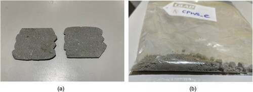
A three-axis gantry printer and a progressive cavity pump are used as the printer setup in the study. The travel speed of the nozzle was set at 100 mm/s and the material flow rate was set 39 ml/s for all experiments to ensure consistency. The nozzle orifice was a square nozzle of 20 mm. The material is delivered from the material reservoir to the nozzle by a three-meter hose. The printing speed of the gantry is fixed at 100 mm/s for all mixtures. (a) shows the different samples printed within the same batch of materials. (b) shows the front and rear sections of the print path. It is differentiated into the front and rear sections which is important due to the placement of the CO2 nozzle.
Figure 1. (a) 3D printed sample for TGA and mechanical analysis; (b) Top view of the printing path to differentiate the front and rear half of the sample; Schematic diagram for the print path with dimensions for (c) TGA and compressive strength test and (d) flexural strength test.
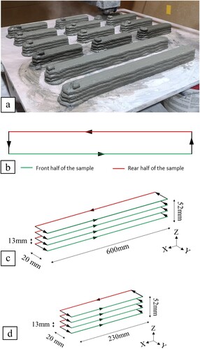
(c,d) shows the schematic diagram of the print path for the samples used for TGA test, compressive strength test and flexural strength test. After the printing process, the printed blocks using the print path shown in (c) were cut into smaller sections with the length of 50 and 1 mm for the compressive strength test and TGA test, respectively, using a diamond cutter (Struers, Secotom-60). The whole printing experiment took less than 30 mins after the cementitious mixture material were poured into the pump’s hopper.
All specimens have a solidity ratio (SR) in the range of 0.95–1.05. SR can be used to determine the consistency of the printed filament based on the printing parameters [Citation34]. Two different printing parameters can have the same SR which means the amount of material deposited per unit length is the same. SR is defined by Equation (1).
(1)
(1) where An is the area of the nozzle orifice, Vn is travel speed, and Q is the flow rate of the material.
2.3. CO2 jetting (CJ) method
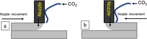
The CO2 jetting method was carried out by directly jetting CO2 on the top surface of the printed filament. By directly jetting CO2 on the different filaments, it was hypothesised to increase the CO2 uptake. This approach involves positioning a single CO2 nozzle alongside the concrete nozzle, with the outlet of the CO2 nozzle located directly above the concrete filament. This enables the injection of CO2 into the filament, facilitating concrete sequestration as it prints. The carbon dioxide gas used in this research has a purity of 99.998%. Due to the proximity of the nozzle and the high flow of CO2 blowing directly on the top surface of the filament, some of the material tended to be blown off. The pressure from the CO2 gas cylinder is fixed at 3 bar. The pressure was set at 3 bar to ensure the highest amount of CO2 was penetrating the cement filament during printing while ensuring that the pressure from the CO2 nozzle outlet is not blowing too much filament material away. shows the schematic diagram on the side view of the printing setup for a single CO2 nozzle attached printing the front and rear half of the sample. Due to the setup of the nozzle the CO2 applied to the surface is different, for the front half of the sample, CO2 is applied to the bottom of the layer, whereas for the rear half of the sample, CO2 is applied to the top surface of the filament.
Figure 2. Schematic diagram on the side view of printing with concrete and CO2 jetting nozzle for the (a) front half of the sample (b) rear half of the sample.
2.4. CO2 jetting at elevated temperature (CJET) and CO2 with steam printing (CJS)
It is being shown in existing literature that increasing the temperature can improve the carbon sequestration [Citation35]. The presence of higher humidity at elevated temperature has shown potential to enhance the CO2 uptake in the cementitious samples [Citation36]. Therefore, additional changes to CJ printing method were examined. and illustrate an alternative approach to carbon sequestration by introducing heat and steam, respectively. As shown in , the CO2 was passed through a pneumatic tube with a portion of the pneumatic tube submerged in a pot filled with boiling water. The end of the pneumatic hose is measured to be an estimated of 40°C. Similar to CJ method, the CJET method was carried out by directly jetting CO2 on the top surface of the printed filament. The printing of the front and rear half of the sample is shown in .
Figure 3. Schematic side view diagram of CJET printing method.
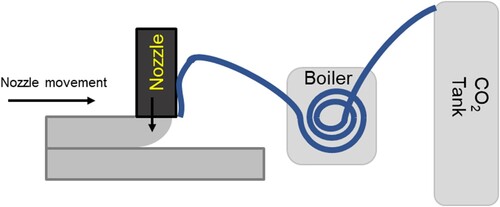
Figure 4. Schematic diagram on the side view of printing with concrete and CO2 jetting with steam for the (a) front half of the sample (b) rear half of the sample.
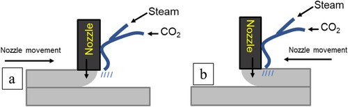
shows the steam installed to elevate the temperature of the CO2 during printing. The temperature of the steamer is fixed at approximately 100°C at the outlet of the steamer. Similar to the set up and working principle elaborated in Section 2.3 and in , shows the schematic diagram for the printing setup of the CO2 jetting nozzle and the steam nozzle. The non-rotating attachment can affect where the steam and CO2 are applied to the printed filament.
2.5. Thermogravimetric analysis test
The mass of the specimens to be placed in the equipment must be between 10 and 20 mg. To obtain samples for analysis in the CJ method, the concrete specimens were chipped from the centre of the cross section using a hammer. The resulting debris from the chippings was then pulverised into fine samples. The test specimens will be heated over a range of temperature from 20°C – 950°C at a constant rate of 10°C/min in a nitrogen atmosphere. Presence, phase, and quantity of stable carbonates (i.e. CaCO3) precipitated in each sample is determined by its mass loss percentage across a temperature range from 520°C – 950°C and the temperature can be calculated using Equations (2)–(4) [Citation31]:
(2)
(2)
(3)
(3)
(4)
(4) where %mCaCO3,DC is the percentage mass loss of the poorly crystallised CaCO3, %mCaCO3,HC is the percentage mass loss of the highly crystallised CaCO3, and %mCaCO3,Net is the net percentage mass loss of crystallised CaCO3.
2.6. Mechanical strength testing
The mechanical strength was carried out on 28 days of curing to investigate the effect of carbonation curing on the strength of the concrete. This test aims to obtain the strength characteristics of the different printing and curing conditions of the samples and therefore they were compared to the control sample. Kim et al. showed an increase in the strength when CO2 is used for curing [Citation36]. This is mainly due to the reduction in the pore size due to carbonation curing [Citation36]. The procedure for testing its mechanical strength is in accordance with the ASTM standards C109 [Citation37] ().
Figure 5. Alternative approach for TGA sample preparation; (a) Sliced sample; (b) Sliced sample pulverised into fine powders.
3. Results and discussion
3.1. Evaluation of CO2 jetting with different configurations
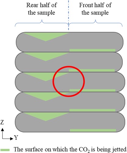
All carbon jetted samples underwent different CO2 exposure for the front and back half of the sample. As shown in , pressurised CO2 were jetted on the bottom surface and top surface of the filament for the front and rear half of the sample, respectively. The green triangle illustrates the degree of CO2 exposure, acknowledging that some material may have been displaced during printing, allowing for partial CO2 penetration into the filament. In contrast, the surface exposure of CO2 for the front half of the specimen was much more gentle. The red circle represents the location where samples were taken for the TGA test.
Figure 6. Schematic drawing of the sample cross-section for all carbon cured samples. The green lines represent the where the CO2 was jetted during printing. The red circle represents where the sampling was taken for TGA test.
Calcium hydroxide (Ca(OH)2) and calcium silicate hydrates (C–S–H) form when calcium silicates present in the cement are mixed with water, resulting in an exothermic process [Citation38]. C–S-H is responsible for the durability and strength of cement and concrete [Citation39]. When CO2 interacts with Ca(OH)2 and C–S–H, it leads to the formation of CaCO3 [Citation40]. In the TGA result, the mass loss between 520°C and 950°C can be proportional to the quantity of the CaCO3 present in the sample [Citation41,Citation42]. This thermal decomposition profile was used to assess the effectiveness of the respective CO2 jetting process in sequestering CO2. shows the percentage content of the total precipitated CaCO3 (wt.%) across various printing approaches.
Figure 7. (a) Percentage of mass loss by weight of sample from 520°C to 950°C for samples 3D printed using various carbon jetting methods. (b) Percentage of mass loss by weight of sample from 520°C to 720°C and 720°C to 950°C for samples 3D printed using various carbon jetting methods.
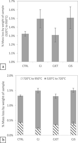
The formation of CaCO3 can fill pores in meso and micro sizes which enhances the material's microstructure [Citation43]. The crystallinity of CaCO3 can be influenced by several factors, including the chemical composition of the cement, impurities, and additives [Citation44]. The crystallinity of CaCO3 can be categorised into poorly-crystalline 520°C–720°C and well-crystalline 720°C–950°C [Citation45, Citation42, Citation46]. The result aligns with existing literature, where poorly crystalline values were found to be higher than well-crystalline values [Citation45]. Poorly crystalline values are often found to be higher than well-crystalline values due to the nature of the crystallisation process. When CaCO3 forms in a cementitious matrix, it is usually in a disordered or amorphous state, which is poorly crystalline. Especially in the early stages of CaCO3 formation, the environmental conditions may favour the rapid nucleation and growth of poorly -crystalline forms. These forms are less stable and have higher reactivity compared to the more ordered, well-crystalline CaCO3. As a result, poorly-crystalline CaCO3 tend to be more abundant in certain conditions or environments.
As shown in and elaborated in Section 2.3 and 2.4, the CO2 was jetted into the top surface of the filament of the CP sample at close proximity, leading to increased CO2 sequestration efficiency. Among the samples, CJ and CJS exhibited the most promising results (See ). When comparing the CJ sample with the CTRL sample, there is a 15% increase in carbon uptake. Further enhancement in capture efficiency could be achieved by elevating the CO2 concentration or prolonging the exposure duration [Citation40]. From , all samples printed with a carbon jetting show larger variance when compared to the control samples. One potential factor contributing to this variation could be the sampling technique, as shown in . Alternative approaches such as obtaining a complete cross-section slice and employing a pulverisation method can potentially improve the consistency of results. It's worth mentioning that while efforts to reduce this variance can enhance experimental precision, it do not change the principles of the results in this study.
It should be emphasised that, in contrast to conventional carbon sequestration and capture techniques, the method proposed in this manuscript involves significantly shorter exposure durations and operates at much lower pressure. This may result in comparatively reduced carbon sequestration efficiency. However, this approach, when applied during printing has the potential to revolutionise carbon capture on a broader scale. It may be coupled with existing carbon sequestration technology to improve sequestration efficiency. Furthermore, through the use of this in-situ carbon sequestration, it can facilitate large-scale carbon sequestration that is not constrained by chamber size limitations.
The TGA result for samples produced under various printing parameters are shown in . Each sample was replicated three times, and the averages are presented to illustrate the overall trend observed across the three trials. These TGA and DTG results obtained are in good agreement with existing literature [Citation47–50]. In the TGA curves, all samples exhibit a sharp mass loss from the beginning of the experiment, corresponding to a derivative thermogravimetry (DTG) peak below 180°C. This can be attributed to the evaporation of structurally unbound water of ettringite and calcium silicate hydrate (C–S–H) [Citation47].
Figure 8. Thermogravimetric analysis (TGA) and derivative thermogravimetry (DTG) result of the samples with different printing parameters; (a) combined results for comparison between TGA and DTG; (b) Thermogravimetric analysis (TGA) result; (c) derivative thermogravimetry (DTG) result; (d) zoomed in derivative thermogravimetry (DTG) result for temperature between 520°C and 950°C.
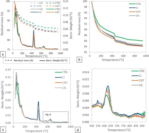
The next DTG peak occurs between 400°C and 450°C, which is associated with the dehydroxylation of portlandite [Citation49]. As seen in (b and d), samples exposed to CO2 demonstrate a much steeper decline in residual mass as temperature increase and exhibit higher DTG values compared to the control sample. This phenomenon may be associated with the presence of carbonation. The surface exposed to CO2 may lead to an extensive network of CaCO3 formations in the concrete microstructure on the surface which can cause a reduction in pore size and permeability [Citation51]. This could potentially lead to increased water retention within the material, contributing to the higher weight loss during the evaporation phase. It is evident that a significant amount of Ca(OH)2 remains unreacted with CO2 and has not fully transformed to CaCO3. The addition of CO2 jetting could have carbonated a protective layer of CaCO3 encapsulating the unreacted Ca(OH)2 particles [Citation52].
CaCO3 decomposes in the temperature range between 520°C and 950°C yielding CaO and CO2 [Citation46]. As seen in (d), all CO2 jetted sample exhibits a higher degree of weight loss, corresponding to higher amount of CaCO3 decomposition [Citation53]. Existing literature indicates that increasing the degree of carbonation in concrete requires prolonged exposure to CO2 with high concentrations [Citation54]. While the proposed method of printing does enhance carbon sequestration, prolonged duration with higher CO2 concentration will likely yield improved results.
3.2. Mechanical strength evaluation
The incorporation of various carbon jetting methods with 3DCP was observed to have a negative effect on its flexural strength and compressive strength performance (See and ). A possible explanation would be the decline effect that integrating carbon dioxide with 3DCP has on the compaction of printed concrete samples, particularly along its cross-sections. This is attributed to the purging effect it has on concrete filaments during 3DCP, as the fixed direction of pressurised CO2 jetting would counteract with printing paths for about 50% of its total travelling trajectory. As mentioned earlier, this would lead to undesired material losses during its print process, causing better mixing, as well as large cavities and gaps to form along the horizontal directions, particularly at the layer interfaces. The presence of large cavities and gaps along horizontal planes of samples would result in poorer interlayer bonding strengths and irregular density of its cross-section, consequently reducing its flexural performance. As the CO2 is being jetted onto the top surface of the filament, it may also lead to a drying effect on the filament’s surface. Previous studies have indicated that losing moisture can negatively impact how well layers adhere together, potentially affecting strength and plastic shrinkage [Citation55, Citation56]. Moreover, there can be internal stress within the layers of 3D printed structures when there is a slight change in moisture content [Citation57]. Further research on the moisture levels of the filament's surface can be conducted to better understand these effects, as it is not the primary focus of this study.
Figure 9. Flexural strength of control samples, CO2 jetting (CJ) sample, CO2 jetting at elevated temperature (CJET) samples and CO2 with steam printing (CJS) samples.
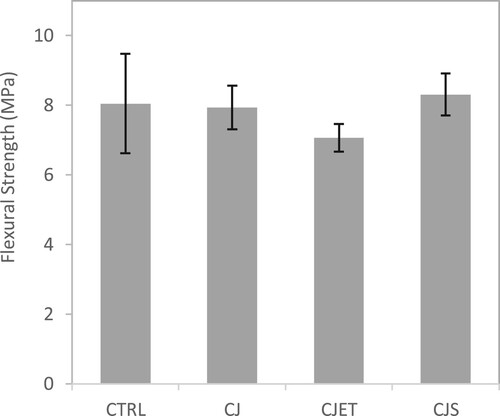
Figure 10. Compressive strength of control samples, CO2 jetting (CJ) sample, CO2 jetting at elevated temperature (CJET) samples and CO2 with steam printing (CJS) samples.
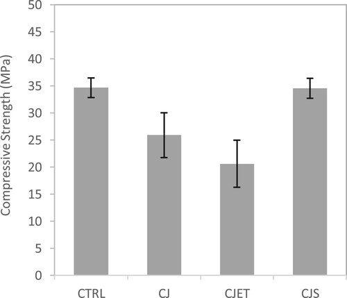
While the retention of water is observed in , it doesn't appear to significantly enhance the hardened properties of the filament. This could suggest that although water retention occurs, it may not directly translate to improve strength gain. In fact, the reduction in pore size may have more detrimental impact on the interlayer bonding strength. It's plausible that the surface pore size reduces due to carbonation, the altered microstructure may influence the adhesive properties between adjacent layers. This phenomenon merits further investigation to elucidate its implications for overall material performance and structural stability in 3D-printed objects. Both and show similar behaviour. The CJ and CJET samples were found to have lower mechanical strength than the control samples. Whereas for the CJS sample, it has a higher mechanical strength than both the CJ and CJET samples. For the CJS method sample, the purging effect is much stronger due to the combination of both the flow from the steam and the CO2 this could have caused better mixing of the material extruded and the layer below, thus resulting in better overall strength when comparing to the other carbon jetting methods.
4. Conclusion
The production of concrete and its primary binding agent OPC is responsible for a significant amount of greenhouse gas emissions and energy consumption. As the global concentration of CO2 continues to rise, there is a pressing need for sustainable alternatives in the construction sector. The development of 3DCP has gained interest as a more efficient and sustainable construction method. However, there is still room for reducing the carbon footprint of 3DCP. Integrating carbon capture and sequestration technologies directly into the 3DCP process presents a more complementary approach.
This study investigated the efficacy of in-situ carbon sequestration during 3D printing of cementitious materials using various carbon jetting methods. The results demonstrate that the interaction of CO2 with calcium silicates in cement showed promising results in promoting the precipitation of CaCO3 in the printed samples although poorly-crystalline forms were predominant. The printing approach and CO2 jetting configuration influenced the carbon uptake, particularly CJ and CJS, exhibited promising results in terms of carbon sequestration efficiency, with a 15% increase observed in the CJ sample compared to the control. The exposure to CO2 led to significant changes in mass loss for the TGA result, indicating the influence of carbonation on the concrete microstructure. Notably, a protective layer of CaCO3 encapsulating unreacted Ca(OH)2 particles was observed.
In terms of mechanical strength, the incorporation of carbon jetting methods may have affected negatively which may be attributed to the purging effect of pressurised CO2, potentially leading to material losses and reduced interlayer bonding strength. This resulted in the formation of large cavities, gaps, and irregular density along the horizontal planes, leading to poorer interlayer bonding strengths and reduced flexural performance. The results also suggested that while water retention occurred, it did not directly translate to improved strength gain, and the altered microstructure may influence interlayer bonding.
In conclusion, while the integration of CO2 with 3DCP has the potential for carbon sequestration, improvements are needed to address the limitations observed in mechanical strength performance. Further research and development are necessary to optimise the printing approach, CO2 jetting configurations, and curing conditions to achieve a more balanced and efficient integration of carbon capture and sequestration technologies with 3DCP. This study serves as a preliminary exploration of this topic and encourages future academic and practical investigations in this field. The method can be complementary to existing sequestration technologies, facilitating large-scale carbon sequestration without chamber size limitations. By advancing the understanding and implementation of sustainable practices in the building and construction industry, we can contribute to mitigating the environmental impact of construction activities and move towards a more sustainable and climate-resilient future.
Credit authorship contribution statement
Tay Yi Wei Daniel and Phua Seng Liang Bryan: Writing original-draft, conceptualisation Methodology and Data curation. Lim Sean Gip: Writing – review & editing. Tan Ming Jen, Bandar Fadhel and Issam Amr: Writing – review & editing, Resources and Supervision.
Disclosure statement
No potential conflict of interest was reported by the author(s).
Data availability statement
The authors confirm that the data supporting the findings of this study are available within the article.
Additional information
Funding
References
- Le Quéré C, Jackson R, Jones M, et al. Temporary reduction in daily global CO2 emissions during the COVID-19 forced confinement. Nat Clim Change. 2020;10:647–653. doi:10.1038/s41558-020-0797-x
- Sandeep BGB. Reduction of greenhouse gas emission by carbon trapping concrete using carboncure technology. Appl J Environ Eng Sci. 2021;7(3):7–317. doi:10.48422/IMIST.PRSM/ajees-v7i3.28111
- Linden LZ. (2017). “Energy analysis for producing low carbon-footprint cementitious building material,” [Online]. https://escholarship.org/uc/item/5g4321ch#main.
- Nocito F, Dibenedetto A. Atmospheric CO2 mitigation technologies: carbon capture utilization and storage. Curr Opin Green Sustain Chem. 2020;21:34–43. doi:10.1016/j.cogsc.2019.10.002
- Zhang S, DePaolo DJ. Rates of CO2 Mineralization in geological carbon storage. Acc Chem Res. Sep 2017;50(9):2075–2084. doi:10.1021/acs.accounts.7b00334
- National Academies of Sciences, Engineering, and Medicine; Division on Earth and Life Studies; Ocean Studies Board; Board on Chemical Sciences and Technology; Board on Earth Sciences and Resources; Board on Agriculture and Natural Resources; Board on Energy and Environmental Systems; Board on Atmospheric Sciences and Climate; Committee on Developing a Research Agenda for Carbon Dioxide Removal and Reliable Sequestration. 2018. Negative Emissions Technologies and Reliable Sequestration: A Research Agenda. The National Academies Press (US). doi:https://doi.org/10.17226/25259
- Bobeck J, Peace J, Ahmad FM, et al. (2019). “Carbon utilization: a vital and effective pathway for decarbonization,” [Online]. Available: https://www.c2es.org/document/carbon-utilization-a-vital-and-effective-pathway-for-decarbonization/.
- Hills CD, Tripathi N, Carey PJ. Mineralization technology for carbon capture, utilization, and storage. Front Energy Res. 2020;8; doi:10.3389/fenrg.2020.00142
- Galan I, Andrade C, Mora P, et al. Sequestration of CO2 by concrete carbonation. Environ Sci Technol. Apr. 201;44(8):3181–3186. doi:10.1021/es903581d
- Cui H, Tang W, Liu W, et al. Experimental study on effects of CO2 concentrations on concrete carbonation and diffusion mechanisms. Constr Build Mater. 2015;93:522–527. doi:10.1016/j.conbuildmat.2015.06.007
- Ekolu SO. A review on effects of curing, sheltering, and CO2 concentration upon natural carbonation of concrete. Constr Build Mater. 2016;127:306–320. doi:10.1016/j.conbuildmat.2016.09.056
- Talakokula V, Bhalla S, Ball RJ, et al. Diagnosis of carbonation induced corrosion initiation and progression in reinforced concrete structures using piezo-impedance transducers. Sens Actuators, A Phys. 2016;242:79–91. doi:10.1016/j.sna.2016.02.033
- Diasa RL, Beltrame NAM, Gonzalez JR, et al. Effect of duration and pressure of carbonation curing on the chloride profile in concrete. IBRACON Struct Mater J. 2023;16(5):e16603, doi:10.1590/S1983-41952023000600003
- Zhang D, Shao Y. Effect of early carbonation curing on chloride penetration and weathering carbonation in concrete. Constr Build Mater. 2016;123:516–526. doi:10.1016/j.conbuildmat.2016.07.041
- Tay YWD, Lim JH, Li M, et al. Creating functionally graded concrete materials with varying 3D printing parameters. Virtual Phys Prototyp. 2022;17(3):662–681. doi:10.1080/17452759.2022.2048521
- Nguyen PD, Nguyen TQ, Tao QB, et al. A data-driven machine learning approach for the 3D printing process optimisation. Virtual Phys Prototyp. 2022;17(4):768–786. doi:10.1080/17452759.2022.2068446
- Shojaei Barjuei E, Courteille E, Rangeard D, et al. Real-time vision-based control of industrial manipulators for layer-width setting in concrete 3D printing applications. Adv Ind Manuf Eng. 2022;5:100094, doi:10.1016/j.aime.2022.100094
- Panda B, Paul SC, Hui LJ, et al. Additive manufacturing of geopolymer for sustainable built environment. J Cleaner Prod. 2017;167:281–288. doi:10.1016/j.jclepro.2017.08.165
- Amran YHM, Alyousef R, Alabduljabbar H, et al. Clean production and properties of geopolymer concrete: a review. J Cleaner Prod. 2020;251:119679, doi:10.1016/j.jclepro.2019.119679
- van Zijl G, Babafemi AJ, de Villiers W, Kruger J. 3D concrete printing opportunities towards circularity – mix design, testing and mechanical performance. 2023. Available at SSRN: https://doi.org/10.2139/ssrn.4481392 (accessed Oct. 04, 2023).
- Bhattacherjee S, Jain S, Santhanam M. Developing 3D printable and buildable limestone calcined clay-based cement composites with higher aggregate content. Constr Build Mater. 2023;376:131058, doi:10.1016/j.conbuildmat.2023.131058
- Dey D, Srinivas D, Panda B, et al. Use of industrial waste materials for 3D printing of sustainable concrete: a review. J Cleaner Prod. 2022;340:130749, doi:10.1016/j.jclepro.2022.130749
- Wang D, Xiao J, Sun B, et al. Mechanical properties of 3D printed mortar cured by CO2. Cem Concr Compos. 2023;139:105009, doi:10.1016/j.cemconcomp.2023.105009
- Sun B, Zeng Q, Wang D, et al. Sustainable 3D printed mortar with CO2 pretreated recycled fine aggregates. Cem Concr Compos. 2022;134:104800, doi:10.1016/j.cemconcomp.2022.104800
- Dixit A, Du H, Pang SD. Carbon capture in ultra-high performance concrete using pressurized CO2 curing. Constr Build Mater. 2021;288:123076, doi:10.1016/j.conbuildmat.2021.123076
- Monkman S, MacDonald M, Hooton RD, et al. Properties and durability of concrete produced using CO2 as an accelerating admixture. Cem Concr Compos. 2016;74:218–224. doi:10.1016/j.cemconcomp.2016.10.007
- He Z, Li Z, Shao Y. Effect of carbonation mixing on CO2 uptake and strength gain in concrete. J Mater Civ Eng. 2017;29(10):04017176, doi:10.1061/(ASCE)MT.1943-5533.0002031
- Qian X, Wang J, Fang Y, et al. Carbon dioxide as an admixture for better performance of OPC-based concrete. J CO2 Util. 2018;25:31–38. doi:10.1016/j.jcou.2018.03.007
- Kong Y, Song Y, Weng Y, et al. Influences of CO2-cured cement powders on hydration of cement paste. Greenh Gases: Sci Technol. 2022;12(2):249–262. doi:10.1002/ghg.2141
- Ravikumar D, Zhang D, Keoleian G, et al. Carbon dioxide utilization in concrete curing or mixing might not produce a net climate benefit. Nat Commun. 2021;12(1):855, doi:10.1038/s41467-021-21148-w
- Tay YWD, Panda B, Ting GHA, et al. 3D printing for sustainable construction). Industry 4.0 - Shaping the Future of the Digital World: Proceedings of the 2nd International Conference on Sustainable Smart Manufacturing (S2m 2019), 2020, p. 119–123, doi:10.1201/9780367823085-22
- Kruger J, du Plessis A, van Zijl G. An investigation into the porosity of extrusion-based 3D printed concrete. Addit Manuf. 2021;37:101740, doi:10.1016/j.addma.2020.101740
- A. O. Al-Khowaiter, A. Jamal, I. T. Amr, R. Bamagain, A. S. Al-Hunaidy, and B. A. Fadhel, “Cementitious Print Head, 3D Printing Architecture, and Cementitious Printing Methodology,” Patent No: US11236517 B2, 2022.
- Tay YWD, Li MY, Tan MJ. Effect of printing parameters in 3D concrete printing: printing region and support structures. J Mater Process Technol. 2019;271:261–270. doi:10.1016/j.jmatprotec.2019.04.007
- Wang D, Noguchi T, Nozaki T. Increasing efficiency of carbon dioxide sequestration through high temperature carbonation of cement-based materials. J Cleaner Prod. 2019;238:117980, doi:10.1016/j.jclepro.2019.117980
- Kim S, Amr IT, Fadhel BA, et al. The effect of combined carbonation and steam curing on the microstructural evolution and mechanical properties of Portland cement concrete. Adv Concr Constr. 2021;11(5):367, doi:10.12989/acc.2021.11.5.367
- ASTM C109 / C109M-21. Standard test method for compressive strength of hydraulic cement mortars (using 2-in. or [50-mm] cube specimens). West Conshohocken (PA): ASTM International; 2021.
- Kim MS, Jun Y, Lee C, et al. Use of CaO as an activator for producing a price-competitive non-cement structural binder using ground granulated blast furnace slag. Cem Concr Res. 2013;54:208–214. doi:10.1016/j.cemconres.2013.09.011
- Madadi A, Wei J. Characterization of calcium silicate hydrate gels with different calcium to silica ratios and polymer modifications. Gels (Basel, Switzerland). 2022;8(2):75. doi:10.3390/gels8020075
- Haghnegahdar MR, Rahimi A, Hatamipour MS. A rate equation for Ca(OH)2 and CO2 reaction in a spouted bed reactor at low gas concentrations. Chem Eng Res Des. 2011;89(6):616–620. doi:10.1016/j.cherd.2010.10.019
- Villain G, Thiery M, Platret G. Measurement methods of carbonation profiles in concrete: thermogravimetry, chemical analysis and gammadensimetry. Cem Concr Res. 2007;37(8):1182–1192. doi:10.1016/j.cemconres.2007.04.015
- Rostami V, Shao Y, Boyd AJ, et al. Microstructure of cement paste subject to early carbonation curing. Cem Concr Res. 2012;42(1):186–193. doi:10.1016/j.cemconres.2011.09.010
- Mehdizadeh H, Meng Y, Guo M-Z, et al. Roles of CO2 curing induced calcium carbonates on high temperature properties of dry-mixed cement paste. Constr Build Mater. 2021;289:123193, doi:10.1016/j.conbuildmat.2021.123193
- Chang R, Kim S, Lee S, et al. Calcium carbonate precipitation for CO2 storage and utilization: a review of the carbonate crystallization and polymorphism. Front Energy Res. 2017;5; doi:10.3389/fenrg.2017.00017
- Tu Z, Guo M, Poon CS, et al. Effects of limestone powder on CaCO3 precipitation in CO2 cured cement pastes. Cem Concr Compos. 2016;72:9–16. doi:10.1016/j.cemconcomp.2016.05.019
- Vogler N, Drabetzki P, Lindemann M, et al. Description of the concrete carbonation process with adjusted depth-resolved thermogravimetric analysis. J Therm Anal Calorim. 2022;147(11):6167–6180. doi:10.1007/s10973-021-10966-1
- Seo J, Park S, Yoon HN, et al. Effect of CaO incorporation on the microstructure and autogenous shrinkage of ternary blend Portland cement-slag-silica fume. Constr Build Mater. 2020;249:118691, doi:10.1016/j.conbuildmat.2020.118691
- Seo JH, Park SM, Lee HK. Evolution of the binder gel in carbonation-cured Portland cement in an acidic medium. Cem Concr Res. 2018;109:81–89. doi:10.1016/j.cemconres.2018.03.014
- Silva DA, Roman HR, Gleize PJP. Evidences of chemical interaction between EVA and hydrating Portland cement. Cem Concr Res. 2002;32(9):1383–1390. doi:10.1016/S0008-8846(02)00805-0
- Collier NC. Transition and decomposition temperatures of cement phases – a collection of thermal analysis data. Ceram-Silik. 2016;60(4):338–343. doi:10.13168/cs.2016.0050
- Winnefeld F, Leemann A, German A, et al. CO2 storage in cement and concrete by mineral carbonation. Curr Opin Green Sustain Chem. 2022;38:100672, doi:10.1016/j.cogsc.2022.100672
- Galan I, Glasser FP, Baza D, et al. Assessment of the protective effect of carbonation on portlandite crystals. Cem Concr Res. 2015;74:68–77. doi:10.1016/j.cemconres.2015.04.001
- Ashraf W, Olek J. Carbonation activated binders from pure calcium silicates: reaction kinetics and performance controlling factors. Cem Concr Compos. 2018;93:85–98. doi:10.1016/j.cemconcomp.2018.07.004
- Kazemian M, Shafei B. Carbon sequestration and storage in concrete: a state-of-the-art review of compositions, methods, and developments. J CO2 Util. 2023;70:102443, doi:10.1016/j.jcou.2023.102443
- Moelich GM, Kruger J, Combrinck R. Modelling the interlayer bond strength of 3D printed concrete with surface moisture. Cem Concr Res. 2021;150:106559, doi:10.1016/j.cemconres.2021.106559
- Moelich GM, Kruger J, Combrinck R. Plastic shrinkage cracking in 3D printed concrete. Compos Part B: Eng. 2020;200:108313, doi:10.1016/j.compositesb.2020.108313
- Slavcheva GS. Drying and shrinkage of cement paste for 3D printable concrete. IOP Conf Ser: Mater Sci Eng. 2019;481(1):012043, doi:10.1088/1757-899X/481/1/012043