
 ?Mathematical formulae have been encoded as MathML and are displayed in this HTML version using MathJax in order to improve their display. Uncheck the box to turn MathJax off. This feature requires Javascript. Click on a formula to zoom.
ABSTRACT
Material extrusion additive manufacturing is of increased interest in producing materials with very high loadings of particles, specifically through the use of the direct ink write (DIW), or robocasting, technique and the use of highly loaded particle suspensions (HLS). Applications from biomedical composites to solid rocket propellants to powder metallurgy green bodies would benefit from the complex parts enabled by additive manufacturing but require very high particle contents during processing. This leads to very high viscosity fluids and challenges in flowing and curing the inks. In this comprehensive review, we examine the main components of designing an ink formulation and a DIW process: the ink rheology, the print mechanics and the solidification/post-processing. Our expanded discussion of these elements includes an introduction to the basics as well as the latest research in the field, so serves to both introduce a new practitioner and generate new ideas for those already working in the area. We finish with a discussion of two important applications and a perspective on the future directions of DIW for highly loaded particle materials.
GRAPHICAL ABSTRACT

1. Introduction
Materials comprised of highly loaded particle suspensions (HLS) play an important role in a range of industries. Examples of HLS include solid rocket motor propellant, bone scaffolding composites for tissue regeneration, chocolate, powder metallurgy green bodies and ceramic green bodies [Citation1–4]. These suspensions are a composite of low aspect-ratio particles suspended in a matrix, often a polymeric binder and are used when it is advantageous to increase particle content in order to maximise the influence of a desired particle property on the composite property, be it energy, bioactivity, or minimisation of shrinkage on post processing [Citation5]. Minimisation of binder material, without compromising composite cohesion and strength, can help ensure desired particle properties are mirrored in the overall bulk composite [Citation6]. A suspension will have different mechanical and rheological properties when the maximum particle loading is reached compared to a dilute case [Citation7]. This maximum loading for a flowable suspension depends on teh aspect ratio of the particles, among other factors [Citation7,Citation8], and as such, there is no single definition for highly loaded and it depends on the type of particles used. For equiaxed, low-aspect ratio particles, high solids loadings are usually in the range of 50–60% by volume [Citation9,Citation10], while for platelet particles with a different packing mechanism, high solid loadings can be met at 15–25% by volume [Citation11,Citation12]. In this review, our focus is centred on low-aspect ratio particles. Therefore, to maintain consistency between different studies discussed, a particle loading of >55% by volume is implied when referring to HLS materials unless otherwise noted.
While the range of additive manufacturing techniques is wide, this review focuses on material extrusion additive manufacturing, which we further segment down to direct ink write (DIW). We refer readers to the comprehensive work by Small et al. for a broader discussion of other techniques [Citation13]. DIW is an emerging AM technique for HLS that has been utilised for a growing number of applications [Citation14–16]. It uses pressure to deposit a continuous filament of material, typically without the aid of heat or vibration in the deposition process. DIW with HLS continues to receive attention from both academia and industry. Companies such as Dimension Inx, ICON and Desktop Metal employ a variety of methods to print particle suspensions using a mixture of heat and pressure or solely pressure to extrude their materials [Citation17–19]. Dimension Inx, for instance, has generalised its services to include ceramic-polymer HLS and focuses on supplying customised inks and products rather than developing an end-to-end user system, which requires companies to develop printing expertise [Citation17,Citation18]. These companies represent a small cross section of the burgeoning start-up industry evolving around printing HLS using a variety of extrusion-based AM techniques.
The commercial appeal of DIW for 3D printing can in part originate from the large degrees of freedom in formulation design. The flexibility in ink or feedstock allows DIW to be used for tailored suspensions for a wide range of materials and applications, as different solidification techniques can be exploited to accommodate needs of the particle material and binder. For example, in contrast with fused filament fabrication (FFF), where a solid filament is melted and extruded to deposit material layer by layer, DIW typically utilises flowable particle suspensions with reported viscosities ranging from 9800–500,000 cP [Citation20,Citation21]. Where stereolithography (SLA) and digital light processing (DLP) 3D printing also have demonstrated uses with high contents of solid particles [Citation22], DIW brings in more possible solidification mechanisms, which can allow for higher content of particles. This review addresses these solidification mechanisms and the effect of high contents of particles on solidification.
The goal of this review is to provide a comprehensive view of the important fundamental aspects of designing inks and processes for manufacturability by presenting an analysis of literature on material extrusion additive manufacturing, in particular DIW, of HLS . Rather than attempting to give a detailed review of all printed HLS materials and applications, we choose to focus on generalised processing strategies that are important to the success of the HLS materials class. Importantly, we examine the rheology/ink design for flowability and shape retention, the printing processing parameters, and the part solidification and post-processing. Examples highlighting the role of HLS in propellent processing and bone scaffold engineering are discussed in Section 5.0 of this review to demonstrate how AM approaches might contribute to enhanced performance, but examples are not meant to be comprehensive. The applications discussed illustrate situations where successful outcomes require both highly loaded particle content and precise geometrical or compositional control [Citation23]. These examples link discussions in other sections to real-world applications.
Understanding the interplay between suspension properties, such as composition, particle size and particle loading in HLS materials, and the unique physical environments present during DIW processing will be key to advancing and further commercialising this technology across all industries. While the significant particle-particle interactions due to high particle density in HLS materials make printing more difficult to understand than printing suspensions with a lower particle content, it is still possible to draw on lessons learned from more mature printing techniques and formulations to predict HLS behaviour and estimate physical models [Citation22]. There is a broad range of applications for HLS DIW, and factors such as particle size, particle size distribution, chosen binder, presence of surfactants (if any), and external print aids such as vibration or heat are all design parameters that effect final part properties. In analysing the existing literature for this review, we will explore underlying physical principles that contribute to observed outcomes at each stage of HLS DIW processing and post processing. Additionally, limitations that need to be addressed before widespread adoption of this technique is possible will be discussed.
2. Rheology and ink formulation
Frequently HLS materials are designed for printability by controlling the rheology of the mixture, a feature that has been exploited to maximise the solids loading of many different materials [Citation14,Citation24]. Good rheological characterisation of a DIW ink is the foundation for understanding the changes occurring at the macro and microstructural levels during printing. At the macroscale, the material should extrude continuously, deposit onto a substrate or itself and retain a rod-like shape capable of withstanding the weight of additional printed layers. At the microscale, the particle distribution and binder solidification are important parameters dictating the success of a print. Contrary to dilute suspensions, where the solid loading is low and where the binder properties dominate fluid behaviour, particle-particle interactions have a much greater impact at solid loadings above 30 vol% [Citation25,Citation26]. Closer to the maximum packing fraction for smooth monomodal spheres, above 60 vol%, these effects are dominant [Citation27]. As a result, the material properties become much more complex for HLS, and significant deviations from conventional processing results are expected when solid loadings surpass 55 vol%. As this review is geared towards a broad audience, we start each section with an introduction to key rheological concepts for DIW and then discuss how the ink properties and use of HLS impact those rheological properties in the context of material extrusion additive manufacturing. summarises key rheological parameters for select publications referred to in this chapter.
Table 1. Select HLS studies and the relevant rheological parameters. k and n are the power law constants in Equation (3), PDMS is polydimethylsiloxane, PVP is polyvinyl pyrrolidone, NZF is NiZn-ferrite, SIS is polystyrene-polyisoprene-polystyrene, NMP is N-Methyl-2-pyrrolidone, PZT is lead zirconate titanate, PEI is polyethyleneimine
2.1. Viscosity
The shear viscosity of an ink is a measure of shear deformation in the material in response to an applied stress. This deformation in shear flow is measured as the material strain and can depend on time, which is referred to as strain rate, or shear rate. The stress is simply a force applied over a specific area of the material. Together, the shear stress, and the shear rate,
provide the well-known relationship for dynamic viscosity,
:
(1)
(1) The viscosity response to shear rate is used to classify the ink either as Newtonian, shear-thinning, or shear-thickening. For a Newtonian fluid, such as water, viscosity is linearly dependent on shear rate or shear stress, but in shear-thinning and shear-thickening materials, viscosity will decrease and increase, respectively, with increasing applied shear, as illustrated in . While viscous fluids that exhibit all three types of behaviours can be additively manufactured through DIW [Citation28,Citation36,Citation37], all require some shear-thinning behaviour to be extrudable through the nozzle. In DIW, shear-thinning materials are favourable as they facilitate extrusion by reducing the likelihood of clogging the nozzle.
Figure 1. Illustration of material behaviour upon imposed shear. The dashed green line shows Newtonian characteristics, the solid purple curve represents shear thinning and the dotted blue curve represents shear thickening.
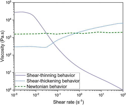
A recommended range of ink viscosity for DIW applications is 0.1–103 Pa•s [Citation38]. With a shear thinning material, even highly viscous pastes can be extruded, provided they exhibit sufficient shear-thinning behaviour. Acosta et al. report on the flow properties of highly loaded colloidal suspensions of alumina (55.7 vol%), with a viscosity on the order of 102 Pa•s reduced by two orders of magnitude when subjected to shear rates of 100 s−1 and above [Citation39]. Sweeney et al. analysed suspensions of 80 wt% solids (approximately 73 vol%) with varying particle sizes, and presented even greater viscosity reductions, of up to five orders of magnitude for shear rates ramped from 0.01 to 10 s−1. However, due to the high initial viscosities of the suspensions (104–106 Pa•s) and printing equipment limits, the relatively high pressure required to extrude these pastes is impractical. Instead, the initial viscosity can be lowered by preshearing the suspensions, creating a particle network more favourable to flow and lowering the pressure requirements [Citation27].
By carefully mapping the viscosity of a material over a range of printing shear rates, insights into the material response during processing can be obtained. Notably, the viscosity of the suspension at the highest shear rate during extrusion in the DIW nozzle can be determined. Because shear-thinning materials experience a reduction in viscosity during extrusion, the curvature of the velocity profile for the material in the DIW nozzle is not finite at the nozzle wall. This phenomenon, known as wall slip, causes the highest observable shear rate of the suspension to occur at the wall and can be defined as a function of the volumetric flow rate of material out of the nozzle [Citation37].
(2)
(2) where
is the volumetric flow rate of the suspension and
is the radius of the nozzle. With the wall shear rate, the largest drop in viscosity during extrusion can be determined.
For a more fundamental perspective of the viscosity profile at a range of shear rates, rather than at a specific point, several mathematical models exist to describe shear-thinning and shear-thickening fluids. A simple approach includes the power law model:
(3)
(3) where the constants
and
represent the flow consistency and the flow index, respectively. This model serves to describe the type of flow for a fluid, with
indicating shear-thickening,
indicating shear-thinning and
indicating Newtonian behaviour. While good accuracy is obtained for the mid-range of shear rates, the power law model has drawbacks at very low and very high shear rates [Citation40]. Schwarze et al. investigated the rheological behaviour of weakly wetted particles (approximately 96 vol% solids), as well as that of dry sand for which the power law failed to fit their experimental data. Instead, three different regimes at low, medium and high shear rates were identified, each with different flow indexes. Interestingly, this phenomenon disappeared upon addition of a liquid binder. By instead considering particle-particle interactions and taking the ratio of the relaxation time to the shear time, also known as the dimensionless inertial number I, the power law fits both dry and wet samples, regardless of shear rate range [Citation41].
For more complex materials, such as HLS, where both the binder and the solids contribute to flow mechanics, the Herschel–Bulkley model is often a more robust model to use. These materials, whose behaviours exhibit both fluid and solid-like properties and are termed viscoelastic, yield before flowing (further discussion on yield point/stress is provided in the following section). Classically, the Bingham plastic model is used to describe such yielding fluids, and the Herschel–Bulkley model serves as an extension to the Bingham plastic model by bridging it to the power law model with a shear rate dependence [Citation42]. The Herschel–Bulkley model is written as follows:
(4)
(4) Here,
and
still represent the consistency and the flow index, and
represents the yield stress of the material. Acosta et al. noted that below 30 vol% alumina particles in aqueous polyvinylpyrrolidone, the suspensions tend to behave as Newtonian fluids, but that with increasing particle loading the suspension becomes increasingly shear-thinning and yielding up to the highest particle loading studied (55.7 vol%). The rheological behaviour of the suspensions under varying shear rates was very well represented by the Herschel–Bulkley model [Citation39]. When comparing the flow curves of concentrated emulsions between surfaces of different roughness and hydrophobicity, Malkin et al. noted that the Herschel–Bulkley model best fit flow between two rough surfaces and failed at low shear rates for smooth surfaces. The authors attributed the difference to the presence of wall slip in the smooth surfaces, which caused the shear rate to be overestimated [Citation43]. This demonstrates that it is necessary to remove, or account for, potential artefacts (i.e. wall slip) that may skew measurements in these complex fluids. For a parallel plate rheometer, wall slip can be minimised by increasing the surface roughness of the plates in contact with the sample, through the use of sandpaper covered or cross-hatched plate surfaces.
2.2. Yield stress
A material is yielding if it experiences a rapid decrease in viscosity at low shear rates. In DIW, this corresponds to the force required to begin flowing. If too little force is exerted, the material will deform elastically and will not flow. A useful characterisation method for this is to use rheology to quantify the stress at which the material yields. This can be accomplished through a measure of the shear stress in a shear rate sweep experiment and fit the data to non-linear models such as the Herschel–Bulkley model. Yielding materials will have a non-zero intercept on a shear stress vs. shear rate plot, and a viscosity peak on a viscosity vs. shear rate plot.
A low yield stress is recommended to facilitate flow through a nozzle and lower the equipment demands for extrusion. The minimum driving pressure that must be exerted on a piston in order to push the ink out of the nozzle tip is directly related to the ink's yield stress, [Citation27]:
(5)
(5) where
and
are the nozzle's length and diameter respectively, and
is the yield stress of the ink to be extruded. When large driving pressures are required, the yield stress can be reduced with a short preshear step, which could involve sonicating the ink prior to extrusion [Citation44,Citation45].
The importance of a material's yield stress is not only limited to the start of flow. In fact, the yield stress also contributes to shape retention after layer deposition. To differentiate between the yield stress required to extrude and that required to maintain and build a three-dimensional structure, M’Barki et al. proposed a static yield stress and a dynamic yield stress. These can be determined by subjecting the material to a shear rate loop, first increasing the shear rate and then immediately ramping the shear rate back to a very low value, all the while measuring the stress response. The static yield stress is then interpreted at the onset sharp rise of the stress-shear rate slope in the initial increasing shear rate step and the dynamic yield stress is determined from the intercept for a Herschel–Bulkley fit at the shear rate ramp down step [Citation37].
A high dynamic yield stress is favourable for shape retention, as it implies that more force is required for the material to keep deforming. Rosental et al. demonstrated that for inks composed of barium titanate (BTO) particles, only those with dynamic yield stresses that equalled or surpassed 72 Pa were able to sustain the shape of the printed part, which corresponds to solid loadings of 75 wt% (approximately 13 vol%) BTO particles or greater. The authors also observed that the yield stress of the suspensions could be increased post-extrusion by facilitating solvent evaporation through the use of a heated bed [Citation46]. For acrylate-type hydrogels, Smith et al. showed that the materials better retained the filament shape and diameter post-extrusion if they had a higher dynamic yield stress, close to 300 Pa [Citation47].
For most materials, the static yield stress will be greater than the dynamic yield stress. Since recommendations suggest that a low static yield stress and a high dynamic yield stress are desired for printing, this poses a challenge in ink design and printing optimisation. In the processing decision matrix, the tradeoff is therefore between keeping equipment demands low, and achieving high print fidelity. Specific ink formulations that enable rapid solidification, such as solvent evaporation or UV curing of the ink post-extrusion can help optimise the yield stresses but must be carefully studied as these additives will also alter the ink's other rheological properties.
2.3. Modulus
A material's yield point also denotes an important phenomenon in its viscoelastic properties. Prior to yielding, the ink will behave elastically, as a solid. After yielding, the ink will flow like a liquid and behave viscously. This nature of the ink can be tracked with respect to deformation through its modulus. Unlike viscosity, the modulus directly relates the material stress to the material strain, and can be expressed as:
(6)
(6) where
is the maximum strain, or deformation of the material,
is the maximum applied stress to reach that deformation, and
is the complex modulus, a direct measure of the material's stiffness [Citation48]. The complex modulus is composed of both an elastic contribution, represented by
, and a viscous contribution denoted by
. Viscoelastic materials such as HLS inks exhibit both contributions, with
typically larger than
for small deformations. When shear-thinning, or during extrusion,
and
will decrease and increase, respectively, with increasing strain %, until a crossover point is reached, beyond which the magnitude of
dominates that of
[Citation29,Citation38]. At this stage, the ink behaves like a liquid and can be easily pushed out of the nozzle.
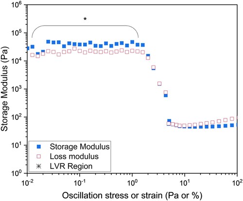
Since both strain and time affect a material's viscosity and modulus, it can be helpful to deconvolute each variable's effects on the material properties. To do so, the effect of strain is typically evaluated first, at a fixed frequency of 1 Hz or 10 rad/s to identify the linear viscoelastic regime (LVR), or the region where the material properties are independent of structure deformation [Citation30]. This phase can also be representative of an ink at rest in the printing syringe or on a printing substrate. shows a typical plot when determining the LVR, shown here for a 61.4 vol% bimodal glass microsphere suspension in a polyvinyl pyrrolidone (PVP)-water binder. The linear viscoelastic region is shorter for materials that exhibit more solid-like behaviour and longer for materials that are more fluid, likely due to the increased mobility of molecules in the liquid state and their ability to withstand more deformation before the material structure is destroyed [Citation49]. For HLS, the LVR is often short and can be difficult to identify.
Figure 2. Visual representation of the linear viscoelastic region (LVR) where material deformation is independent of stress or strain. Data from a 61.4 vol% bimodal glass microsphere suspension in a polyvinyl pyrrolidone (PVP)-water binder.
With the linear viscoelastic region defined, subsequent experiments to determine the dependence of the material's viscosity and modulus on time can be run within that region. These tests are typically performed as frequency sweeps, where the complex modulus, the storage and loss moduli, and even the complex viscosity can be measured as functions of increasing frequency. Sweeney et al. demonstrated for approximately 73.4 vol% pentaerythritol (PET) particles in a polydimethylsiloxane (PDMS) binder that, although a slight dependence on frequency could be observed, the materials behaved mostly quasi-statically, with larger than
[Citation27].
In addition to the frequency dependance of the storage and loss moduli, it is useful to study the transition between solid-like and liquid-like behaviour and the parameter is a useful for quantification. Defined as the ratio of
, a
indicates an elastic, solid-like behaviour while
indicates viscous, fluid-like behaviour. In a study comparing 61.4 vol% particle suspensions in binders prepared from UV curable monomers to those prepared from high molecular weight polymers dissolved in a solvent, Campbell et al. showed that the UV curable monomers had a
and this resulted in slumping after printing and prior to cure. The polymer/solvent formulations, on the other hand, had a
and did not display slumpting behavior [Citation31]. Sun et al. focused on understanding the drying process of printed suspensions using
and observed that an inversion point for
occurred after 4 h of drying for water, glass and kaolin clay suspensions (for 45 wt% or approximately 24.5 vol% of kaolin solids), indicating that the material had solidified [Citation50]. Designing for a rapid inversion of
ensures that an ink will not spread or deform significantly after extrusion, highlighting the value of analysing
in addition to more typical oscillatory time and frequency sweep rheology experiments.
In addition, quantifying the value of the storage modulus after the inversion point to , which corresponds to a solidified layer in the print, can help determine whether the print will be able to withstand multiple layers. Li et al. recommend a relaxation storage modulus exceeding 103 Pa to sustain two or more vertical printed layers, and a
smaller than 0.8 for successful solidification [Citation38]. However, if the material regains too high of an elasticity too quickly, adhesion between layers will be impaired, and fusing of two layers will be impossible, which can result in printed lines with additional porosity from trapped air between layers [Citation51]. While this is certainly suitable for space-spanning structures, such as print supports or hollow prints, it is undesirable for space-filling structures like solid prints. The material's time dependent rheological properties therefore need to be tuned carefully for the intended print purpose.
2.4. Thixotropy
The time dependent rheological properties of DIW inks are highly relevant following ink extrusion, when the shear-thinned suspension experiences little stress and is free to return to a stable, non-flowing state. When discussing this restructuring to a stable state, two potential phenomena arise, namely structural viscosity and thixotropy, with the difference between the two being the time required by the structure to regress to its initial state [Citation52]. The term structural viscosity is attributed to suspensions where the timescale for recovery from a deformation is so small that instruments are unlikely to record it. The material deformation and restructure are therefore only assumed to depend on applied stresses or strains, or in a general sense, the material is purely shear-thinning, shear-thickening, or Newtonian. When the timescale for restructuring is sufficiently long, in comparison to the data collection time, we can then say that a material is thixotropic if it exhibits shear thinning behaviour, and rheopectic if it exhibits shear-thickening behaviour. In DIW, contrary to other printing methods such as Fused Deposition Modelling (FDM), the timescale for ink solidification can be lengthy enough for the ink to display thixotropic behaviour.
Studying thixotropy through rheological techniques is therefore a good way to gain insights into a DIW ink's microstructure while mimicking the printing process. Thixotropy for HLS in the printing process begins with large aggregates in a random spatial distribution (for an ideal, well dispersed ink) at rest, the aggregate network then breaks apart into individual particles, which align in the direction of flow upon imposing pressure driven stress in the printer syringe [Citation52]. When this stress is removed, the particles redisperse to return to a lower energy state, flocculating once more into larger aggregates and a percolating network, as collisions occur. The rearrangement of the particles in the ink can impart reversible changes to the ink's viscosity, yield stress and modulus. However, full reversibility may not be accomplished if not enough time is given for the material to restructure, and the diffusion of particles with the binder is slow and impeded by limited interstitial space [Citation53]. This has consequences when printing subsequent layers, as an unstable base layer can cause a whole structure to collapse.
A simple approach to test whether a material is thixotropic is to run a hysteresis loop. Stress or viscosity changes are measured and recorded as the shear rate is linearly increased to a predetermined value and decreased back to the original shear rate. Typically, the observable behaviour is that upon ramping down of the shear rate, the stress or viscosity response lags behind due to the time needed for the material to rebuild its structure. As such, the ramp up and ramp down curves do not superpose, effectively creating a ‘loop’, as illustrated in A. The area between the two curves can be used to evaluate the magnitude of thixotropy as well as the energy required for the structure to break down [Citation54,Citation55]. Effectively, the larger the difference between the two curves, the more thixotropic a material is. Although useful as a preliminary analysis, a hysteresis loop cannot deconvolute the effects of shear rate and time on the suspension's viscoelastic response [Citation39,Citation52].
Figure 3. (A) Hysteresis loop showing a thixotropic material response for a PVP-methanol binder loaded with 61.4 vol% glass particles. (B) 3 interval thixotropy test (3ITT) for the same formulation. In the first interval, the structure is at rest at a low strain. In the second interval, a stress is applied to break up the network of particles. During the last interval, the same low strain is applied while the particles rearrange into a stable structure.
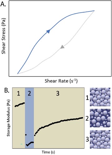
An alternative experiment for thixotropy involves oscillatory measurements of the storage modulus in what is known as a 3 Interval Thixotropy Test (3ITT) [Citation56,Citation57]. Operating in the oscillatory mode allows for careful characterisation, since the method is gentler than flow rheology, and can give valuable insights into highly loaded suspensions that are very susceptible to minor stresses. To begin a 3ITT in oscillatory rheology, the sample's LVR must be predetermined. Relying on knowledge of the sample's LVR is paramount, as 3ITT analyzes structure rebuilding following a period of deformation outside of the LVR. B shows the results of a typical 3ITT test for a PVP-methanol binder loaded with 61.4 vol% particles. The first interval consists of a given period of time during which the sample's storage modulus is measured at a strain value within the LVR. The sample is then deformed at a high strain value outside of the LVR in the second interval, during which the sample experiences a large drop in the storage modulus as the particle network structure is broken up. Lastly, in the third interval, the material is left to restructure at a low strain value within the LVR, where the elasticity typically increases and a steady-state value of may be reached.
As a comparison to DIW additive manufacturing, these intervals are analogous to the ink at rest in the syringe (step 1), pressure-driven extrusion of the ink through the syringe and nozzle (step 2), and relaxation of the ink onto the printing substrate following deposition (step 3). Thixotropy is evident in the last interval, during which the material recovery can be quantitively evaluated as a function of time:
(7)
(7) where
is the value of storage modulus at the beginning of the third interval,
is the steady-state modulus after recovery, and
is the time at the onset of the steady-state. If the sample loading history in the first interval is not significant, or if it was erased through preshear and relaxation steps, the difference between the storage modulus at the end of the first interval and
gives insight into the extent of reversible deformation of a sample's structure. Nan et al. observed structure recoveries up to 97.2% of the initial storage modulus for 35 wt% (approximately 17 vol%) glass particles suspended in a PluronicTM hydrogel, even after withstanding strains on the order of 500% [Citation56]. For DIW, a high degree of recovery is beneficial for the printed part to be structurally strong and to be able to build subsequent layers. In the same manner,
provides insight into the time needed for restructuring, which will vary with binder solidification mechanisms such as solvent evaporation, UV or thermal curing, and will serve as an indicator for printing pauses between layers.
Lastly, thixotropy can also be used to assess an ink's stability to step-wise increases in shear rates over a predetermined duration of time [Citation57,Citation58]. These experiments build on 3ITT tests, running from one steady-state to another, with ranges of structure deformation in the second interval increasing in shear rates throughout several cycles. In this fashion, Eom et al. investigated phase stability through a sequential map of the storage modulus and of 15–20 vol% Bi0.4Sb1.6Te3 (BST) particles (corresponding to 42–55 wt%) suspended in a chalcogenidometallate (ChaM) inorganic binder or glycerol in the range of 1–200 Pa. If the drop in
and increase in
occurs smoothly through a sequential increase in shear stress, the integrity of the phase stability is maintained, and smooth DIW extrusion can be expected. However, an initial drop in
or increase in
that is followed by a sharp rise/fall at elevated stress is most likely attributed to phase separation, with particle aggregates forming under nonlinear deformation [Citation57]. A non-uniform phase in DIW would likely include discontinuous flow and nozzle clogging, resulting in poor printing. The phase stability of a DIW ink is therefore a crucial parameter to understand prior to printing, for which rheological tools such as 3ITT are beneficial.
2.5. Impact of the particle loading on ink rheology
Extensive work has been done in the area of highly loaded suspensions in the range of 30–50 vol% solids, notably in ceramics, clay and hydrogels [Citation37,Citation39,Citation46,Citation50,Citation59,Citation60]. Fewer studies have been done with suspensions with >50 vol% solids, so we will establish a baseline using the current literature on lower solid loadings to discuss potential differences arising from higher solid content. In all cases, these composite systems exhibit rheological properties that are very sensitive to both the solid loading and the particle type itself. Several particle characteristics have been shown to impact the flow behaviour and jamming transition, including particle size distribution, particle shape and surface chemistry.
The shear-thinning behaviour of a DIW ink in the mid-range extrusion shear rates (1–100 s−1) will vary greatly with the volume fraction of solids, in the suspension. The mechanics by which highly loaded suspensions shear-thin is attributed to the contacts between particles, also known as the interparticle bond density, to which
is directly proportional. The number of contact points between particles and the force required to break these contacts under shear become the determinant parameters for a suspension's rheological properties, notably its yield stress. The interparticle bond density is also a limiting factor for particle networks to rearrange into more favourable energy states [Citation61]. The number of contacts between particles will strongly depend on the particle surface area to volume ratio. For this reason, particle size is a primary factor of consideration when approaching HLS ink formulation for DIW and this has previously been reviewed in the context of comparing micron sized to colloidal particles [Citation62].
For a given particle type (size distribution, surface chemistry, shape, etc.), the total solid loading, , needs to be investigated with regards to 3D printing processability and shape retention. As solid loadings increase and free volume between the particles decreases, it is widely accepted that viscosity increases as well, up to the point where flow may no longer be feasible. To determine the ideal solid loading to achieve a desired viscosity value, an early link between viscosity and solid fraction was proposed by Einstein to reflect the volume fraction of solids and particle shape [Citation7]. But while this correlation held true for simplified dilute systems, increasing interparticle interactions in non-dilute systems with higher solid loadings requires additional corrections to accurately estimate viscosity. As such, Krieger and Dougherty suggested the relation described below [Citation63].
(8)
(8) where
is the viscosity of the binder,
and
are the volume fraction and the maximum volume fraction for the type of particle, respectively, and
is an empirical constant determined from the best-fit of a plot of relative viscosity vs. volume fraction [Citation7]. From this relationship, Rosental and Magdassi were able to validate a zero-shear viscosity increase of five orders of magnitude when the solid loading in a suspension increased from 30 wt% to 80 wt% (approximately 5.3 vol% to 14.2 vol%) [Citation46]. Based on a known binder viscosity, the Krieger-Dougherty equation can be useful in determining a working range of solid loadings for which the viscosity would remain low enough for DIW extrusion.
Likewise, the above equation can be generalised to describe other rheological parameters including viscosity, yield stress and elasticity, which are known to increase with particle loading [Citation48,Citation49,Citation64]. When written more generically, the relationship between packing fraction and a property of interest becomes:
(9)
(9) where
can be substituted for the yield stress or the storage modulus,
is a constant and
is a scaling factor, usually 2.5 [Citation65,Citation66,Citation67].
and
, respectively, are analogous to
and
with
representing the volume fraction at the onset of gel behaviour for the suspension. Curves that follow this equation typically present an S-shape, where either the yield stress or the storage modulus approaches zero at lower values of
and diverges as
approaches values for the maximum packing fraction of the specific suspension [Citation68]. As before, yield stress and suspension elasticity play important roles in shape retention post extrusion. Here, not only will particle size dictate the final particle network and interparticle bond density, but so will particle loading. When Costakis et al. extruded a continuous filament out of a boron carbide loaded suspension, the reduction in free volume between particles as
increased from 50 to 56 vol% led to more compact and rigid structures that required more force to break [Citation33]. With higher yield stress from higher solid loadings, a DIW ink may be designed to retain structural integrity as multiple layers are built on top of one another. The generalised form of the Krieger-Dougherty equation can therefore shed a light on the estimated numbers of layers that can be safely printed on unsolidified ink.
Despite the benefits that larger particle loadings can bring to structure retention, the significant increase in viscosity caused by adding more solids to a suspension will impede flow. For ceramics applications that only consider the binder as a sacrificial green body, maximising solid content remains a priority. To be able to use DIW in these scenarios, we can rely on our manipulation of the particle size distribution to find a path to greater solid packings. By using polydisperse mixtures, small particles can pack in the space between larger particles without encountering size restrictions. As such, more solids can fit within the system. In contrast, monodisperse particles that are homogeneously and randomly dispersed in a binder will jam past approximately 64 vol% solids [Citation69]. Using a bimodal distribution of particles on the other hand, with a 10:1 ratio of large particle diameter to small particle diameter can increase the maximum packing fraction, , to 82 vol% [Citation70,Citation71]. McGreary demonstrated that in bimodal systems, maximum packing can occur when the range of large particles is within 60–80 vol% of the total solids, and that
can be further increased by decreasing the diameter of the small particles, enabling more of them to fit in between larger particles [Citation70]. Increasing particle size modality even further, by using a trimodal particle system of 9:3:1 large (90 μm), medium (15 μm) and small (3.2 μm) glass spheres in PDMS, He et al. demonstrated an even greater
of 86 vol% [Citation30]. Therefore, by pushing the limit of
we can effectively lower the viscosity of a suspension for a given high solid loading, following the Krieger-Dougherty equation [Citation34]. This can enable very highly loaded suspensions to be processed through DIW methods without encountering severe flow restrictions.
While most of the rheological properties described here are inherent results of particle-particle interactions, and depend on particle size and packing fraction, certain particle surface properties are also significant enough to affect the interparticle bond density. For example, Kao et al. showed that application of a silane treatment to the surface of glass beads leads to dewetting of the glycerol binder from the particles, and greater particle-particle association and agglomeration. This caused increases in the measured viscosity of the suspension and the appearance of a yield stress [Citation72]. A similar phase separation effect was observed by Eom et al. who investigated the surface charge of thermoelectric BST particles. The electrostatic interactions at the particle surface caused varying levels of dispersion and different aggregate structures, and the authors found that for a glycerol solvent, BST particles experience high levels of phase separation [Citation57]. Due to these effects, the authors were unable to achieve uninterrupted flow in DIW 3D printing for suspensions that had high levels of aggregate formation. Thus, having a high affinity between particles and binder can help avoid phase separation within the ink and improve printability.
Throughout this section, we described particle properties that impact the rheological behaviour of highly loaded suspensions near the maximum packing fraction. Primary factors such as solid type, size, volume loading, and surface properties will dictate the flow behaviour as well as the final mechanical properties of a 3D-printed part. But when addressing these factors from an ink formulation standpoint, it is important to develop a strong understanding of particle-particle interactions, particularly under the application of shear forces, to maintain homogeneous, continuous flow and high shape fidelity of final prints.
2.6. Impact of the binder on ink rheology
The role of the binder in a highly loaded suspension is two-fold. Primarily, the binder ensures that the particles are held together in the final material after solidification and secondly, due to the high fraction of solids relative to binder in these suspensions, the binder may facilitate flow by fluidising the suspension. Overall, the effect of the properties of binders is much less well-studied than that of the particles, and here we highlight some key recent work that is beginning to uncover the important role that these play in rheology of HLS and printability.
Several polymers have been successfully used in highly loaded suspensions, including PDMS, polyvinyl pyrrolidone (PVP) and polyethyleneimine (PEI) [Citation25,Citation27,Citation28,Citation30,Citation33,Citation60]. When using polymers as the binder, the polymer molecular weight will directly affect the viscosity of the polymer solution or melt. Longer molecular chains and greater chain entanglements will impede the flow of the polymer, and therefore increase its viscosity. Woods et al. showed that this increase in viscosity of the binder also increases the viscosity of the overall suspension, which translates to an inability to achieve smooth printing at very high molecular weights (30 vol% 1300 kDa PVP in methanol, at 61.5 vol% particles in binder) [Citation73]. A highly viscous polymer solution or melt can be beneficial for ensuring suspension homogeneity, but can also lower the maximum amount of solids that can be incorporated within the binder. As Sigmund et al. noted, the effective maximum solid loading is reduced if the polymeric binder's molecular weight is too high, since the viscosity of the suspension increases significantly with higher polymer molecular weight [Citation74].
In addition to increasing the viscosity of the suspension and limiting the maximum packing fraction, high polymer molecular weights can also cause the suspension's yield stress to increase. Costakis et al. note that increasing the molecular weight of PEI from 25,000 g/mol to 750,000 g/mol causes the yield stress of suspensions of boron carbide (48–56 vol%) to at least double, even while using the same solid loading [Citation33]. As higher yield stresses can be instrumental to shape retention post-printing while also being demanding for extrusion pressure requirements, balancing this tradeoff when selecting the molecular weight of the polymer is of utmost importance. One method to overcome the tradeoff is to rely on the effect of temperature on molecular motion in order to make the binder solution less viscous during a warm/hot extrusion, followed by rapid thickening at a lower temperature [Citation75–77]. For example, pastes of up to 50 vol% CaCO3 in water were printed by keeping the nozzle at 10°C using a heating jacket and the bed at −10°C, below the freezing point of water. This solidified the paste after printing while using minimal binder (2–4 wt%) [Citation76].
One of the challenges in working with high solids suspensions is that they often exhibit shear thickening as the shear rate is increased. Recent work by Corder et al., examined the effect of a non-adsorbing polymer (PVP) on the onset of the shear thickening of alumina suspensions with 0.560–0.575 volume fraction alumnia in different concentrations of PVP in water. They found that increasing the volume fraction of the PVP increased the onset stress of the shear thickening, indicating that the PVP acts as a lubricant between the particles [Citation35]. This provides a valuable route to use the polymer binder to extend the processing window to higher particle volume fractions or shear rates.
Another important consideration is the binder compatibility with particles, in particular selecting a binder that does not chemically react with the particles. Incompatible systems such as polylactide-co-glycolide (PLGA) with alkali-containing particles, such as soda-lime glass, can result in inconsistent extrusion along with poor shape retention because the polymer binder degrades though alkali hydrolysis in the presence of the particle [Citation78]. Similarly, when using DIW to print pharmaceutical tablets, care needs to be taken in selecting the solvent with respect to the solubility of the drug: if it is desirable to form a solid dispersion, a solvent that dissolves the drug should be selected, but if maintenance of the original particles is necessary in the final tablet, then a non-solvent should be chosen [Citation79]. A successful binder candidate will therefore be one in which the solid particles cannot dissolve or react, but maintains the original chemical structures and particle sizes and shapes throughout printing.
While binders are certainly chosen for their ability to facilitate extrusion through their rheological properties, some binders are selected primarily for their post-processing capacities or for the end-use of the finished print. For example, hydrogel binders are selected not only to facilitate extrusion through shear-thinning, but also to improve print solidification methods following extrusion, such as cross-polymerisation in the presence of additives or thermal gelation [Citation47,Citation66]. On the other hand, some binders are only used as ceramics green bodies, to be burned during a post-print sintering step, and are only relevant for their capacity to hold the particles together during extrusion and shaping. Several of these post-processing methods will be covered in greater detail in later sections.
With the potential to impact phase stability, suspension viscoelasticity and processing demands, binder selection is a crucial step in DIW ink formulation. Carefully tailoring the binder to optimise rheological properties as well as work with solid loading fraction can enable the creation of unique inks of varying particle types for a wide range of applications. However, the effect of many binder features on the printing process is poorly understood, including polymer properties such as architecture (branched, linear, dendritic, etc.), specific functional groups and their interactions (hydrogen bonding, electrostatic, etc.), conformation in the solvent (highly extended polymer chains vs. collapsed chains, for example) and solvent properties such as surface tension, vapour pressure and polarity. These factors and others can impact the rheology, as discussed here, but also the solidification process, shape retention and layer adhesion. A more extensive understanding of binder impacts on success of DIW 3D printing can open the field to advanced formulations and exciting capabilities for high-solids materials.
2.7. Summary of rheological considerations
Flow through the nozzle and onto a print bed is a driving process in DIW 3D printing, so careful design and consideration of rheology of the inks is crucial. However, high solids suspensions are particularly challenging, both to characterise and to predict. Some rheological parameters have shown utility in predicting printability including the viscosity, yield point and modulus, while the study of other rheological behaviour, such as thixotropy, has proven to be promising for understanding more complex microstructural changes under flow. Cutting edge studies that aim to provide the field with clear rheological tests, such as that by Reynolds et al. that provides a 3ITT test to predict printability limits in UV-cure formulations, show great promise to cut down experimentation time for developing a new inks.[Citation80] Although parameters can be measured and used to understand printability for a given system, it is important for the field to continue to investigate how specific formulation parameters such as particle and binder characteristics, impact these rheological properties in HLS and how those tie to the printability via DIW, as discussed in Section 2.6. With the development of clear and broadly applicable rheological tests paired with increased fundamental understanding of how materials impact the processing, the promise of DIW as a method for flexibility in ink design can be fully realised.
3. Print mechanics
Equally important to designing an appropriate ink and rheology is developing a successful printing process. The main components of a DIW print system include an extruding device, a slicing software system and a motion control system to move either the extruding device or the printer bed with high precision. Material deposition of HLS inks can be achieved through several different methods, such as ejection of material droplets or extrusion of liquid-like filaments onto a substrate. Only a few studies have used the droplets approach for delivering moderately high solid loaded inks (<45 vol%) [Citation81–84]. The majority of HLS DIW literature is centred on continuous filament writing. Therefore, in this review we focus exclusively on continuous filament extrusion processes. As discussed in Section 2, a distinguishing feature of a HLS is its high viscosity. Highly viscous inks usually require a large extrusion force to induce ink flow, and the force required can both limit the maximum particle loading for a given extrusion printer and cause nozzle clogging. There have been significant efforts made to tailor extrusion devices to allow for continuous flow without sacrificing high levels of particle loading.
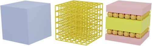
Printing parameters, which control both the slicing software and motion control system, must be optimised for a chosen material to ensure successful and reproducible results. To contextualise the discussion of the printing parameters, we first introduce three general print architectures that are typically used for DIW of HLS: fully dense, lattice and multi-material architectures (). Fully dense prints are important for applications in construction, pharmaceuticals and energetic materials and are often considered as the relevant drop-in replacements for materials made by typical manufacturing methods. A key consideration in developing a printing process for fully dense architectures is avoiding voids between the filaments. Jang et al. showed that the layer height, print speed and extrusion rate influence the line width, while the layer height is the main driver for void formation in the dense prints. There was a critical layer height below which, the ink spreads to fill gaps between filaments, but above which voids were formed between the printed filaments [Citation85].
Figure 4. Illustration of fully dense (left), lattice (middle) and multi-material (right) printed architectures.
Another shape commonly printed with DIW is the lattice or scaffold architecture. Due to the capability of DIW to print highly loaded suspensions with shape-retention capabilities, many complex porous structures can be built. Lattice fabrication is a popular fabrication method for bioceramic applications since the printed multi-scale porosity lattice implants are advantageous for the growth of human tissues [Citation86–92]. In scaffold designs, line spacing between the printed filaments enables easy tuning of the final density or porosity as well as the mechanical strength of the cellular scaffolds [Citation93]. Many works show millimeter-sized scaffolds using micron-sized nozzles; however, building a larger scaffold with finer internal features may be more challenging. In designing lattice prints, key processing considerations include design of a print path to provide appropriate support to spanning or floating filaments. Additionally, solidification kinetics become very important, with a requirement for a solidification time that is comparable to the time for the nozzle to cross the gap [Citation94].
One of the advantages of 3D printing is the ability to produce multi-material objects, especially functionally graded materials, something that is difficult to do with traditional manufacturing processes. The gradients are typically in porosity or composition, which translate to gradients in properties such as hardness, burn rate, compressive strength, etc. Two approaches are used to create prints with gradient pore sizes: (1) for macropores, using lattice architectures with changing spacing and (2) for micropores, using particle-stabilised foams to create air pockets with tunable sizes set during an emulsification process. An example of these approaches is shown in Minas et al., where alumina particles with polyvinyl alcohol (PVA)/water binder (46–53 vol% alumina) is subjected to a foaming process and prints with up to 94% porosity were prepared. Gradients between filaments were set by combining inks with different droplet/bubble sizes [Citation95].
Mixing of two suspensions just before or within the extrusion nozzle is a common approach to prepare gradients in composition. An example with relatively highly loaded suspensions (70 wt% barite and kaolinite powders in wax-based binders) shows that they were able to be mixed with a stirred screw nozzle using appropriate additives to aid in the mixing and dispersion, producing final structures that have a gradient in the ratio of barite to kaolinite [Citation96]. Similarly, formulations of 52 vol% Al and 47 vol% CuO were actively mixed with a rotational mixer in the nozzle to prepare on-demand mixed material prints. It was determined that complete mixing occurred when the ratio of the residence time to mixing time was greater than one, which for this design was 923 rpm, and that this corresponded well to performance of the materials as thermites [Citation97]. This work was also extended to study the active mixing process for fluids with very different viscosities and densities and demonstrated that it was possible to mix non-Newtonian inks with different viscosities and densities using a rotating impeller micromixer [Citation98]. An interesting study to produce materials with both porosity and composition gradients for bone scaffolds used ZrO2-based suspensions (40 wt%) that were put through a process to prepare a foam and combined with alumina toughened zirconia (ATZ) slurries (60 wt%) prior to printing. Foam properties controlled the pore sizes, while mixing the ATZ suspensions and ZrO2 foams immediately before the nozzle led to gradients in composition [Citation99].
For creating any of the common printed architectures for HLS, processing parameters including extruder type, nozzle size and geometry, extrusion rate, print head speed and layer height must be selected to obtain a quality print. Though definitions of ‘quality’ can vary based on the application and the desired final structure, in general a quality print includes a printed part with good shape fidelity, a solid part, predictable voids and stable particle distributions, often homogeneously dispersed throughout the filament. In the rest of Section 3, we will discuss the extrusion design and printing parameters and the elements of their design that impact the print quality for HLS.
3.1. Extrusion design considerations
DIW is a sub-type of material extrusion additive manufacturing and it requires extrusion of an ink from a nozzle and deposition in a layer-by-layer fashion. For the printing to be successful, the ink must be able to be extruded in a smooth path and include stops/starts for moving between layers. The success of this is a function of the ink itself, as described Section 2, but it is also a function of the extruder and nozzle design. We discuss both of these aspects in the following subsections.
3.1.1. Extruder mechanism
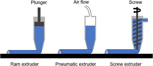
Movement of the ink out of the nozzle is driven by the extruder. In DIW research, three common extrusion systems exist: a ram extruder [Citation16,Citation20,Citation28,Citation33,Citation66,Citation87,Citation88,Citation91,Citation100–109], a pneumatic extruder [Citation15,Citation27,Citation110–114], and a screw extruder [Citation29,Citation105,Citation115–120] (). We first discuss how these systems operate and the relevant parameters for each, before delving into a comparison of the techniques and optional modifications of the extruder. For ram extrusion, a motor drives the positive displacement of a plunger into a syringe of ink, causing a pressure build up that induces flow out of the nozzle. The flow rate for this system can be controlled by the stepping motor speed, which translates to the plunger velocity. For a pneumatic extruder, ink flow is controlled by the application of a uniform pressure to the syringe reservoir, generally by way of compressed air or similar methods. Lastly, for a screw extrusion system, also called an auger extruder, a rotating spiral-shaped screw is utilised to move material from a continuous feeding inlet, which is usually attached to an additional ink reservoir. Here, the angular velocity of the auger is a key parameter in determining the ink flow rate.
Figure 5. Common methods of ink extrusion: ram extruder, pneumatic extruder and screw extruder.
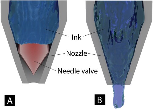
Due to the nature of layer-by-layer printing, DIW requires a halt in ink flow between layers to allow for repositioning of the printing bed or printing head prior to the subsequent layer. After the movement has been made, ink flow must begin again without any delay to or change in the flow rate. This is particularly challenging for HLS inks for two reasons: (1) there is significant cohesion in the filament and a clean break at the end of a layer is challenging and (2) due to the high yield stress, a pressure builds up as printing is initiated and the ink that extrudes after a pause in extrusion can come out faster than the steady state extrusion rate. This startup behaviour was demonstrated to be significant for HLS with highly viscous binders [Citation73]. For ram and pneumatic extruders, a needle valve extrusion mechanism () can be employed to improve deposition precision and control of DIW inks. With this adjustment, a needle or gate valve is located near the nozzle exit and can be actuated by a separate parameter to start or stop extrusion. These valve systems are already widely used in dispensing applications such as soldering and packaging and have been increasingly applied in DIW applications [Citation16,Citation20,Citation121,Citation122].
Figure 6. DIW nozzle with a needle valve in the (A) closed position, preventing ink flow and in (B) the open position, allowing ink to flow.
When comparing extruder types, screw extruders are typically favoured with higher viscosity inks, because the higher contact area of the screw compared to the area of a plunger improves the transport of the ink [Citation123]. Li et al. [Citation16,Citation20] investigated start-stop accuracy as well as printed filament consistency for a high solid loading (∼60 vol%) alumina paste, comparing results for a ram extruder with and without a needle valve, and for an auger/screw extruder. By printing dashed lines using different extruders, they determined that using a needle valve or an auger/screw extruder showed superior accuracy in terms of the extrusion start and stop performance compared to a ram extruder without a needle valve. In addition, by printing continuous lines, they determined that the auger/screw extruder showed a more robust flow consistency overall, based on the line width measurements, than the ram extruder with the needle valve. This was attributed to a relatively small amount of ink being pushed near the nozzle exit of the auger/screw extruder, compared to the entire volume of ink in the ram extruder configurations [Citation16,Citation20]. In addition, inhomogeneity of the ink properties due to high solid loading can cause variation in continuous extrusion forces under a constant plunger velocity, leading to flow rate fluctuation in continuous lines. However, the flow rate fluctuation of the auger/screw extruder is negligible due to its very small operation volume [Citation16,Citation20]. Thus, auger/screw extruders are decidedly less sensitive to the heterogeneities and defects commonly found in HLS inks and imparted during extrusion.
3.1.2. Nozzle geometry
In addition to the extruder design, both the size and the specific geometry of the nozzle set the extrusion path dimensions and dictate the printing pressure. Regarding nozzle geometry, circular nozzles are commonly used to extrude filaments, however nozzle tips with square and hexagonal shapes have also been designed and successfully utilised [Citation124]. The two most common nozzles are straight, or ‘standard’, and conical or ‘cone’ tips. Conical nozzles are generally agreed to have superior capacity and extrusion rates [Citation114,Citation125]. According to Benbow's flow model, the conical tip diminishes the dead zones along the extrusion path, thereby decreasing the printing pressure [Citation126,Citation127].
Experimental results confirm that a conical tip requires less pressure to extrude slurries and quickly reaches a steady-state flow. shows an example of this for a 47.03 vol% hydroxyapatite ink [Citation128], where the extrusion load for a standard tip with a straight barrel and straight nozzle is significantly higher than when a cone-shaped nozzle tip is used. This allows a broad range of extrusion rates to be used simply by controlling the applied pressure. In situations where extrusion pressure to induce flow might be high, as is the case for HLS inks, a conical nozzle tip can be more favourable than a straight tip, while a straight tip might be more favourable when high extrusion pressures are available but unique tip sizes are needed, since fewer options for conical nozzles are commercially available. In addition to the use of a conical nozzle tip, the resistance of the ink to flow was shown to be lower when high-amplitude ultrasonic vibrations are used within the nozzle. Clay and aluminium-polymer mixtures with viscosities up to 14,000 Pa.s were printable using ultrasonic vibrations (f = 30 kHz) with high amplitudes (Ap−p > 1 μm) [Citation111].
Figure 7. Load vs. time curves of standard and conical nozzle tips with a 47.03 vol% hydroxyapatite ink [Citation124]. Reprinted from Direct write assembly of calcium phosphate scaffolds using a water-based hydrogel, Vol 6, J. Franco, P. Hunger, M.E. Launey, A.P. Tomsia,E. Saiz, Acta Biomaterialia, Pages 218–228., Copyright (2010), with permission from Elsevier.
![Figure 7. Load vs. time curves of standard and conical nozzle tips with a 47.03 vol% hydroxyapatite ink [Citation124]. Reprinted from Direct write assembly of calcium phosphate scaffolds using a water-based hydrogel, Vol 6, J. Franco, P. Hunger, M.E. Launey, A.P. Tomsia,E. Saiz, Acta Biomaterialia, Pages 218–228., Copyright (2010), with permission from Elsevier.](/cms/asset/38f46521-e5af-4e21-9bae-fa29ee14eb23/nvpp_a_2279149_f0007_oc.jpg)
With regards to the nozzle diameter, this parameter determines the shear applied to the ink and thus impacts the rheological properties, as well as places limits on the particle sizes able to be extruded. The main consideration for selecting a nozzle diameter for HLS inks is to achieve the best feature resolution while ensuring continuous extrusion without clogging the nozzle tip. A typical rule of thumb to prevent clogging is for the nozzle diameter to be at least 10 times larger than the diameter of the dispersed particles [Citation27,Citation111,Citation120,Citation129–131]. Although clogging can be alleviated by using larger nozzles, this adversely impacts the minimum achievable feature size and print resolution. The resolution and minimum feature size for a print is directly proportional to the nozzle diameter, and DIW literature in the high particle loading regime typically consists of filaments with diameters in the hundreds of microns [Citation31,Citation113,Citation132]. This is likely due to the relative ease of reaching very high particle contents with macroparticles rather than nanoparticles, as macroparticles have lower surface area to volume ratios and thus result in less friction during flow. However, additive manufacturing of HLS with nanoparticles and small feature sizes has been demonstrated, such as Li and Lewis achieving feature sizes as small as 30 µm using 30 nm barium titanate (BaTiO3) nanoparticle ink (50 vol%) [Citation106]. Therefore, determining the proper printing geometry is heavily dependent on ink formulations, and may require trial and error.
3.2. Printing process parameters
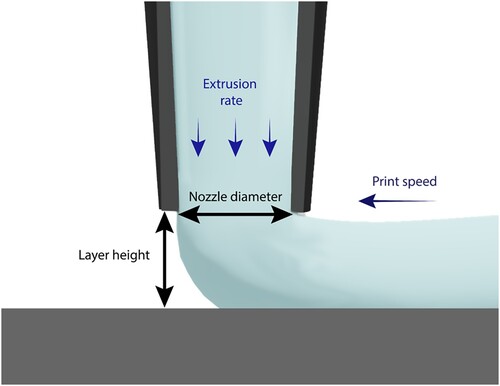
Print quality and structural integrity are directly influenced by the printing conditions selected by the user. Common machine parameters that users often manipulate are layer height, print speed and extrusion rate (). In a simple view of the process, the ink flows through the nozzle at a controlled extrusion rate with a given layer height (stand-off distance) from a print surface or previously deposited layer while moving the nozzle at a specified print speed. Each processing parameter can contribute to the level of extrusion performance, which impacts the print quality.
Figure 8. Illustration of direct ink write printing of a first layer showing important process parameters including the layer height, nozzle diameter, extrusion rate and print speed.
It should be noted that the proper selection and control of print parameters is an important step to produce high fidelity and quality structures. Geometric features from the extruded lines such as line width, line height and cross-sectional shape and area can be examined to understand the role of print parameters, thereby calibrating a printer to produce smooth and consistent flow. Previous studies have measured the width of continuous printed lines to investigate the flow consistency and show that variation of the line width can indicate under-filling and over-filling of material [Citation15,Citation16,Citation20,Citation31,Citation73]. For example, Morissette et al. plotted the height and width of printed lines using laser profilometry scans to explore the optimum operating range of process parameters where the machine can produce the uniform printed lines [Citation133] and Thornton examined the cross-sectional geometry of a printed line and compared it with the ideal slab-shape of a bead cross-section [Citation134]. In this section, we examine the most important processing parameters: extrusion rate, print speed and layer height and their effect on print quality for HLS.
The extrusion rate can be quantitatively described by the extruded volume of ink per unit time and is related to the amount of extrusion pressure required to force out the ink. The resulting extrusion rate depends on the ink formulation, the ram extruder velocity or pressure in the pneumatic extruder and barrel/nozzle geometry. However, the driving factor for choosing an appropriate extrusion rate stems from how much ink is needed to fill the volume defined by the nozzle diameter, layer height and print speed. Here, we discuss the effect of the extruder velocity or pressure, assuming a given geometry and ink. The extrusion force required to print HLS inks is high compared to low-viscosity inks, so an understanding of the full operational range of extrusion rates is crucial prior to full-scale manufacturing. For example, Chan et al. showed that printing with 50 vol% solids (compared to 25 vol% solids) required a larger print pressure:print speed ratio, indicating that for a given print speed, a higher pressure was required to print 50 vol% particles than 25 vol% particles, a trend they tied to the storage modulus of the inks [Citation135].
Printing at extrusion rates that are too low may lead to unstable material flow through the nozzle due to the presence of wall slip. Yilmazer et al. studied the capillary flow of highly loaded suspensions and found that, while large-scale migration of particles was prevented by other particles in the suspension, there was still small-scale migration of the particles away from the wall of the capillary. This led to a fluid/binder-rich zone against the wall and a particle rich zone in the centre [Citation136] and an effective filtering out of the binder. This binder filtration effect was further examined and it was found that it could be mitigated by a higher extrusion rate or a larger diameter capillary [Citation137]. In addition, if the extrusion pressure and resulting extrusion rate are too low, it may lead to nozzle clogging as the HLS ink dries within the nozzle, and the flow rate diminishes until no material can be extruded [Citation15]. Conversely, printing with high pressures may result in excess spreading of the ink, which can lead to an overfilling of print features, and phase separation of particles and binder [Citation138–140]. In this case, the friction between the particles, exacerbated by the high pressure in the extrusion nozzle leads to a granular skeleton through which fluid is filtered [Citation140]. Overall this shows a need to balance these effects and find an optimum extrusion pressure and extrusion rate for a given ink and nozzle geometry.
The extrusion mechanism for the screw/auger system is different than that for the ram or pneumatic extrusion but it is well-established and understood based on widespread screw extruder use in paste and polymer processing. The rotation rate of the screw, also quantified by the angular velocity, sets the extrusion rate and the plates of the screw drag the fluid towards the wall, leading to pressure to move the fluid forward. This results in most of the stress being directed to the screw and barrel and not the fluid, which can decrease phase separation that can be seen in the ram and pneumatic extruders [Citation123]. However, design of the screw to prevent dead zones and particle trapping, remove air bubbles, provide mixing if needed, and provide homogeneous fluid conveying is challenging. Additionally, the screw-based system can apply a high shear on the fluid, damaging sensitive materials and leading to shear-induced heterogeneities and can lead to backflow in the gaps between the wall and the screw [Citation141]. Overall the simple extrusion operation based on the rotation rate is beneficial once the screw design has been optimised for a given formulation.
The print speed is the rate at which the print head moves in space, and it is considered in conjunction with the extrusion rate so that a system can deliver the proper volume of material to fill the programmed toolpath. At a constant extrusion rate, a faster print speed leads to a thinner and stretched filament that can underfill the tool path, while a slower print speed leads to thicker filament or overfilling, similar to the trends found with FDM [Citation142–144]. When the print speed is too high for the extrusion rate, the filament is elongated after it has been deposited and becomes more unstable and disconnected, deteriorating the print quality [Citation145]. While a higher print speed increases productivity, it can also decrease print accuracy due to vibrations and positioning errors [Citation146]. On the other hand, if the print speed is low in comparison to the extrusion rate, the moving nozzle compresses and forces the ink to spread, which may result in wider lines than desired or may be deliberately used to control void fraction [Citation85]. Studies report that the 1:1 ratio between the extrudate linear velocity (exit velocity of ink from the nozzle) and print speed is desirable so that the ink leaves the nozzle and is immediately deposited [Citation125,Citation147–151].
The layer height is the distance between the nozzle and substrate or previously deposited layer. It is an important factor that affects the filament size and shape and the bonding of the newly deposited layer to the substrate or existing layer. At a very low height, the space between the nozzle and print surface is limited compared to the volume of ink extruded and the resulting filament is wider than the nozzle diameter and compressed. Through an empirical study using a high solid-loaded slurry by Wang and Shaw [Citation152], a critical layer height () was proposed as
where
is the extrusion rate,
is the print speed and
is the nozzle diameter. This suggests that at a critical layer height, just enough material is deposited between the nozzle and the substrate to fill that space. By printing near the critical height, a more straight-walled filament shape can be achieved, ultimately resulting in a dimensionally accurate multi-layered object [Citation152]. Tang et al. showed that the layer height set to 70% of typical 0.4 mm nozzle diameter exhibited the most uniform lattice structure [Citation114]. Similarly, Wang et al. showed that for fiber-reinforced silicon carbide ceramic matrix composites with 50 vol% particles structure retention in DIW printing was best if the layer hight was 60–75% of the nozzle diameter.[Citation153] If printing below the critical height, the ink is forced to spread and the angle between the filament and the substrate driven by compression by the nozzle. In contrast, when printing above the critical height, the rheological properties and wettability of the slurry determine the cross-sectional geometry [Citation85].
The layer height and shape are not the only print quality elements impacted by the layer height print parameter. Since the geometry of the lines affects the surface area for bonding to the substrate or between layers, the layer height also impacts the adhesion of layers. At layer heights larger than the nozzle diameter, the extruded filament shape becomes more similar to the circular nozzle tip and the contact area between layers decreases, resulting in weak interlayer bonding. Furthermore, a very high layer height will increase the travel time of the ink through air, which, for some ink types, promotes solidification before reaching the substrate. This can cause poor adhesion to the substrate or other layers [Citation125,Citation147]. It was also observed that a large initial layer height reduced the bonding with the platform, resulting in the instability of the scaffold and possible dragging of material [Citation154]. Thus, it is often useful to set the first layer height intentionally lower than the layer height for subsequent layers to allow more bonding to the print surface, improving weight support.
Other specific printing defects have been observed when the layer height parameter is not optimised for a particular design (straying too far from the critical layer height value). Too low of a layer height may lead to a groove pattern on the deposited filaments, with a sunken centre where the nozzle cut a path. A low layer height can also increase flow resistance, which hinders the smooth movement of the fluid and can cause back pressure in the nozzle [Citation125,Citation147]. When fabricating a scaffold structure, a low layer height can cause sagging filaments between the overlapping areas and deformation in the contact area, which makes it difficult to customise the porosity [Citation154]. Overall, layer height is a powerful processing parameter to control filament geometry and interlayer adhesion but is prone to causing defects when not used in an optimal range.
3.3. Summary of print parameter considerations
As described throughout Section 3, the role of the printer set-up and processing parameters and how to tune them is relatively well-understood and there are few situations for HLS where knowledge from other material extrusion printing doesn't carry over. However, due to the greater variety of inks and rheological properties in DIW printing compared to FDM, using the knowledge discussed here to actually start a process with a new ink is still slow and done on a case-by-case basis. There is a significant need for further process development to enable automated selection of process parameters and implementation of process control. Achieving this will require a stronger connection between ink properties, such as the different rheological outputs discussed in Section 2, and the necessary process parameters and development of models or data analytics to guide automated design and control.
4. Print solidification and post-processing
DIW printable inks must be flowable during extrusion, maintain dimensional stability once deposited onto a surface, and properly adhere to previously extruded layers. Due to these requirements, rapid solidification is desired after initial extrusion of a liquid-like slurry. Two common routes to solidification for DIW inks are UV cure (photopolymerisation) and solvent evaporation. This section discusses how high solids loadings complicate the pathways to solidification. We also cover post-processing techniques such as debinding and sintering that are particularly common for DIW printing of HLS. The success of these techniques is heavily influenced by the high particle loading.
4.1. UV initiated cure
Ultra-violet (UV) cured binder systems use light to initiate and propagate a polymerisation reaction. This mechanism, known as photopolymerisation, involves a solution of monomers, oligomers and photoinitiators dispersed in a liquid state. The initiators convert photonic energy into chemical energy by forming either free radicals or cations upon exposure to light, which initiate a chain growth reaction in the oligomers and monomers, leading to polymerisation [Citation155,Citation156]. Photopolymerisation has been used to initiate cure in several 3D printing methods including the HLS DIW technique [Citation155]. Common monomers and oligomers used in photocurable 3D printed systems include: (meth)acrylates, epoxies, thiol-enes and thiol-ynes and example chemical structures are shown in [Citation155,Citation157].
While there are photopolymerisation reactions that occur in the visible and infrared (IR) range, we focus this discussion on UV-sensitive photoinitiators since UV photon sources are the most commonly used in light-cured 3D printing systems [Citation155,Citation158]. Exposure to high energy UV light can cause side reactions during polymerisation, degrading the reactants and products and leading to lower molecular weights for polymers [Citation155]. Therefore, the selection of a photon source is important for the quality of cure obtained by the photoactive resin. For a more complete discussion of photopolymerisation in 3D printing the authors refer the reader to a comprehensive review by Bagheri and Jin [Citation155]. This review will limit its discussion of photopolymerisation to the effect of HLS on cure quality.
Use of UV-based curing systems is relatively well established in 3D printing. However, there are additional considerations when photopolymerisation is used to cure HLS [Citation155]. The cure depth (Cd) of a photopolymerisation system is a function of the critical energy dose (Ec) and depth of penetration (Dp) through a logarithmic relationship, where E0 is the energy of the light source [Citation157,Citation159].
(10)
(10) Even in resin systems without particles, UV photons typically have a small Dp due to their short wavelengths, 100–400 nm, leading to a Dp is generally less than 100 µm, so UV-light sources usually cannot be used to cure multiple extruded layers concurrently [Citation155]. Since the preceding layer must be activated for cure before the next layer can be extruded, the maximum achievable print speed for UV cured DIW is slow compared to other techniques, particularly if a large, printed structure is desired [Citation155]. In HLS DIW, light attenuation due to particle interactions is significant and affects the Dp and final Cd of a print [Citation159,Citation160]. The specific particle volume fraction, size, and refractive index of a suspension can significantly alter the Cd of a printed part through absorption and scattering [Citation160–162].
For opaque suspensions, such as HLS, the attenuation or dampening of photons travelling through a material is dominated by scattering phenomena, with absorption playing a relatively minor role in determining Dp and therefore overall cure Cd [Citation162]. When the solids loading of a solution is increased, the path length of the light (L) is decreased due to increased scattering [Citation163]. Thus, increased particle loading leads to faster light attenuation, a smaller Dp and a correspondingly lower Cd [Citation164]. Beer's law dictates that the intensity of light in an interacting solution can be calculated from L and the starting intensity. For Beer's law to be valid for multi-particle scattering, the distance between particles must be greater than two radii [Citation162]. However, as long as there are spaces between particles of roughly one particle radius the multi-particle form of Beer's law is still useful as a predictive tool [Citation162]. The multi-particle scattering equation for Beer's law shown in Equation (11) can be used to estimate Dp for a given particle size, volume fraction and refractive index [Citation160,Citation162].
(11)
(11) where <d> is the average particle diameter, Φ is the volume fraction of the particles, and Q is the extinction coefficient efficiency. Q depends on a variety of factors including the refractive index contrast (Δη), Φ, and <d>. Q defines the scattering behaviour of a solution and there are several theoretical equations that may be used to find Q based upon the scattering environment [Citation162]. Experiments by Griffith and Halloran found that scattering efficiency could be described moderately well by taking the square of the refractive index difference such that Q = Δη2/η02, though this accuracy was often only within an order of magnitude and did not account for the effect of particle size [Citation162].
The refractive indices (η) of the suspended particles and the medium have a large effect on the beam path length and therefore the final Dp and Cd of a suspension [Citation165]. In particular, the contrast between the refractive index of the monomer solution and the particles will dictate cure depth, which varies with 1/(Δη)2 for a constant energy dose [Citation165]. This is because a high contrast between the refractive index of the particles and medium leads to a higher instance of scattering [Citation165]. An alternative expression for the penetration depth that captures the effects of refractive index contrast and volume fraction of particles can be given by Equation (12) [Citation165]:
(12)
(12) where β is a fitting parameter that correlates strongly with the refractive index contrast, Φ is the volume fraction of particles in suspension, cP and cD are the concentrations of the photoinitiator and dye, and ϵp and ϵD are molar extinction coefficients of the photoinitiator and the dye [Citation165].
Scattering and absorption of UV light in HLS can also be described using a modified Mie scattering approach. The Mie solution to Maxwell's equations for a homogenous spherical particle interacting with a planar electromagnetic wave traditionally deals with dilute suspensions of colloidal particles [Citation166]. However, some effort has been made to quantify multiple scattering effects for HLS in excess of 50 vol% by considering structure factor contributions to quantify the effect of interparticle interactions on scattering [Citation167]. This structure factor S(q), given by the Fourier transform of the particulate radial distribution function, allows for successful modelling and prediction of cure depths [Citation167,Citation168]. Whether predicting the depth of UV penetration using the estimates from Beer's law or calculating scattering using the modified Mie scattering approach, all existing models are limited at very high particle loading where the scattering is high and penetration depths low. Improvements in these models will be valuable, especially for emerging applications with high solids loadings, but low feature sizes, where the dimensions of printed lines might be sufficiently low for good UV penetration. Obtaining full cure in these systems, however, may still require special polymer binders with matching refractive indices or particle features that reduce scattering.
Although the limitation to depth of cure imposed by scattering from the high particle loading is the most frequently encountered challenge in UV cure of HLS, another photopolymerisation parameter is affected by the presence of particles. For any photopolymerised system there is a minimum exposure energy required to initiate the polymerisation process. This Ec requirement, included in Equation (10), varies with the chosen polymer system formulation, including decreasing with the volume fraction of the solids [Citation159]. This means that for HLS, the energy needed to start the polymerisation can be lower than for binder alone and can lead to unintended polymerisation. The Ec may be increased by the use of inhibitors intentionally added to the monomer solution to prevent accidental polymerisation and stabilise the solution against inadvertently generated free radicals [Citation159]. For UV doses smaller than the Ec, the inhibitor will absorb any free radicals generated, preventing a polymerisation reaction from taking place [Citation159,Citation165].
The linearised inhibitor exhaustion model makes several predictions about the relationship between Ec and the volume fraction of particles (Equation 13).
(13)
(13) Where
is the volume fraction of solid material, Ω is the quantum yield, h
is the photon energy, γQ is the potency of the inhibitor, Q is the concentration of the inhibitor, O is the concentration of the oxygen inhibitor, γo is the potency of the oxygen inhibitor, γD is the number of radicals that did not get generated due to absorption by an inert dye, cD is the molar concentration of the dye, cP is the molar concentration of the photoinitiator, and ϵP is the molar extinction coefficient of the photoinitiator [Citation159].
This model shows that Ec decreases linearly with the volume fraction of the suspension that is the particles, assuming that the only effect from the particles is to decrease the volume of the binder [Citation169]. It assumes that Ec is independent of particle size or shape, implying that all particles should behave roughly the same at a given volume fraction loading and that the particles themselves do not act as free radical absorbers [Citation159]. The decrease in Ec with particle loading indicates that less UV energy would be needed to get a higher cure depth, a trend that works counter to the scattering effect discussed previously. Since scattering effects are so strong in high solids systems, especially those with microparticles and poor refractive index matching between particle/binder, the conditions for many applications, the overall trend for high solids materials is still to have lower cure depths with increasing particle volume fractions.
Thus far, we have focused on the impact of particle volume fraction on the UV cure, in particular depth of cure and energy to start the polymerisation. But, the particle composition, including particle size, size ratio and mineralogy, can also impact the curing of the binder.
Firstly, smaller particles (100–101 μm and smaller colloidal particles) have a larger scattering effect than larger particles (102 μm and above). This is due to a larger surface area to volume ratio and means that for a set solid loading, the Dp decreases with smaller particle diameter [Citation170]. Since most HLS make use of multimodal ratios of particle sizes to improve packing, the smallest particle size that can be used is constrained by the depth of cure required for the printing process. For sufficiently small layers (102 μm and below) particles smaller than 101 μm are appropriate [Citation171]. However, for larger layer heights, the inclusion of these particle sizes significantly limits the level of solidification of each layer. In contrast, using larger particles to achieve larger cure depths can minimise light scattering [Citation172], but these particles will also require larger layer heights to be fully incorporated within each layer. In addition, with larger particles, the packing efficiency may not be as optimal. As such, if the photopolymer binder is burned off during post-processing, parts composed with larger particle sizes can present significant porosity. Particle size and size ratios are therefore a tradeoff between maximising solid loadings or part densification and optimising curing during printing to maintain shape fidelity.
As previously mentioned, matching refractive indices between the particles and the binder is a good solution for producing sufficient cure depths despite high solid loadings. But this is unrealistic considering the wide range of solid particles that are of interest for DIW printing. For example, most photopolymers have refractive indices around , but for solids, the refractive index could range from
for SiO2 to
for TiO2 within the range of UV light [Citation173]. When solids are composed of a combination of metal oxides, as is the case for simulants recently developed to imitate Lunar regolith (i.e. Lunar Highlands Simulant, LHS-1, prepared by Exolith Lab) refractive index matching with a photopolymer binder is not easily achievable, as most high refractive index polymers capable of undergoing UV cure are limited to
[Citation174], Also in the case of regolith simulants, minor changes in the particle mineralogy, and the relative ratios of metal oxides, can result in significant changes in the reflection of light, as seen in for Highland and Mare types of regolith simulants. The applicability of UV cure solidification is therefore limited to shorter layer heights and/or lower solid loadings for these types of ink formulations [Citation175].
Figure 9. Examples of acrylate monomers (polyethylene glycol diacrylate, PEDGA and hexyl acrylate, HA), thiol-ene monomer pairs (trimethylolpropane tris(3-mercaptopropionate, TMPMP and triallyl-1,3,5-triazine-2,4,6 (1H,3H,5H)-trione, TTT) and epoxy monomers (3,4 epoxycyclohexane)methyl 3,4 epoxycyclohexylcarboxylate, EPOX and bisphenol A diglycidyl ether (DGEBA).
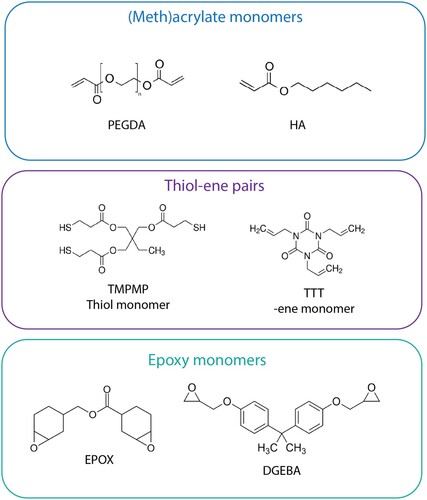
Although much of the focus of study in UV cure process optimisation for HLS has been on improving depth and degree of cure, the width and profile of the beam exposed to the printed ink is also important. 3D printing systems often use a rastered laser beam to initiate UV cure. These laser beams have a Gaussian intensity distribution, which can be quantified so that scan spacing of the laser path can be determined and Ec can be reached for all deposited resin. For a laser beam with a Gaussian intensity distribution, line width can be calculated for unfilled resin using principles of Beer-Lamberts law, but, similar to cure depth, the increased scattering of HLS complicates predictions for cure width (Cw). Cw like Cd, is dependent on particle size and vol% loading in a suspension [Citation163]. An empirical model proposed by Hinczewski et al. considers the initial beam profile of the laser as well as the ceramic suspension properties of a slurry to predict the cure width, CW,Hinz, of a ceramic particle suspension [Citation157]:
(14)
(14) where Emax is the peak energy and F1 and EHincz are fitting variables specific to the material parameters and initial Gaussian beam width of a given process. This model is useful if the light source used has an intensity distribution that is Gaussian in shape but is not valid for other light source distributions [Citation157,Citation163]. Other models have also been proposed that expand on the broadening due to scattering effects, such as that by Gentry and Halloran [Citation163].
Although the physics that controls the cure of UV binders in opaque and highly loaded suspensions is still not fully understood, strict process parameters and controls allow for reproducible and consistent manufacturing and cure in many labs, and in the last decade, much progress has been made towards understanding the salient physical processes that control cure quality [Citation73,Citation173,Citation176]. Opportunities for new advancements include developing binders with high refractive indices to better match many particle types, designing new photoinitiators to work at a wider range of wavelengths and developing scalable particle coating technologies to decrease reflectance and absorption of the UV light.
4.2. Solvent initiated cure
Solvent evaporation is commonly used to induce solidification in HLS DIW [Citation73,Citation176,Citation177]. Solvent-based HLS systems typically consist of particles, a dispersant, a binder, and a solvent [Citation178]. The solvent enables material flow during extrusion and evaporates upon deposition to help the suspension maintain its shape [Citation178]. The dispersant prevents particle agglomeration and minimises inter-particle friction as the material is forced through a constricting nozzle [Citation179]. Binders are used to improve both printability and green body robustness of a print. Though binders and dispersants are common, they are not required and research groups have successfully printed HLS using only particles and solvents [Citation176,Citation177].
A significant challenge in printing with solvent evaporation methods for solidification is achieving appropriate rheological properties (basic principles discussed in Section 2). Early printing studies of HLS found that for solvent cured suspensions to be printable, a transition from the pseudo-plastic viscosity regime, which allows for shear thinning and flow during extrusion, to the dilatant or shear thickening regime, must occur [Citation178]. Shear-thickening behaviour allows the suspension to retain its shape and act as a solid after deposition, ensuring many layers can be deposited [Citation178]. This transition from pseudo-plastic to dilatant viscosity behaviour is defined in a printed structure as the dilatant front and it should occur for each layer in the printed structure as it cures in order to support the subsequent layers [Citation178]. However, enough solvent should remain in the most recently printed layer such that adhesion is promoted between it and the next layer to be deposited.
For solvent-initiated cures, the dilatant front drives both print stability and build times and its progression depends on the volatility of the solvent. HLS prints that utilise an aqueous or similarly non-volatile solvent typically experience slow drying times or require heat to dry at an acceptable rate [Citation178]. While systems that use highly volatile solvents such as methyl ethyl ketones (MEK), dichloromethane (DCM), etc. may be subject to increased clogging and lack of layer adhesion if not printed rapidly [Citation173,Citation177]. Further, many of these highly volatile organic solvents must contend with toxicity issues, though milder solvents such as methanol have been successfully applied [Citation73,Citation180,Citation181].
One approach to achieve the balance between solidification time, clogging and adhesion is to use a graded volatility system, or a mixture of solvents with different volatilities [Citation177,Citation182,Citation183]. The benefits of a graded volatility solvent were touched upon in studies by Jakus et al. In their study, the authors qualitatively compared the particle distribution of a hydroxyapatite- poly(lactic-co-glycolic acid) (HAPLGA) composite printed from a graded volatility solvent and a HAPLGA composite that underwent solvent cure using only dichloromethane (DCM), which is extremely volatile [Citation177]. The HAPLGA composite fabricated with only DCM displayed a discontinuous coating of binder material and evidence of solvent popping compared to the HAPLGA composite fabricated from a graded volatility solvent [Citation177].
There are few studies on the kinetics of solidification and devolatilisation in HLS. Most discussions of solvent choice for DIW centre on creating a solution that has adequate shear-thinning and rheological properties for printing [Citation73,Citation184]. Despite little investigation of solvent evaporation specifically in HLS DIW, drying of particle suspensions has been studied for many years due to its relevance in latex paints [Citation185]. In paint-like suspensions, which have a lower solids content (e.g. 38 vol% for Rohm and Haas W-88–16) and viscosity than the HLS we discuss here, the drying occurs through two stages: (1) evaporation of solvent from a wet inner layer through a growing denser outer layer and (2) diffusion limited transport of solvent. The second stage is thought to occur after the outer later solvent content reaches 8% based on percolation theories [Citation185]. For the first stage and for many lower solids suspensions, two processes compete that determine the distribution and microstructure of the particles in the resulting solid. The first is the evaporation rate and the second is the diffusion coefficient of the particles in the suspension. The timescales for each of these are used in a dimensionless number, the Peclet number, to characterise the controlling factors in the system [Citation186–188].
In very high solids systems, the diffusion of the particles is minimal compared to the evaporation and the behaviour more resembles that of ‘skin formation’ that occurs in rapidly evaporating colloidal particle dispersions (A) [Citation186]. In the coatings industry, skin formation often leads to defects, including buckling and cavitation. As the solvent evaporates, the skin is compressed, leading to mechanical instabilities that cause the skin to wrinkle or buckle [Citation34]. At times, the elastic energy that builds up due to the compression can be released as gas bubbles through a cavitation process, such as that seen in 3D printed samples of PVP, glass and methanol (B). Finally, though the mobility is low in the highly loaded suspensions, phase separation can still occur on drying, where the polymer may separate from the particles and provide poor binding in the solid product. This type of behaviour has been reported when there are weak particle-polymer interactions and dense aggregates of bare particles form in the dried film surrounded by polymer-rich areas [Citation189]. Controlling particle-polymer molecular interactions can improve homogeneity of the particle distribution in the dried material.
Figure 10. Percent reflectance measured in the UV-visible spectrum for Lunar Highlands Simulant (LHS-1) and Lunar Mare Simulant (LMS-1) particles sieved to <35 μm. The Lunar Mare Simulant is more reflective at 365 nm, a typical UV wavelength for 3D printing.
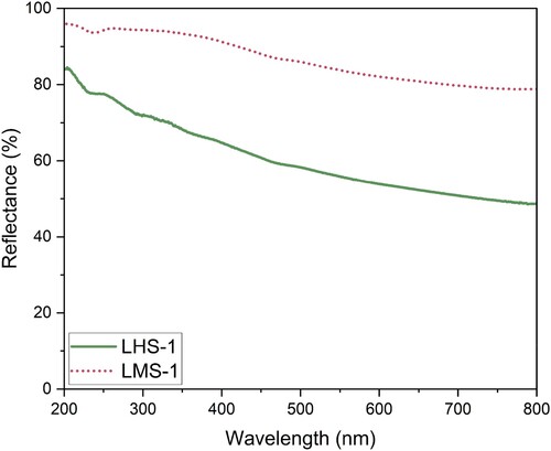
Figure 11. (A) Skin formation in an evaporating slurry and (B) Void left by cavitation bubble from stresses in the skin layer.
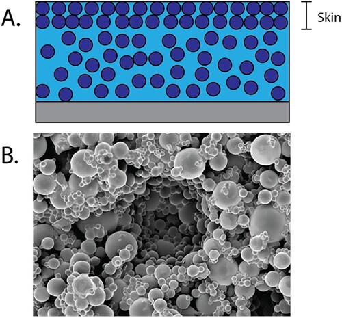
Though significant work has been done to understand evaporation and microstructure in the skin layer of colloidal polymer films, there has been little investigation of drying in films or other shapes that are composed of a high density of particles throughout their entire thickness. This presents interesting and unique scientific challenges including the diffusion of solvent through tortuous paths, the role of particle-polymer molecular interactions with low mobility and whether further compression of the highly loaded suspension occurs and can lead to buckling or cavitation defects. A thorough study and development of metrics to understand the drying and solidification of the final printed part is essential to development of solvent evaporation-based processes that can reliably print the wide diversity of inks of interest for DIW HLS.
4.3. Debinding and sintering
For many HLS DIW applications, particularly those that involve advanced ceramics or metallurgy, additional post-processing may be necessary to manufacture a viable product. If a binder was used during initial printing steps, it may need to be removed either through a chemical or thermal debinding process to remove the polymer before densification and sintering of particles can proceed (). Factors such as particle size distribution, particle shape and volume loading all play a part in the debinding process and final sinter quality [Citation190–192]. HLS DIW materials containing small, spherical particles with a multi-modal size distribution, and high packing density are generally well suited for debinding and sintering with minimal porosity [Citation190,Citation193]. Conversely, those materials with large or abnormally shaped particles, a mono-modal size distribution and correspondingly low packing density are subject to incomplete sintering, high porosity and excessive shrinkage.
Figure 12. The stages of post-processing to remove binder and densify ceramics and metals including debinding (a. thermal and b. chemical), c. sintering and d. densification.
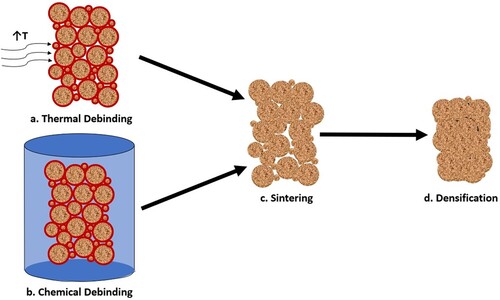
The debinding and sintering processes used to manufacture HLS DIW parts are nearly identical to those used for metal injection molding (MIM). It should be noted that MIM uses molds to form components and must therefore contend with significant internal stresses that are not expected to be present in extruded HLS DIW green bodies [Citation194]. Further, the particle distribution between MIM and HLS DIW parts may be significantly different due to their unique manufacturing approaches. The literature at present has not widely explored how HLS DIW debinding differs from that of MIM debinding processes, and so we report on debinding of both manufacturing processes interchangeably as the underlying physics is expected to be largely similar and MIM provides an exceptional starting framework for further study of HLS DIW debinding phenomena [Citation194,Citation195,Citation196].
As an alternative to thermal debinding, or as a combination step, chemical or solvent debinding is widely used in industry and by many commercialised extrusion metal printing companies, such as MarkForged and Desktop Metal. Organic binders are removed, or partially removed, by immersing the green body (3D printed composite prior to removal of the organic binder) in an organic solvent, which dissolves the polymer binder [Citation197]. The solvent selected can impact the shrinkage, the bulk density and the porosity of the remaining structure. In one study that examined 10 solvents with 3D printed alumina ceramics, polyethylene glycol was found to provide the lowest shrinkage in the length direction and ammonium hydroxide was found to result in the lowest bulk density and maximum porosity [Citation197]. The solvents used to facilitate debinding are often toxic and may cause significant internal stresses through swelling and deformation of green bodies, though some success with water-soluble binders has been demonstrated [Citation198–200]. Solvent and thermal debinding may be combined, with the solvent debinding occurring after completed extrusion and before the thermal debind, after which the print is sintered [Citation119]. Binder systems may be designed to allow for the removal of low molecular weight binder material in the solvent debinding step, while leaving a small amount of high molecular weight binder to be removed in the intermediate thermal debinding process, once adequate porosity and open porous channels have been created through solvent leaching [Citation200]. Combining chemical debinding with a secondary thermal debinding process minimises the processing time and defects created when thermal debinding is the principal applied process. This effectively provides a method for the creation of robust parts, despite the challenges introduced by high solid contents.
Alternative binder removal methods, including catalytic debinding and wicking, also utilise both chemical and thermal processes to efficiently remove organic binders, though they are more complex and often require specialised equipment and safety protocols [Citation201]. In catalytic debinding, acidic vapour is used to convert the binder mass to vapour. In one common reaction, exposure to nitric acid causes polyoxymethylene binder degradation through attack of the oxygen atoms in the polymer chain, resulting in a low molecular weight formaldehyde which can be easily removed from the printed material [Citation202]. As with other, more common, techniques these alternative methods must consider particle loading, size and size distribution in the design of an HLS suitable for DIW and post-processing [Citation202]. For example, the large surface area to volume ratio for small or irregular shaped particles can make full debinding challenging and slow due to the large amount of surface area of polymer that must be removed per mass of particle material [Citation203].
Key considerations for debinding are how fast it proceeds and whether it is uniform or progressive. Typically the process is modelled through a series model or a parallel model (), depending on the gaseous environment. The series model, also called the shrinking undegraded core structure, assumes that debinding starts at the surface of a part, and proceeds through the mold until reaching the core (illustrated in A) [Citation191]. The rate of debinding in this model depends on the amount of exposed surface area in the part as well as the rate of diffusion of the reactive gas used in debinding [Citation191]. This model is accurate if the atmosphere inside the oven is reactive with the organic binder, such as the degradation of polypropylene binder in an oxygen environment [Citation204]. However, if a neutral gas such as argon or nitrogen is used during thermal debinding, then the parallel, or the uniform distributed porosity model (B), is more appropriate for describing debinding behaviour. In this model, the influence of capillary behaviour on the liquid polymer and pressure from evolved gaseous polymer drives movement of the liquid binder within the part [Citation205]. Liquid binder migrates from large pores and is transported preferentially into small pores or to the edges of the part during the initial stages of the pyrolysis process [Citation206]. Polypropylene undergoing thermal degradation in a nitrogen environment was found to degrade at rates that were independent of part dimensions, highlighting the importance of selecting a proper atmospheric environment to encourage the desired degradation and debinding mode for a given polymeric binder [Citation204].
Figure 13. (A) Removal of binder from the surface inward, called series debinding and (B) removal of the binder starting at internal nuclei, called parallel debinding.
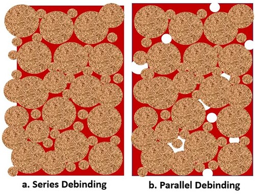
In addition to the rate of debinding, the formation of defects such as pores and cracks during debinding is important when designing a process. Parts made with ceramic particles are more prone to defects during thermal debinding than those made with metal particles [Citation191]. Some hypothesise that this is due to the tendency for ceramic particles to be jagged and asymmetrical in comparison to metal particles, which are generally spherical in shape [Citation191]. This asymmetrical particle geometry leads to inefficient packing and particle rearrangement as the polymer is burned out and causes overall higher internal stresses and pressures in the part [Citation191]. Others hypothesise that the brittle nature of ceramics is the cause for increased defects [Citation191]. Despite poor packing, for all thermal debinding techniques, a high particle loading is desired so that the part may maintain geometry and structural integrity after binder removal is complete and before sintering has progressed.
Another important element to consider when designing the debinding process is that voids can be introduced into a part when the partial pressure of a trapped vapour (due to polymer degradation) exceeds that of the atmospheric pressure [Citation191]. The over pressurisation of a thermal debinding process is dependent on several factors, including the binder removal method (series or parallel), volume fraction of polymer, heating rates and final temperature. The critical heating rate, above which voids are formed, has been well studied and simulated for a variety of polymers for both the shrinking undegraded core and uniform distributed porosity models [Citation191,Citation192,Citation194,Citation195,Citation207]. For HLS, particles serve as nuclei for heterogeneous void formation during these over pressurisation conditions [Citation191,Citation192]. This can present structural weaknesses in final parts after the debinding process, which is undesirable in most applications.
Once debinding has occurred, the parts must be sintered to complete densification. For processes that use thermal debinding, the temperature is increased from the debinding temperature gradually, usually at 2–10°C/min, to the elevated temperatures required in order to melt particles into a uniform phase. Common sintering temperatures include 900–1000°C for Cu, 1500–1600°C for Al2O3 systems, or as high as 2000°C for B4C systems, and it is common to hold this temperature for 1–3 h [Citation20,Citation28,Citation33,Citation66,Citation195]. It is helpful to examine the traditional sintering literature to understand how density can be maximised in printed parts [Citation190]. Connected particles are critical to ensuring there is minimal porosity present in sintered parts after debinding processes are complete [Citation208]. Simulations of DIW manufactured parts show that the final sintered density of a part may be increased by utilising a bimodal particle distribution rather than monomodal distribution [Citation190,Citation193]. Sintering approaches that maximise particle loading and employ a bimodal or higher particle size distribution to achieve efficient packing will yield a fully dense or nearly fully dense part. This is in part due to the higher amount of contacts between particles, and the high reactivity of the smaller particles. Less shrinkage has also been observed with bimodal systems, however it has been noted that pores resulting from sintering of bimodal systems are more irregularly shaped than pores in monomodal systems [Citation193]. It has also been suggested that this phenomenon can result in localised defects where stress can concentrate [Citation190]. Additionally, computational models tracking the spatial evolution of pores during sintering of inks with multi-modal particle size distributions and varying shapes are currently too few and further investigation would be a great advantage to the field.
In addition to defects resulting from the particles themselves, processing of the DIW ink is another aspect that can inadvertently result in defect formation. For instance, the preparation of the DIW ink prior to printing carries implications all the way to the sintering step, where trapped air in the ink prior to extrusion can result in lower sintered density due to the presence of voids. Here, proper degassing steps may need to be implemented prior to printing. In addition, poor sintered density can be a result of improper printing parameters [Citation66,Citation203]. As discussed in Section 3, tailoring the layer height, with the nozzle width, extrusion speed and print speed can help to minimise voids between adjacent extruded filament segments [Citation85]. Another important aspect of processing reflecting on sintering is maintaining a homogeneous particle spatial distribution. As smaller particles are more reactive to sintering, ensuring they are evenly distributed relative to the larger particles helps in producing continuous density gradients across a print during sintering [Citation203]. Likewise, for multi-materials, including particles of different compositions or a single particle type, such as regolith, sintering gradients can be a challenge. For these multi-materials, the sintering temperature is usually chosen based on the dominant species. With this particle type, however, it is also important to consider both the coefficient of thermal expansion and the melting temperature of all components in the bulk chemistry, as uneven shrinkage amongst the components can result in stress fractures [Citation203]. On the other hand, multi-material particles can also result in higher sintering density due to liquid phase sintering occurring when lower melting temperature species are present [Citation209]. Further characterisation of multimodal, multicomponent particle formulations should yield greater and more comprehensive approaches to sintering post-printing and improve the quality and reproducibility of sintered results.
As with debinding and cure studies, while some preliminary research has been done to better understand the effects of particle loading on sintering behaviour in DIW HLS, most research draws heavily from existing technologies and there are few generalised best practices established for these processes with 3D printed parts made from HLS. It is nevertheless understood, as discussed in this section, that the mechanical properties of HLS parts produced via DIW will be negatively impacted with a lower solid packing efficiency, higher void content, weaking bonding across grains. To fully enable DIW as a printing technology for ceramic and metal parts, it is crucial to build a stronger understanding of the driving mechanism that results in loss of mechanical properties, occurring either due to debinding, or sintering. The future of the field will depend in part on such generalised formulation guidelines to optimise the production of robust parts, with greater quality control across prints.
4.4. Summary of solidification considerations
Although inks with high particle contents can often maintain some structure at rest, they still must be solidified for their final applications. One of the strengths of DIW is that many solidification mechanisms are possible, including solvent evaporation, UV cure, thermal cure and debinding/sintering. The different solidification processes are all quite different and come with their own unique challenges and we have discussed those throughout sections 4.1–4.3. Across all methods, common considerations include the rate of solidification, the extent of solidification and the presence of defects such as voids, that impact the properties of the solidified part. To improve process design capabilities, further studies should be done to identify easily-measured parameters that can predict solidification rates and extents and/or final mechanical properties. This can feed into both the initial design of the process and future process control schemes and greatly improve quality control for DIW printed materials.
5. Applications
Having provided a detailed description of the characterisation and formulation of a HLS DIW ink, a discussion of printing parameters and ways to overcome the challenges that arise with processing, and some of the solidification methods and debinding processes, we showcase some of the application spaces in which HLS have been successfully applied. Specifically, we examine the AM requirements for regenerative medicine and rocket propellants. Finally, we provide a holistic analysis of the formulation components and the processing and solidification methods encountered for DIW in a variety of fields.
5.1. Regenerative medicine
Artificial bone scaffolding composites could revolutionise the dental and orthopedic industries and provide quality-of-life improvements for patients suffering from severe bone breaks or bone loss by encouraging bone tissue regeneration. With the right properties, they can replace allografts and grafts harvested by cadavers, but the material properties of bone are challenging to replicate. 3D printed polymer composites are promising scaffolds for bone tissue growth because they utilise biomimicry to encourage bioactivity, allowing for cell differentiation and resorption of the artificial structure as materials are converted to tissue [Citation2,Citation210,Citation211]. The ratio of the bone mineral, hydroxyapatite (HA), to polymer is postulated to be essential in ensuring tissue differentiation and bone regrowth and a high solids loading of HA suspended in a biodegradable polymer shows improved regrowth compared to low loadings. For bone scaffolding composites, the desired particle loading ratio is ∼48 vol% (70 wt.%) hydroxyapatite, which mimics biological loading conditions observed in real bone tissue [Citation2,Citation210,Citation212].
The appeal of 3D printing for composite bone scaffolds is that it can prepare structures that mimic the highly hierarchical nature of bone tissue, with a dense mineralised material encasing a porous ‘spongy’ interior, while also tailoring pore size and shape and controlling interconnectivity between pores [Citation213]. Other manufacturing methods such as gas foaming, solvent casting, salt leaching, freeze drying and thermally induced phase separation do not offer tailored pore size, and interconnectivity tends to be poorly controlled, leading to worse in-vivo outcomes compared to additive manufacturing methods [Citation213]. Optimised porosity is seen as critical for improved outcomes during in-vivo testing and limits the potential for clinical applicability and trials for these materials [Citation5]. Additionally, new advances in compositionally graded high solids 3D printing are promising for mimicking mechanical property gradients in bone, not just pore sizes and spatial gradients in pore size. For example, by varying the ratio of HA to β-tricalcium phosphate (TCP) in polycaprolactone and creating vertical gradients in printed bone tissue composites, gradients in cell growth were encouraged. The amount of TCP in the region changes how rabbit bone marrow-derived mesenchymal stem cells differentiate into osteogenic phenotypes. Higher alkaline phosphatase activity, a marker in early stage osteogenic differentiation, was seen with 20 vol% TCP compared to 0 vol% TCP and this led to a gradient in alkaline phosphatase activity and thus cell differentiation in the vertical direction for the 3D printed scaffold [Citation214]. This is particularly promising because natural bone shows gradients in cell differentiation and growth, but these are not feasible to synthetically produce using other manufacturing methods.
AM techniques for bone scaffolding composites, as well as tissue engineering more broadly, have been recognised as key to advancing the field and current results are promising. However, significant advances in increasing the complexity of customised gradients and structures to mimic the complex nature of bone and other biological growth systems is necessary to truly reach the performance of natural tissue for regeneration. Multimaterial printing and integration of 3D printing with other manufacturing processes, such as electrospinning, which can mimic the extracellular matrix, to produce more complex and integrated scaffold systems is of particular interest for treatment of multisystem injuries and diseases. Throughout all of these innovations, a strong understanding of the material composition and the processing parameters is necessary to provide safe and reproducible treatment and rapidly adapt to specific patient conditions.
5.2. Energetic materials
Another particularly exciting application of high solids DIW 3D printing is that of energetic materials, including solid rocket composite propellants. NASA's current Artemis programme utilises two solid rocket boosters (SRBs) to boost its Space Launch System (SLS) vehicle into orbit. Solid composite propellants typically consist of a powdered catalyst, fuel and oxidiser dispersed in a binder which holds the shape of the propellant together. The shape of a traditionally cast propellant composite, known as the propellant grain, is critical to designing the thrust-time profile of a rocket and maximising the efficiency of the solid rocket booster. Some shape profiles are very challenging to produce using traditional cast-cure techniques [Citation215,Citation216]. Examples of some unusual printed shapes with high solids contents are shown in . Additionally, the particle loading of the propellant at any given point in the propellant grain dictates the burn rate of fuel and the resultant specific impulse at that point in the trajectory. Common particulate materials include aluminium fuel, ammonium perchlorate oxidisers and iron oxide catalysts with particle sizes ranging from tens of microns to up to 0.3 mm, often employing a bimodal or trimodal particle size distribution [Citation217,Citation218]. Particle loading ratios are often found in excess of ∼85% (by weight) to maximise the specific impulse and thrust of the vehicle [Citation219–222]. Through advances in tuning rheology and extrusion of high solids materials and the flexibility of DIW, additive manufacturing has the potential to open new design opportunities with different burn patterns, all while maintaining a high density of energetic particles.
Figure 14. Unusual shapes, including a cone, a puzzle piece and a spiral prepared from a 65 vol% suspension of glass beads in a liquid binder printed using direct ink write printing.
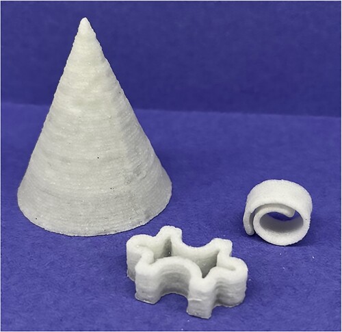
AM techniques have been tested at the laboratory level for solid propellent grains and other energetic materials with promising results. Studies by McClain et al. suggest that with the proper print controls and adjustments, propellants of extraordinarily high viscosity and solids loading may be printed at or near room temperature with the assistance of vibration [Citation112]. These printed propellants were found to have lower porosity than their cast counterparts with correspondingly favourable burn characteristics [Citation112]. Specifically targeting the print architecture, Wainwright et al. demonstrated that the energy release rates of thermites could be tuned by changing the print design. Although typical designs call for fully dense structures to maximise the reactive component per unit volume, they showed that specifically designed channels for convective gas transport can significantly increase the energy release rate [Citation223]. Thus, both DIW-prepared dense structures and lattice structures show promise for exceptional performance and tunability in propellants and other energetic materials.
Another benefit to DIW 3D printing that is promising for propellant applications is the ability to make parts with gradient compositions, enabling tailored burn rates. For example, by mixing HLS with Al (a fuel) and CuO (an oxidiser) at different ratios in an active mixing nozzle, a single printing process prepared a single part with both fast and slow burning regions, with the faster burning material moving ahead of the slower burning material, controlling the shape of the wavefront [Citation97]. Further, studies conducted by The Aerospace Corporation have tested hybrid propellant materials to show the feasibility and potential of tailored gains for improved regression rates and thrust-time profiles [Citation224–226].
5.3. Emerging applications
Although we only discussed two applications in detail, DIW of HLS has seen an uptake in the range of fields that employ the technique. summarises some of the important parameters used to successfully process and solidify a wide range of materials for different applications.
Table 2. Highlights of studies on DIW with high solid loadings that span a wide range of applications.
6. Challenges
Particle-laden materials cover important application spaces, ranging from biomedical to those for space exploration, and the ability to create complex shapes and functional gradients throughout a part shows great promise for increasing performance. As discussed throughout this review, there has been significant development in understanding what rheological properties are needed, how to extrude the very high viscosity inks and the challenges in post-processing. Within this, some excellent work has been done on how to design the ink formulations to meet those requirements.
Despite the tremendous customizability of DIW inks, the large material design space still presents significant knowledge gaps, leading to long lead times for formulation development. One of the main challenges is in generalising guidelines for formulation design, since the particle types and binders used in DIW differ greatly from one application space to another. Thus far, much of the formulation development focus has instead been on finding binder materials compatible with a given particle source that result in desirable rheology and solidification, while matching needed part properties. As demonstrated in this review, this approach works well for prototype printing demonstrations. However, scale-up and commercialisation are still largely unaddressed, due to remaining knowledge gaps. Therefore, advancing the field will require further investigations at different productions levels such as tailored particle-binder interactions, the mechanisms of particle aggregation, sedimentation and spatial distribution, and on ink microstructure deformation during solidification.
7. Future perspectives
Improving processability of various types of DIW ink containing high solid content has been the major driving focus of the literature in recent years. Despite this, few works target engineering the formulation materials themselves to improve the DIW printing process. Drawing inspiration from solution processing fields, such as coatings, and building upon the significant research done to develop polymers, surfactants and other additives that improve formulation processability is a promising avenue. For HLS this could include co-polymers that change the rheology, lubricants that tune friction between particles and surfactants that influence the air-solvent interface, among other designs. Similarly, in many powder handling processes, particle engineering has made great advances in improving flow and performance. Particle engineering could be used to design around challenges discussed throughout this article such as creating smooth, spherical particles that improve flow or coating particles to change UV absorption and reflectivity, with potential applications such as engineering Lunar regolith for concrete production. [Citation246] Targeted engineering of the materials that make up the HLS could usher in even more advanced materials and more predictable processing. Additionally, applying Quality-by-Design principles used in pharmaceutical process development, which emphasises systematic design of experiments and strong formulation and process understanding, can provide comprehensive understanding to speed up future materials development and enable scale-up processes.
As these new designs for high-solids materials begin to transition from research to production, ensuring robust processes and consistent product quality will also drive the future of the field. A growing focus in this space is on in-line monitoring and process optimisation. Having a printer system capable of learning process parameters for new inks through a series of test prints can provide the flexibility for handling new materials without significant start-up efforts. A recent study addressed this by using image processing on test prints and feeding key parameters into a machine learning algorithm to optimise the process and test whether the optimisation led to a desired result. The optimisation was done with the square wave print, enabling analysis of the start-stop behaviour, the line width consistency and a curving toolpath. They demonstrated that the ML-based optimised process was able to provide significant improvement in print quality over an unoptimised print and that this was translatable to a second printer at a different location [Citation247]. By using image analysis, or other similar rapid characterisation tools, such as inline IR or Raman monitoring for gradient compositions, paired with data analytics, programmes can be developed to cover a design space relevant to given applications wherein the training data set covers sufficient parameter space to allow for prediction and optimisation of process parameters for new ink formulations. Although many new research inks will fall outside of the parameter space, this is very helpful for commercial development, where ink formulations tend to be relatively similar from one product to another and can readily fall within the developed design space.
The field of using DIW additive manufacturing to prepare materials from formulations containing very high fractions of particles is at an exciting point, with good foundational knowledge enabling creative design and testing. While further work is needed to make this flexible printing method more broadly used, the challenges to overcome provide many appealing scientific and engineering questions, further motivating efforts in understanding and developing this manufacturing direction. The interdisciplinary nature of this development, from chemistry to mechanical engineering to process engineering to all the application specialists provides a rich landscape for innovative thinking and further developments that we haven't even dreamed of yet.
Disclosure statement
No potential conflict of interest was reported by the author(s).
Data availability statement
Data are available upon request.
Additional information
Funding
References
- DeLuca LT, Galfetti L. Burning of metallized composite solid rocket propellants: from micrometric to nanometric aluminum size. Proceedings of the Korean Society of Propulsion Engineers Conference; 2008 Mar 06–08; Gyeongju, Korea: The Korean Society of Propulsion Engineers.
- Ghassemi T, Shahroodi A, Ebrahimzadeh MH, et al. Current concepts in scaffolding for bone tissue engineering. Arch Bone Jt Surg. 2018;6(2):90–99.
- Barrett J. Powder metallurgy in aerospace applications. JOM. 1963;15(5):349–351. doi:10.1007/BF03378242
- Yang Y, Sigmund WM. A new approach to prepare highly loaded aqueous alumina suspensions with temperature sensitive rheological properties. J Eur Ceram Soc. 2003;23(2):253–261. doi:10.1016/S0955-2219(02)00179-6
- Liu Y, Lim J, Teoh S-H. Development of clinically relevant scaffolds for vascularised bone tissue engineering. Biotechnol Adv. 2013;31(5):688–705. doi:10.1016/j.biotechadv.2012.10.003
- Edrees H, Smith A, Hendry A. A rule-of-mixtures model for sintering of particle-reinforced ceramic-matrix composites. J Eur Ceram Soc. 1998;18(3):275–278. doi:10.1016/S0955-2219(97)00108-8
- Derby B, Reis N. Inkjet printing of highly loaded particulate suspensions. MRS Bull. 2003;28(11):815–818. doi:10.1557/mrs2003.230
- Blanco E, Hodgson DJ, Hermes M, et al. Conching chocolate is a prototypical transition from frictionally jammed solid to flowable suspension with maximal solid content. Proc Natl Acad Sci USA. 2019;116(21):10303–8. doi:10.1073/pnas.1901858116
- He J, Lee SS, Kalyon DM. Shear viscosity and wall slip behavior of dense suspensions of polydisperse particles. J Rheol. 2019;63(1):19–32. doi:10.1122/1.5053702
- Baule A, Mari R, Bo L, et al. Mean-field theory of random close packings of axisymmetric particles. Nat Commun. 2013;4:2194. doi:10.1038/ncomms3194
- Guan L, Fan J, Chan XY, et al. Continuous 3D printing of microstructured multifunctional materials. Additive Manufacturing. 2023;62:103373. doi:10.1016/j.addma.2022.103373
- Dee P, Tan S, Ferrand HL. Fabrication of microstructured calcium phosphate ceramics scaffolds by material extrusion-based 3D printing approach. Int J Bioprint. 2022;8(2):551. doi:10.18063/ijb.v8i2.551
- Su R, Chen J, Zhang X, et al. 3D-Printed micro/nano-scaled mechanical metamaterials: fundamentals, technologies, progress, applications, and challenges. Small. 2023;19(29):e2206391. doi:10.1002/smll.202206391
- Perez KB, Williams CB. Combining additive manufacturing and direct write for integrated electronics—a review. 24th International Solid Freeform Fabrication Symposium—An Additive Manufacturing Conference, SFF; 2013.
- Mason MS, Huang T, Landers RG, et al. Aqueous-based extrusion of high solids loading ceramic pastes: process modeling and control. J Mater Process Technol. 2009;209(6):2946–2957. doi:10.1016/j.jmatprotec.2008.07.004
- Li W, Ghazanfari A, Leu MC, et al. Methods of extrusion on demand for high solids loading ceramic paste in freeform extrusion fabrication. Solid Freeform Fabrication Symposium, Austin, TX; 2015.
- Desktop Metal. - Office friendly metal 3D printing 2020. Available from: https://www.desktopmetal.com/products/studio/.
- Dimension Inx. Available from: https://www.dimensioninx.com.
- ICON Technology. (2023). Available from: https://www.iconbuild.com/technology.
- Li W, Ghazanfari A, Leu MC, et al. Extrusion-on-demand methods for high solids loading ceramic paste in freeform extrusion fabrication. Virtual Phys Prototyp. 2017;12(3):193–205. doi:10.1080/17452759.2017.1312735
- Li M, Tang L, Landers RG, et al. Extrusion process modeling for aqueous-based ceramic pastes—part 2: experimental verification. J Manuf Sci Eng. 2013;135(5):051009.
- Wang W, Zhang L, Dong X, et al. Additive manufacturing of fiber reinforced ceramic matrix composites: advances, challenges, and prospects. Ceram Int. 2022;48(14):19542–19556. doi:10.1016/j.ceramint.2022.04.146
- Novich BE, Occhionero MA, Pober RL, inventors; Ceramics Process Systems Corp., assignee. Highly loaded, pourable suspensions of particulate materials. United States Patent patent 4,904,411. 1990 Februry 27.
- Teng WD, Edirisinghe MJ. Development of ceramic inks for direct continuous jet printing. J Am Ceram Soc. 1998;81(4):1033–1036. doi:10.1111/j.1151-2916.1998.tb02443.x
- Aral BK, Kalyon DM. Viscoelastic material functions of noncolloidal suspensions with spherical particles. J Rheol. 1997;41(3):599–620. doi:10.1122/1.550841
- Kalyon DM, Aktaş S. Factors affecting the rheology and processability of highly filled suspensions. Annu Rev Chem Biomol Eng. 2014;5:229–254. doi:10.1146/annurev-chembioeng-060713-040211
- Sweeney M, Campbell LL, Hanson J, et al. Characterizing the feasibility of processing wet granular materials to improve rheology for 3D printing. J Mater Sci. 2017;52(22):13040–13053. doi:10.1007/s10853-017-1404-z
- Rueschhoff L, Costakis W, Michie M, et al. Additive manufacturing of dense ceramic parts via direct Ink writing of aqueous alumina suspensions. Int J Appl Ceram Technol. 2016;13(5):821–830. doi:10.1111/ijac.12557
- An T, Hwang K-T, Kim J-H, et al. Extrusion-based 3D direct ink writing of NiZn-ferrite structures with viscoelastic ceramic suspension. Ceram Int. 2020;46(5):6469–6476. doi:10.1016/j.ceramint.2019.11.127
- He J, Lee SS, Kalyon DM. Shear viscosity and wall slip behavior of dense suspensions of polydisperse particles. Journal of Rheology. 2019;63(1):19–32.
- Campbell I, Marnot A, Ketcham M, et al. Direct ink write 3D printing of high solids loading bimodal distributions of particles. AIChE J. 2021;67(12):e17412. doi:10.1002/aic.17412
- Smay JE, Cesarano III J, Tuttle BA, et al. Piezoelectric properties of 3-X periodic Pb (Zr×Ti 1− x) O 3–polymer composites. J Appl Phys. 2002;92(10):6119–6127. doi:10.1063/1.1513202
- Costakis WJ, Rueschhoff LM, Diaz-Cano AI, et al. Additive manufacturing of boron carbide via continuous filament direct ink writing of aqueous ceramic suspensions. J Eur Ceram Soc. 2016;36(14):3249–3256. doi:10.1016/j.jeurceramsoc.2016.06.002
- Kaully T, Siegmann A, Shacham D. Rheology of highly filled natural CaCO3 composites. I. Effects of solid loading and particle size distribution on capillary rheometry. Polym Compos. 2007;28(4):512–523. doi:10.1002/pc.20308
- Corder RD, Chen YJ, Pibulchinda P, et al. Rheology of 3D printable ceramic suspensions: effects of non-adsorbing polymer on discontinuous shear thickening. Soft Matter. 2023;19(5):882–891. doi:10.1039/D2SM01396G
- Pospischil M, Zengerle K, Specht J, et al. Investigations of thick-film-paste rheology for dispensing applications. Energy Procedia. 2011;8:449–454. doi:10.1016/j.egypro.2011.06.164
- M’barki A, Bocquet L, Stevenson A. Linking rheology and printability for dense and strong ceramics by direct ink writing. Sci Rep. 2017;7(1):1–10. doi:10.1038/s41598-016-0028-x
- Li L, Lin Q, Tang M, et al. Advanced polymer designs for direct-ink-write 3D printing. Chem Eur J. 2019;25(46):10768–10781. doi:10.1002/chem.201900975
- Acosta M, Wiesner VL, Martinez CJ, et al. Effect of polyvinylpyrrolidone additions on the rheology of aqueous,: highly loaded alumina suspensions. J Am Ceram Soc. 2013;96(5):1372–1382. doi:10.1111/jace.12277
- Mezger T. The rheology handbook: For users of rotational and oscillatory rheometers. Vincentz network GmbH & Co KG, Hannover, Germany. 2006.
- Schwarze R, Gladkyy A, Uhlig F, et al. Rheology of weakly wetted granular materials: a comparison of experimental and numerical data. Granular Matter. 2013;15(4):455–465. doi:10.1007/s10035-013-0430-z
- Folayan JA, Anawe PAL, Abioye PO, et al. Selecting the most appropriate model for rheological characterization of synthetic based drilling mud. Int J Appl Eng Res. 2017;12(18):7614–7629.
- Malkin AY, Patlazhan S. Wall slip for complex liquids–phenomenon and its causes. Adv Colloid Interface Sci. 2018;257:42–57. doi:10.1016/j.cis.2018.05.008
- Moon JY, Dai S, Chang L, et al. The effect of sphere roughness on the rheology of concentrated suspensions. J Non-Newtonian Fluid Mech. 2015;223:233–239. doi:10.1016/j.jnnfm.2015.07.007
- Chen T, Sun A, Chu C, et al. Rheological behavior of titania ink and mechanical properties of titania ceramic structures by 3D direct ink writing using high solid loading titania ceramic ink. J Alloys Compd. 2019;783:321–328. doi:10.1016/j.jallcom.2018.12.334
- Rosental T, Magdassi S. A new approach to 3D printing dense ceramics by ceramic precursor binders. Adv Eng Mater. 2019;21(10):1–8. doi:10.1002/adem.201900604
- Smith PT, Basu A, Saha A, et al. Chemical modification and printability of shear-thinning hydrogel inks for direct-write 3D printing. Polymer. 2018;152:42–50. doi:10.1016/j.polymer.2018.01.070
- Worldwide MI. Whitepaper – a basic introduction to rheology shear flow. 2016. p. 1–20.
- Mezger TG. Applied Rheology. Anton Paar. 2014. p. 191.
- Sun Q, Yang Z, Cheng H, et al. Creation of three-dimensional structures by direct ink writing with kaolin suspensions. J Mater Chem C. 2018;6(42):11392–11400. doi:10.1039/C8TC03152E
- Nguyen DT, Meyers C, Yee TD, et al. 3D-printed transparent glass. Adv Mater. 2017;29(26):1–5. doi:10.1002/adma.201701181
- Barnes HA. Thixotropy—a review. J Non-Newtonian Fluid Mech. 1997;70(1-2):1–33. doi:10.1016/S0377-0257(97)00004-9
- Reynolds PA, Goodwin JW. Direct measurement of the translational diffusion coefficients of aggregated polystyrene latex particles. Colloids Surf. 1984;11(1-2):145–154. doi:10.1016/0166-6622(84)80243-7
- Perret D, Locat J, Martignoni P. Thixotropic behavior during shear of a fine-grained mud from eastern Canada. Eng Geol. 1996;43(1):31–44. doi:10.1016/0013-7952(96)00031-2
- Tixier N, Guibaud G, Baudu M. Towards a rheological parameter for activated sludge bulking characterisation. Enzyme Microb Technol. 2003;33(2-3):292–298. doi:10.1016/S0141-0229(03)00124-8
- Nan B, Gołębiewski P, Buczyński R, et al. Direct ink writing glass: a preliminary step for optical application. Materials (Basel). 2020;13(7):1–13.
- Eom Y, Kim F, Yang SE, et al. Rheological design of 3D printable all-inorganic inks using BiSbTe-based thermoelectric materials. J Rheol. 2019;63(2):291–304. doi:10.1122/1.5058078
- Zhu C, Smay JE. Thixotropic rheology of concentrated alumina colloidal gels for solid freeform fabrication. J Rheol. 2011;55(3):655–672. doi:10.1122/1.3573828
- Fennis S, Walraven J, Nijland T. Measuring the packing density to lower the cement content in concrete. Proceedings of the International FIB Symposium 2008 2008: Taylor & Francis Group.
- Mall-Gleissle SE, Gleissle W, McKinley GH, et al. The normal stress behaviour of suspensions with viscoelastic matrix fluids. Rheol Acta. 2002;41(1-2):61–76. doi:10.1007/s003970200006
- Weston JS, Chun J, Schenter G, et al. Connecting particle interactions to agglomerate morphology and rheology of boehmite nanocrystal suspensions. J Colloid Interface Sci. 2020;572:328–339. doi:10.1016/j.jcis.2020.03.109
- Marnot A, Dobbs A, Brettmann B. Material extrusion additive manufacturing of dense pastes consisting of macroscopic particles. MRS Commun. 2022;12(5):483–494. doi:10.1557/s43579-022-00209-1
- Krieger IM. Rheology of monodisperse latices. Adv Colloid Interface Sci. 1972;3(2):111–136. doi:10.1016/0001-8686(72)80001-0
- Smay JE, Cesarano J, Lewis JA. Colloidal inks for directed assembly of 3-D periodic structures. Langmuir. 2002;18(14):5429–5437. doi:10.1021/la0257135
- Mahaut F, Chateau X, Coussot P, et al. Yield stress and elastic modulus of suspensions of noncolloidal particles in yield stress fluids. J Rheol. 2008;52(1):287–313. doi:10.1122/1.2798234
- Feilden E, Blanca EG-T, Giuliani F, et al. Robocasting of structural ceramic parts with hydrogel inks. J Eur Ceram Soc. 2016;36(10):2525–2533. doi:10.1016/j.jeurceramsoc.2016.03.001
- Smay JE, Lewis JA. Solid free-form fabrication of 3-D ceramic structures. Ceram Composit Process Methods. 2012: 459–484. doi:10.1002/9781118176665.ch13
- Channell GM, Miller KT, Zukoski CF. Effects of microstructure on the compressive yield stress. AIChE J. 2000;46(1):72–78. doi:10.1002/aic.690460110
- Cumberland D, Crawford RJ. The packing of particles. Elsevier; 1987.
- McGeary R. Mechanical packing of spherical particles. J Am Ceram Soc. 1961;44(10):513–522. doi:10.1111/j.1151-2916.1961.tb13716.x
- Stickel JJ, Powell RL. Fluid mechanics and rheology of dense suspensions. Annu Rev Fluid Mech. 2005;37:129–149. doi:10.1146/annurev.fluid.36.050802.122132
- Van Kao S, Nielsen LE, Hill CT. Rheology of concentrated suspensions of spheres. I. effect of the liquid—solid interface. J Colloid Interface Sci. 1975;53(3):358–366. doi:10.1016/0021-9797(75)90051-X
- Woods H, Boddorff A, Ewaldz E, et al. Rheological considerations for binder development in direct ink writing of energetic materials. propellants, explosives. Pyrotechnics. 2020;45(1):26–35. doi:10.1002/prep.201900159
- Sigmund WM, Bell NS, Bergström L. Novel powder-processing methods for advanced ceramics. J Am Ceram Soc. 2000;83(7):1557–1574. doi:10.1111/j.1151-2916.2000.tb01432.x
- Doiphode ND, Huang T, Leu MC, et al. Freeze extrusion fabrication of 13-93 bioactive glass scaffolds for bone repair. J Mater Sci Mater Med. 2011;22(3):515–523. doi:10.1007/s10856-011-4236-4
- Leu MC, Deuser BK, Tang L, et al. Freeze-form extrusion fabrication of functionally graded materials. CIRP Ann. 2012;61(1):223–226. doi:10.1016/j.cirp.2012.03.050
- Liu L, Xiong Z, Yan Y, et al. Porous morphology: porosity, mechanical properties of poly(alpha-hydroxy acid)-tricalcium phosphate composite scaffolds fabricated by low-temperature deposition. J Biomed Mater Res A. 2007;82(3):618–629. doi:10.1002/jbm.a.31177
- Geisendorfer NR, Shah RN. Effect of polymer binder on the synthesis and properties of 3D-printable particle-based liquid materials and resulting structures. ACS Omega. 2019;4(7):12088–12097. doi:10.1021/acsomega.9b00090
- Siyawamwaya M, du Toit LC, Kumar P, et al. 3D printed, controlled release, tritherapeutic tablet matrix for advanced anti-HIV-1 drug delivery. Eur J Pharm Biopharm. 2019;138:99–110. doi:10.1016/j.ejpb.2018.04.007
- Reynolds JP, Rau DA, Williams CB, et al. A rheological method to predict printability of high solids content inks via ultraviolet-assisted material extrusion. Addit Manuf. 2023;75:103745. doi:10.1016/j.addma.2023.103753
- Seerden KA, Reis N, Evans JR, et al. Ink-jet printing of wax-based alumina suspensions. J Am Ceram Soc. 2001;84(11):2514–2520. doi:10.1111/j.1151-2916.2001.tb01045.x
- Reis N, Ainsley C, Derby B. Viscosity and acoustic behavior of ceramic suspensions optimized for phase-change ink-jet printing. J Am Ceram Soc. 2005;88(4):802–808. doi:10.1111/j.1551-2916.2005.00138.x
- Özkol E, Ebert J, Telle R. An experimental analysis of the influence of the ink properties on the drop formation for direct thermal inkjet printing of high solid content aqueous 3Y-TZP suspensions. J Eur Ceram Soc. 2010;30(7):1669–1678. doi:10.1016/j.jeurceramsoc.2010.01.004
- Özkol E, Wätjen AM, Bermejo R, et al. Mechanical characterisation of miniaturised direct inkjet printed 3Y-TZP specimens for microelectronic applications. J Eur Ceram Soc. 2010;30(15):3145–3152. doi:10.1016/j.jeurceramsoc.2010.07.016
- Jang S, Boddorff A, Jang DJ, et al. Effect of material extrusion process parameters on filament geometry and inter-filament voids in as-fabricated high solids loaded polymer composites. Additive Manufacturing. 2021;47:102313. doi:10.1016/j.addma.2021.102313
- Elsayed H, Rebesan P, Giacomello G, et al. Direct ink writing of porous titanium (Ti6Al4V) lattice structures. Materials Science and Engineering: C. 2019;103:109794. doi:10.1016/j.msec.2019.109794
- Eqtesadi S, Motealleh A, Miranda P, et al. A simple recipe for direct writing complex 45S5 Bioglass® 3D scaffolds. Mater Lett. 2013;93:68–71. doi:10.1016/j.matlet.2012.11.043
- Eqtesadi S, Motealleh A, Miranda P, et al. Robocasting of 45S5 bioactive glass scaffolds for bone tissue engineering. J Eur Ceram Soc. 2014;34(1):107–118. doi:10.1016/j.jeurceramsoc.2013.08.003
- Dellinger JG, Cesarano III J, Jamison RD. Robotic deposition of model hydroxyapatite scaffolds with multiple architectures and multiscale porosity for bone tissue engineering. J Biomed Mater Res A. 2007;82(2):383–394.
- Roohani-Esfahani SI, Newman P, Zreiqat H. Design and fabrication of 3D printed scaffolds with a mechanical strength comparable to cortical bone to repair large bone defects. Sci Rep. 2016;6:19468. doi:10.1038/srep19468
- Simon JL, Michna S, Lewis JA, et al. In vivo bone response to 3D periodic hydroxyapatite scaffolds assembled by direct ink writing. J Biomed Mater Res A. 2007;83(3):747–758.
- Sun L, Parker ST, Syoji D, et al. Direct-write assembly of 3D silk/hydroxyapatite scaffolds for bone co-cultures. Adv Healthcare Mater. 2012;1(6):729–735. doi:10.1002/adhm.201200057
- Studart AR. Additive manufacturing of biologically-inspired materials. Chem Soc Rev. 2016;45(2):359–376. doi:10.1039/C5CS00836K
- Lewis JA, Smay JE, Stuecker J, et al. Direct Ink writing of three-dimensional ceramic structures. J Am Ceram Soc. 2006;89(12):3599–3609. doi:10.1111/j.1551-2916.2006.01382.x
- Minas C, Carnelli D, Tervoort E, et al. 3D printing of emulsions and foams into hierarchical porous ceramics. Adv Mater. 2016;28(45):9993–9999. doi:10.1002/adma.201603390
- Tang D, Hao L, Li Y, et al. Dual gradient direct ink writing for formation of kaolinite ceramic functionally graded materials. J Alloys Compd. 2020;814:152275. doi:10.1016/j.jallcom.2019.152275
- Golobic AM, Durban MD, Fisher SE, et al. Active mixing of reactive materials for 3D printing. Adv Eng Mater. 2019;21(8):1900147. doi:10.1002/adem.201900147
- Ortega JM, Golobic M, Sain JD, et al. Active mixing of disparate inks for multimaterial 3D printing. Advanced Materials Technologies. 2019;4(7):1800717. doi:10.1002/admt.201800717
- Guo W, Jiang Z, Zhong H, et al. 3D printing of multifunctional gradient bone scaffolds with programmable component distribution and hierarchical pore structure. Compos Part A Appl Sci Manuf. 2023;166:107361.
- Motealleh A, Eqtesadi S, Perera FH, et al. Reinforcing 13–93 bioglass scaffolds fabricated by robocasting and pressureless spark plasma sintering with graphene oxide. J Mech Behav Biomed Mater. 2019;97:108–116. doi:10.1016/j.jmbbm.2019.05.016
- Michna S, Wu W, Lewis JA. Concentrated hydroxyapatite inks for direct-write assembly of 3-D periodic scaffolds. Biomaterials. 2005;26(28):5632–5639. doi:10.1016/j.biomaterials.2005.02.040
- Miranda P, Saiz E, Gryn K, et al. Sintering and robocasting of β-tricalcium phosphate scaffolds for orthopaedic applications. Acta Biomater. 2006;2(4):457–466. doi:10.1016/j.actbio.2006.02.004
- Faes M, Valkenaers H, Vogeler F, et al. Extrusion-based 3D printing of ceramic components. Procedia CIRP. 2015;28:76–81. doi:10.1016/j.procir.2015.04.028
- Cai K, Román-Manso B, Smay JE, et al. Geometrically complex silicon carbide structures fabricated by robocasting. J Am Ceram Soc. 2012;95(8):2660–2666. doi:10.1111/j.1551-2916.2012.05276.x
- Li W, Ghazanfari A, McMillen D, et al. Characterization of zirconia specimens fabricated by ceramic on-demand extrusion. Ceram Int. 2018;44(11):12245–12252. doi:10.1016/j.ceramint.2018.04.008
- Li Q, Lewis JA. Nanoparticle inks for directed assembly of three-dimensional periodic structures. Adv Mater. 2003;15(19):1639–1643. doi:10.1002/adma.200305413
- Glymond D, Vandeperre LJ. Robocasting of MgO-doped alumina using alginic acid slurries. J Am Ceram Soc. 2018;101(8):3309–3316. doi:10.1111/jace.15509
- Masuda H, Ohta Y, Kitayama M. Additive manufacturing of SiC ceramics with complicated shapes using the FDM type 3D-printer. J Mater Sci Chem Eng. 2019;07(02):1–12. doi:10.4236/msce.2019.72001
- Huang T, Hilmas GE, Fahrenholtz WG, et al. Dispersion of zirconium diboride in an aqueous: high-solids paste. Int J Appl Ceram Technol. 2007;4(5):470–479. doi:10.1111/j.1744-7402.2007.02157.x
- Stuecker JN, Cesarano J, Hirschfeld DA. Control of the viscous behavior of highly concentrated mullite suspensions for robocasting. J Mater Process Technol. 2003;142(2):318–325. doi:10.1016/S0924-0136(03)00586-7
- Gunduz I, McClain M, Cattani P, et al. 3D printing of extremely viscous materials using ultrasonic vibrations. Addit Manuf. 2018;22:98–103. doi:10.1016/j.addma.2018.04.029
- McClain M, Gunduz I, Son S. Additive manufacturing of ammonium perchlorate composite propellant with high solids loadings. Proc Combust Inst. 2019;37(3):3135–3142. doi:10.1016/j.proci.2018.05.052
- Dunju W, Changping G, Ruihao W, et al. Additive manufacturing and combustion performance of CL-20 composites. J Mater Sci. 2019;55(7):2836–2845. doi:10.1007/s10853-019-04209-w
- Tang S, Yang L, Li G, et al. 3D printing of highly-loaded slurries via layered extrusion forming: parameters optimization and control. Addit Manuf. 2019;28:546–553. doi:10.1016/j.addma.2019.05.034
- Schlordt T, Keppner F, Travitzky N, et al. Robocasting of alumina lattice truss structures. J Ceramic Sci Technol. 2012;3(2):81–87.
- Hong S, Sanchez C, Du H, et al. Fabrication of 3D printed metal structures by use of high-viscosity cu paste and a screw extruder. J Electron Mater. 2015;44(3):836–841. doi:10.1007/s11664-014-3601-8
- Bourret J, El Younsi I, Bienia M, et al. Micro extrusion of innovative alumina pastes based on aqueous solvent and eco-friendly binder. J Eur Ceram Soc. 2018;38(7):2802–2807. doi:10.1016/j.jeurceramsoc.2018.02.018
- Held A, Puchas G, Müller F, et al. Direct ink writing of water-based C–SiC pastes for the manufacturing of SiSiC components. Open Ceramics. 2021;5:100054.
- Lengauer W, Duretek I, Fürst M, et al. Fabrication and properties of extrusion-based 3D-printed hardmetal and cermet components. Int J Refract Met Hard Mater. 2019;82:141–149. doi:10.1016/j.ijrmhm.2019.04.011
- Yang L, Zeng X, Ditta A, et al. Preliminary 3D printing of large inclined-shaped alumina ceramic parts by direct ink writing. Journal of Advanced Ceramics. 2020;9:312–319. doi:10.1007/s40145-020-0369-6
- Jianping L, Guiling D. Technology development and basic theory study of fluid dispensing-a review. Proceedings of the Sixth IEEE CPMT Conference on High Density Microsystem Design and Packaging and Component Failure Analysis (HDP’04); 2004 Jul 03–03; Shanghai, China: IEEE.
- Corporation N. 741 V needle valve system for precise: consistent fluid control 2010. Available from: https://pdf.directindustry.com/pdf/nordson-efd/741v-needle-valve/35688-657310.html.
- Balani SB, Ghaffar SH, Chougan M, et al. Processes and materials used for direct writing technologies: A review. Results in Engineering. 2021;11:100257. doi:10.1016/j.rineng.2021.100257
- Lewis JA. Direct ink writing of 3D functional materials. Adv Funct Mater. 2006;16(17):2193–2204. doi:10.1002/adfm.200600434
- Udofia EN, Zhou W. A guiding framework for microextrusion additive manufacturing. J Manuf Sci Eng. 2019;141(5):050801. doi:10.1115/1.4042607
- Benbow J. The dependence of output rate on die shape during catalyst extrusion. Chem Eng Sci. 1971;26(9):1467–1473. doi:10.1016/0009-2509(71)80066-0
- Benbow J, Bridgwater J. Paste flow and extrusion. 1993.
- Franco J, Hunger P, Launey ME, et al. Direct write assembly of calcium phosphate scaffolds using a water-based hydrogel. Acta Biomater. 2010;6(1):218–228. doi:10.1016/j.actbio.2009.06.031
- Morissette SL, Lewis JA, Clem PG, et al. Direct-Write fabrication of Pb (Nb,: Zr, Ti) O3 devices: influence of paste rheology on print morphology and component properties. J Am Ceram Soc. 2001;84(11):2462–2468. doi:10.1111/j.1151-2916.2001.tb01036.x
- Shen A, Peng X, Bailey CP, et al. 3D printing of polymer-bonded magnets from highly concentrated,: plate-like particle suspensions. Mater Des. 2019;183:108133. doi:10.1016/j.matdes.2019.108133
- Fu Z, Freihart M, Wahl L, et al. Micro-and macroscopic design of alumina ceramics by robocasting. J Eur Ceram Soc. 2017;37(9):3115–3124. doi:10.1016/j.jeurceramsoc.2017.03.052
- Ren X, Shao H, Lin T, et al. 3D gel-printing—An additive manufacturing method for producing complex shape parts. Mater Des. 2016;101:80–87. doi:10.1016/j.matdes.2016.03.152
- Morissette SL, Lewis JA, Cesarano J, et al. Solid freeform fabrication of aqueous alumina–poly (vinyl alcohol) gelcasting suspensions. J Am Ceram Soc. 2000;83(10):2409–2416. doi:10.1111/j.1151-2916.2000.tb01569.x
- Thornton AS. Freeze-form extrusion fabrication of boron carbide. Missouri University of Science and Technology; 2015.
- Chan SSL, Pennings RM, Edwards L, et al. 3D printing of clay for decorative architectural applications: effect of solids volume fraction on rheology and printability. Additive Manufacturing. 2020;35:101335.
- Yilmazer U, Gogos CG, Kalyon DM. Mat formation and unstable flows of highly filled suspensions in capillaries and continuous processors. Polym Compos. 1989;10(4):242–248. doi:10.1002/pc.750100406
- Yaras DMK P, Yilmazer U. Flow instabilities in capillary flow of concentrated suspensions. Rheol Acta. 1994;33:48–59. doi:10.1007/BF00453463
- Liu H, Liu J, Leu MC, et al. Factors influencing paste extrusion pressure and liquid content of extrudate in freeze-form extrusion fabrication. Int J Adv Manuf Technol. 2012;67(1-4):899–906. doi:10.1007/s00170-012-4534-0
- Ji H, Zhao J, Chen J, et al. A novel experimental approach to quantitatively evaluate the printability of inks in 3D printing using two criteria. Addit Manuf. 2022;55:102846.
- Perrot A, Lanos C, Estellé P, et al. Ram extrusion force for a frictional plastic material: model prediction and application to cement paste. Rheol Acta. 2006;45(4):457–467. doi:10.1007/s00397-005-0074-y
- Guo C-F, Zhang M, Bhandari B. A comparative study between syringe-based and screw-based 3D food printers by computational simulation. Comput Electron Agric. 2019;162:397–404. doi:10.1016/j.compag.2019.04.032
- Perez KB, Williams CB. Characterization of in-situ conductive paste extrusion on polyjet substrates. International solid freeform fabrication symposium, Austin (TX); 2014.
- Bonada J, Xuriguera E, Calvo L, et al. Analysis of printing parameters for metal additive manufactured parts through direct Ink writing process. Procedia Manuf. 2019;41:666–673. doi:10.1016/j.promfg.2019.09.056
- Yuk H, Zhao X. A new 3D printing strategy by harnessing deformation,: instability, and fracture of viscoelastic inks. Adv Mater. 2018;30(6):1704028. doi:10.1002/adma.201704028
- Shao H, He J, Lin T, et al. 3D gel-printing of hydroxyapatite scaffold for bone tissue engineering. Ceram Int. 2019;45(1):1163–1170. doi:10.1016/j.ceramint.2018.09.300
- Ghazanfari A, Li W, Leu MC, et al. A novel freeform extrusion fabrication process for producing solid ceramic components with uniform layered radiation drying. Addit Manuf. 2017;15:102–112. doi:10.1016/j.addma.2017.04.001
- Udofia EN, Zhou W. Microextrusion based 3D printing—A review. Proceedings of the 29th Annual International Solid Freeform Fabrication Symposium—An Additive Manufacturing Conference, Austin, TX, USA; 2018.
- de Hazan Y, Thänert M, Trunec M, et al. Robotic deposition of 3d nanocomposite and ceramic fiber architectures via UV curable colloidal inks. J Eur Ceram Soc. 2012;32(6):1187–1198. doi:10.1016/j.jeurceramsoc.2011.12.007
- Finke S, Feenstra F. Solid freeform fabrication by extrusion and deposition of semi-solid alloys. J Mater Sci. 2002;37(15):3101–3106. doi:10.1023/A:1016137723481
- Arango MT, Abidakun O, Korakakis D, et al. Tuning the crystalline microstructure of Al-doped ZnO using direct ink writing. Flex Print Electron. 2017;2(3):035006. doi:10.1088/2058-8585/aa8801
- Vozzi G, Previti A, De Rossi D, et al. Microsyringe-based deposition of two-dimensional and three-dimensional polymer scaffolds with a well-defined geometry for application to tissue engineering. Tissue Eng. 2002;8(6):1089–1098. doi:10.1089/107632702320934182
- Wang J, Shaw LL. Rheological and extrusion behavior of dental porcelain slurries for rapid prototyping applications. Mater Sci Eng A. 2005;397(1-2):314–321. doi:10.1016/j.msea.2005.02.045
- Wang W, Gao X, Zhang L, et al. Large-scale material extrusion-based additive manufacturing of short carbon fibre-reinforced silicon carbide ceramic matrix composite preforms. Virtual Phys Prototyp. 2023;18(1):e2245801. doi:10.1080/17452759.2020.1823116
- Li JP, de Wijn JR, Van Blitterswijk CA, et al. Porous Ti6Al4V scaffold directly fabricating by rapid prototyping: preparation and in vitro experiment. Biomaterials. 2006;27(8):1223–1235. doi:10.1016/j.biomaterials.2005.08.033
- Bagheri A, Jin J. Photopolymerization in 3D printing. ACS Appl Polym Mater. 2019;1(4):593–611. doi:10.1021/acsapm.8b00165
- Pandey R. Photopolymers in 3D printing applications. 2014. https://www.theseus.fi/handle/10024/80083
- Hinczewski C, Corbel S, Chartier T. Ceramic suspensions suitable for stereolithography. J Eur Ceram Soc. 1998;18(6):583–590. doi:10.1016/S0955-2219(97)00186-6
- Bennett J. Measuring UV curing parameters of commercial photopolymers used in additive manufacturing. Additive Manufacturing. 2017;18:203–212. doi:10.1016/j.addma.2017.10.009
- Tomeckova V, Halloran JW. Critical energy for photopolymerization of ceramic suspensions in acrylate monomers. J Eur Ceram Soc. 2010;30(16):3273–3282. doi:10.1016/j.jeurceramsoc.2010.08.003
- Berrocal E, Sedarsky DL, Paciaroni ME, et al. Laser light scattering in turbid media part I: experimental and simulated results for the spatial intensity distribution. Opt Express. 2007;15(17):10649–10665. doi:10.1364/OE.15.010649
- Baker ET, Lavelle JW. The effect of particle size on the light attenuation coefficient of natural suspensions. J Geophys Res. 1984;89(C5):8197–8203. doi:10.1029/JC089iC05p08197
- Griffith ML, Halloran JW. Scattering of ultraviolet radiation in turbid suspensions. J Appl Phys. 1997;81(6):2538–2546. doi:10.1063/1.364311
- Gentry SP, Halloran JW. Depth and width of cured lines in photopolymerizable ceramic suspensions. J Eur Ceram Soc. 2013;33(10):1981–1988. doi:10.1016/j.jeurceramsoc.2013.02.033
- Chen Z, Li J, Liu C, et al. Preparation of high solid loading and low viscosity ceramic slurries for photopolymerization-based 3D printing. Ceram Int. 2019;45(9):11549–11557. doi:10.1016/j.ceramint.2019.03.024
- Halloran JW. Ceramic stereolithography: additive manufacturing for ceramics by photopolymerization. Annu Rev Mater Res. 2016;46:19–40. doi:10.1146/annurev-matsci-070115-031841
- Mie G. Contributions to the optics of turbid media,: particularly of colloidal metal solutions. Contribut Optics Turbid Media. 1976;25(3):377–445.
- Wu K, Seefeldt K, Solomon M, et al. Prediction of ceramic stereolithography resin sensitivity from theory and measurement of diffusive photon transport. J Appl Phys. 2005;98(2):024902. doi:10.1063/1.1980531
- Garg R, Prud’homme RK, Aksay IA, et al. Optical transmission in highly concentrated dispersions. JOSA A. 1998;15(4):932–935. doi:10.1364/JOSAA.15.000932
- Tomeckova V, Halloran JW. Predictive models for the photopolymerization of ceramic suspensions. J Eur Ceram Soc. 2010;30(14):2833–2840. doi:10.1016/j.jeurceramsoc.2010.01.027
- Zakeri S, Vippola M, Levänen E. A comprehensive review of the photopolymerization of ceramic resins used in stereolithography. Additive Manufacturing. 2020;35:101177. doi:10.1016/j.addma.2020.101177
- Jang JH, Wang S, Pilgrim SM, et al. Preparation and characterization of barium titanate suspensions for stereolithography. J Am Ceram Soc. 2004;83(7):1804–1806. doi:10.1111/j.1151-2916.2000.tb01467.x
- McClain MS, Afriat A, Rhoads JF, et al. Development and characterization of a photopolymeric binder for additively manufactured composite solid propellant using vibration assisted printing. propellants,: explosives. Pyrotechnics. 2020;45(6):853–863. doi:10.1002/prep.201900387
- Peng E, Zhang D, Ding J. Ceramic robocasting: recent achievements,: potential, and future developments. Adv Mater. 2018;30(47):1802404. doi:10.1002/adma.201802404
- Ahmet Nebioglu JAL, Khudyakov IV. New UV-curable high refractive index oligomers. Indust Eng Chem Res. 2008;47:2155–2159. doi:10.1021/ie071443f
- Altun AA, Ertl F, Marechal M, et al. Additive manufacturing of lunar regolith structures. Open Ceramics. 2021;5. doi:10.1016/j.oceram.2021.100058
- Yu T, Zhang Z, Liu Q, et al. Extrusion-based additive manufacturing of yttria-partially-stabilized zirconia ceramics. Ceram Int. 2020;46(4):5020–5027. doi:10.1016/j.ceramint.2019.10.245
- Jakus AE, Rutz AL, Jordan SW, et al. Hyperelastic “bone”: A highly versatile, growth factor–free, osteoregenerative, scalable, and surgically friendly biomaterial. Sci Transl Med. 2016;8(358):358ra127–358ra127. doi:10.1126/scitranslmed.aaf7704
- Cesarano III J, King BH, Denham HB. Recent developments in robocasting of ceramics and multimaterial deposition. Sandia National Labs., Albuquerque, NM (United States); 1998.
- Blanco E, Hodgson DJ, Hermes M, et al. Conching chocolate is a prototypical transition from frictionally jammed solid to flowable suspension with maximal solid content. Proc Natl Acad Sci U S A. 2019;116(21):10303–8. doi:10.1073/pnas.1901858116
- Evans M, Caldwell J. Evaluation of two different metabolic hypotheses for dichloromethane toxicity using physiologically based pharmacokinetic modeling for in vivo inhalation gas uptake data exposure in female B6C3F1 mice. Toxicol Appl Pharmacol. 2010;244(3):280–290. doi:10.1016/j.taap.2010.01.018
- Wilt JK, Gilmer D, Kim S, et al. Direct ink writing techniques for in situ gelation and solidification. MRS Commun. 2021;11:1–16.
- Sun K, Wei TS, Ahn BY, et al. 3D printing of interdigitated Li-Ion microbattery architectures. Adv Mater. 2013;25(33):4539–4543. doi:10.1002/adma.201301036
- Hodaei A, Akhlaghi O, Khani N, et al. Single additive enables 3D printing of highly loaded iron oxide suspensions. ACS Appl Mater Interfaces. 2018;10(11):9873–9881. doi:10.1021/acsami.8b00551
- Sanchez LC, Beatrice CAG, Lotti C, et al. Rheological approach for an additive manufacturing printer based on material extrusion. Int J Adv Manufact Technol. 2019;105(5):2403–2414. doi:10.1007/s00170-019-04376-9
- Croll S. Drying of latex paint. J Coatings Technologies. 1986;58(734):41–49.
- Zhou J, Man X, Jiang Y, et al. Structure formation in soft-matter solutions induced by solvent evaporation. Adv Mater. 2017;29(45):1703769.
- Cusola O, Kivisto S, Vierros S, et al. Particulate coatings via evaporation-induced self-assembly of polydisperse colloidal lignin on solid interfaces. Langmuir. 2018;34(20):5759–5771. doi:10.1021/acs.langmuir.8b00650
- Howard MP, Nikoubashman A, Panagiotopoulos AZ. Stratification dynamics in drying colloidal mixtures. Langmuir. 2017;33(15):3685–3693. doi:10.1021/acs.langmuir.7b00543
- Kim S, Hyun K, Struth B, et al. Structural development of nanoparticle dispersion during drying in polymer nanocomposite films. Macromolecules. 2016;49(23):9068–9079. doi:10.1021/acs.macromol.6b01939
- Abdeljawad F, Bolintineanu DS, Cook A, et al. Sintering processes in direct ink write additive manufacturing: A mesoscopic modeling approach. Acta Mater. 2019;169:60–75. doi:10.1016/j.actamat.2019.01.011
- Enneti RK, Park SJ, German RM. Atre SV. thermal debinding process in particulate materials processing. Mater Manuf Processes. 2012;27(2):103–118. doi:10.1080/10426914.2011.560233
- Aggarwal G, Park S-J, Smid I, et al. Master decomposition curve for binders used in powder injection molding. Metallurgical and Materials Transactions A. 2007;38(3):606–614. doi:10.1007/s11661-007-9102-0
- Yeh TS, Sacks MD. Effect of particle size distribution on the sintering of alumina. J Am Ceram Soc. 1988;71(12):C-484-C-7.
- Yan X, Wang C, Xiong W, et al. Thermal debinding mass transfer mechanism and dynamics of copper green parts fabricated by an innovative 3D printing method. RSC Adv. 2018;8(19):10355–10360. doi:10.1039/C7RA13149F
- Ren L, Zhou X, Song Z, et al. Process parameter optimization of extrusion-based 3D metal printing utilizing PW–LDPE–SA binder system. Materials (Basel). 2017;10(3):305. doi:10.3390/ma10030305
- Lieberwirth C, Harder A, Seitz H. Extrusion based additive manufacturing of metal parts. J Mech Eng Automat. 2017;7:79–83.
- Li H, Liu Y, Liu Y, et al. Effects of solvent debinding on the microstructure and properties of 3D-printed alumina ceramics. ACS Omega. 2020;5(42):27455–27462. doi:10.1021/acsomega.0c03944
- Justino JG, De Resende L, Fredel MC, et al. Powder injection molding: A comparison of two debinding procedures based on solvent extraction. Materials science forum; 1999: Trans Tech Publ.
- Yang W-W, Yang K-Y, Wang M-C, et al. Solvent debinding mechanism for alumina injection molded compacts with water-soluble binders. Ceram Int. 2003;29(7):745–756. doi:10.1016/S0272-8842(02)00226-2
- Tsai D-S, Chen W-W. Solvent debinding kinetics of alumina green bodies by powder injection molding. Ceram Int. 1995;21(4):257–264. doi:10.1016/0272-8842(95)99791-9
- Rak ZS. New trends in powder injection moulding. Powder Metall Met Ceram. 1999;38(3-4):126–132. doi:10.1007/BF02676037
- Lotfizarei Z, Mostafapour A, Barari A, et al. Overview of debinding methods for parts manufactured using powder material extrusion. Additive Manufacturing. 2023;61:103335. doi:10.1016/j.addma.2022.103335
- Gonzalez-Gutierrez J, Cano S, Schuschnigg S, et al. Additive manufacturing of metallic and ceramic components by the material extrusion of highly-filled polymers: A review and future perspectives. Materials (Basel. 2018;11(5):840. doi:10.3390/ma11050840
- Woodthorpe MJE J, Evans JRG. Properties of ceramic injection moulding formulations. J Mater Sci. 1989;24:1038–1048. doi:10.1007/BF01148795
- Cima MJ, Dudziak M, Lewis JA. Observation of poly{vinyl butyral}-dibutyl phthalate binder capillary migration. J Am Ceram Soc. 1989;72(6):1087–1090. doi:10.1111/j.1151-2916.1989.tb06280.x
- Hwang KS, Hsieh YM. Comparative study of pore structure evolution during solvent and thermal debinding of powder injection molded parts. Metallurg Mater Transact A. 1996;27:245–253.
- Song J, Evans J, Edirisinghe M, et al. Optimization of heating schedules in pyrolytic binder removal from ceramic moldings. J Mater Res. 2000;15(2):449–457. doi:10.1557/JMR.2000.0068
- Li H, Liu Y, Liu Y, et al. Effect of debinding temperature under an argon atmosphere on the microstructure and properties of 3D-printed alumina ceramics. Mater Charact. 2020;168:110548. doi:10.1016/j.matchar.2020.110548
- Dou R, Tang WZ, Wang L, et al. Sintering of lunar regolith structures fabricated via digital light processing. Ceram Int. 2019;45(14):17210–5. doi:10.1016/j.ceramint.2019.05.276
- Brown JL, Laurencin CT. Bone tissue engineering. In Biomaterials Science. 4th ed. Elsevier; 2020. p. 1373–1388.
- Langer R, Vacanti J. Tissue engineering. Science. 1993;260(5110):920–926. doi:10.1126/science.8493529
- Athanasiou K, Zhu C-F, Lanctot D, et al. Fundamentals of biomechanics in tissue engineering of bone. Tissue Eng. 2000;6(4):361–381. doi:10.1089/107632700418083
- Bose S, Vahabzadeh S, Bandyopadhyay A. Bone tissue engineering using 3D printing. Mater Today. 2013;16(12):496–504. doi:10.1016/j.mattod.2013.11.017
- Smith BT, Bittner SM, Watson E, et al. Multimaterial dual gradient three-dimensional printing for osteogenic differentiation and spatial segregation. Tissue Eng Part A. 2020;26(5-6):239–252. doi:10.1089/ten.tea.2019.0204
- Zeller B. Solid propellant grain design. In: Davenas A, editor. Solid rocket propulsion technology. New York: Elsevier; 1993. p. 35–84.
- Vandenkerckhove JA. Recent advances in solid propellant grain design. ARS Journal. 1959;29(7):483–491. doi:10.2514/8.4810
- Muthiah R, Krishnamurthy V, Gupta B. Rheology of HTPB propellant. I. effect of solid loading: oxidizer particle size, and aluminum content. J Appl Polym Sci. 1992;44(11):2043–2052.
- Klager K, Rogers C, Smith P. Rheology of composite solid propellants during motor casting. Modern propellants and explosives technology; 1978.
- Babuk V, Vassiliev V, Sviridov V. Propellant formulation factors and metal agglomeration in combustion of aluminized solid rocket propellant. Combust Sci Technol. 2001;163(1):261–289. doi:10.1080/00102200108952159
- Klager K, Wrightson JM., Erigem AC. Mechanics and chemistry of solid propellants. London: Adlard TD; 1967.
- Hendel FJ. Review of solid propellants for space exploration. NASA Technical Memorandum. 1965(33-254).
- Nagamachi MY, Oliveira JIS, Kawamoto AM, et al. ADN-The new oxidizer around the corner for an environmentally friendly smokeless propellant. J Aerospace Technol Manag. 2009;1(2):153–160. doi:10.5028/jatm.2009.0102153160
- Wainwright ER, Sullivan KT, Grapes MD. Designer direct Ink write 3D-printed thermites with tunable energy release rates. Adv Eng Mater. 2019;22(6). doi:10.1002/adem.202070026
- Armold D, Boyer JE, Kuo K, et al. Test of hybrid rocket fuel grains with swirl patterns fabricated using rapid prototyping technology. 49th AIAA/ASME/SAE/ASEE Joint PropulsionConference2013. p. 4141.
- Fuller J, Ehrlich D, Lu P, et al. Advantages of rapid prototyping for hybrid rocket motor fuel grain fabrication. 47th AIAA/ASME/SAE/ASEE Joint Propulsion Conference & Exhibit; 2011.
- Whitmore SA, Walker SD, Merkley DP, et al. High regression rate hybrid rocket fuel grains with helical port structures. J Propul Power. 2015;31(6):1727–1738. doi:10.2514/1.B35615
- Nommeots-Nomm A, Lee PD, Jones JR. Direct ink writing of highly bioactive glasses. J Eur Ceram Soc. 2018;38(3):837–844. doi:10.1016/j.jeurceramsoc.2017.08.006
- Ben-Arfa BAE, Neto S, Miranda Salvado IM, et al. Robocasting of Cu(2+) & La(3+) doped sol-gel glass scaffolds with greatly enhanced mechanical properties: compressive strength up to 14 MPa. Acta Biomater. 2019;87:265–272. doi:10.1016/j.actbio.2019.01.048
- Yang H, Yang S, Chi X, et al. Fine ceramic lattices prepared by extrusion freeforming. J Biomed Mater Res B Appl Biomater. 2006;79(1):116–121.
- Schlordt T, Schwanke S, Keppner F, et al. Robocasting of alumina hollow filament lattice structures. J Eur Ceram Soc. 2013;33(15-16):3243–3248. doi:10.1016/j.jeurceramsoc.2013.06.001
- Román-Manso B, De Pablos A, Belmonte M, et al. Microstructural designs of spark-plasma sintered silicon carbide ceramic scaffolds. Bol Soc Esp Ceram Vidr. 2014;53(2):93–100. doi:10.3989/cyv.132014
- Moini M, Olek J, Magee B, et al. Additive manufacturing and characterization of architectured cement-based materials via X-ray micro-computed tomography. RILEM International Conference on Concrete and Digital Fabrication; 2018: Springer.
- Huang T, Mason MS, Hilmas GE, et al. Freeze-form extrusion fabrication of ceramic parts. Virtual Phys Prototyp. 2006;1(2):93–100. doi:10.1080/17452750600649609
- Ghazanfari A, Li W, Leu M, et al. Mechanical characterization of parts produced by ceramic on-demand extrusion process. Int J Appl Ceram Technol. 2017;14(3):486–494. doi:10.1111/ijac.12665
- Yang L, Tang S, Li G, et al. Layered extrusion forming of complex ceramic structures using starch as removable support. Ceram Int. 2019;45(17):21843–21850. doi:10.1016/j.ceramint.2019.07.193
- Rao RB, Krafcik KL, Morales AM, et al. Microfabricated deposition nozzles for direct-write assembly of three-dimensional periodic structures. Adv Mater. 2005;17(3):289–293. doi:10.1002/adma.200400514
- San Marchi C, Kouzeli M, Rao R, et al. Alumina–aluminum interpenetrating-phase composites with three-dimensional periodic architecture. Scr Mater. 2003;49(9):861–866. doi:10.1016/S1359-6462(03)00441-X
- Scheithauer U, Schwarzer E, Richter HJ, et al. Thermoplastic 3D printing—an additive manufacturing method for producing dense ceramics. Int J Appl Ceram Technol. 2015;12(1):26–31. doi:10.1111/ijac.12306
- Lee Y, Lu X, Hao Y, et al. Rapid prototyping of ceramic millimeterwave metamaterials: simulations and experiments. Microw Opt Technol Lett. 2007;49(9):2090–2093. doi:10.1002/mop.22697
- Eqtesadi S, Motealleh A, Perera FH, et al. Fabricating geometrically-complex B4C ceramic components by robocasting and pressureless spark plasma sintering. Scr Mater. 2018;145:14–18. doi:10.1016/j.scriptamat.2017.10.001
- Nadkarni SS, Smay JE. Concentrated barium titanate colloidal gels prepared by bridging flocculation for Use in solid freeform fabrication. J Am Ceram Soc. 2006;89(1):96–103. doi:10.1111/j.1551-2916.2005.00646.x
- Smay JE, Gratson GM, Shepherd RF, Cesarano III J, Lewis JA. Directed colloidal assembly of 3D periodic structures. Adv Mater. 2002;14(18):1279–1283. doi:10.1002/1521-4095(20020916)14:18<1279::AID-ADMA1279>3.0.CO;2-A
- Zhang X, Guo Z, Chen C, et al. Additive manufacturing of WC-20Co components by 3D gel-printing. Int J Refract Met Hard Mater. 2018;70:215–223. doi:10.1016/j.ijrmhm.2017.10.005
- Tubío CR, Guitián F, Gil A. Fabrication of ZnO periodic structures by 3D printing. J Eur Ceram Soc. 2016;36(14):3409–3415. doi:10.1016/j.jeurceramsoc.2016.05.025
- Abid Hasan Rafi ML, Anthony V, Basler G, et al. Ceramic on-demand extrusion of ZrB2-SiC microchannels for ultra high-temperature compact heat exchanger. Solid freeform fabrication 2022: Proceedings of the 33rd Annual International Solid Freeform Fabrication Symposium. 2022:130-40.
- Zarzycki PK, Katzer J. A proposition for a lunar aggregate and its simulant. Adv Space Res. 2020;65(12):2894–2901. doi:10.1016/j.asr.2020.03.032
- Sevcik MJ, Bjerke G, Wilson F, et al. Extrusion parameter control optimization for DIW 3D printing using image analysis techniques. Progress in Additive Manufacturing. 2023.